NAA P-51D: Master Lines Plan

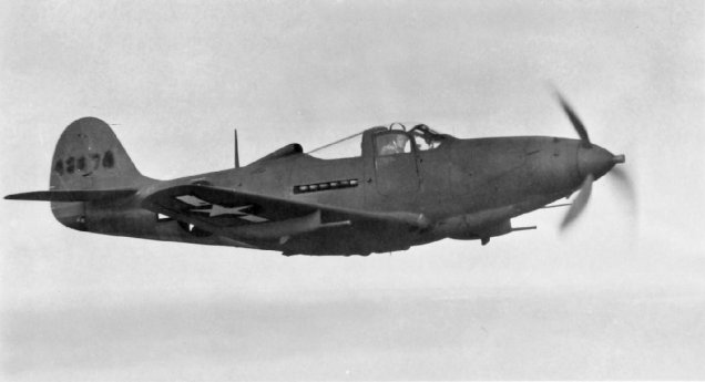
NAA P-51D Mustang: Master Lines Plan

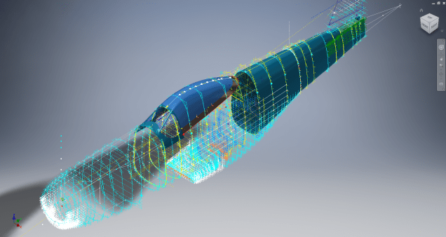
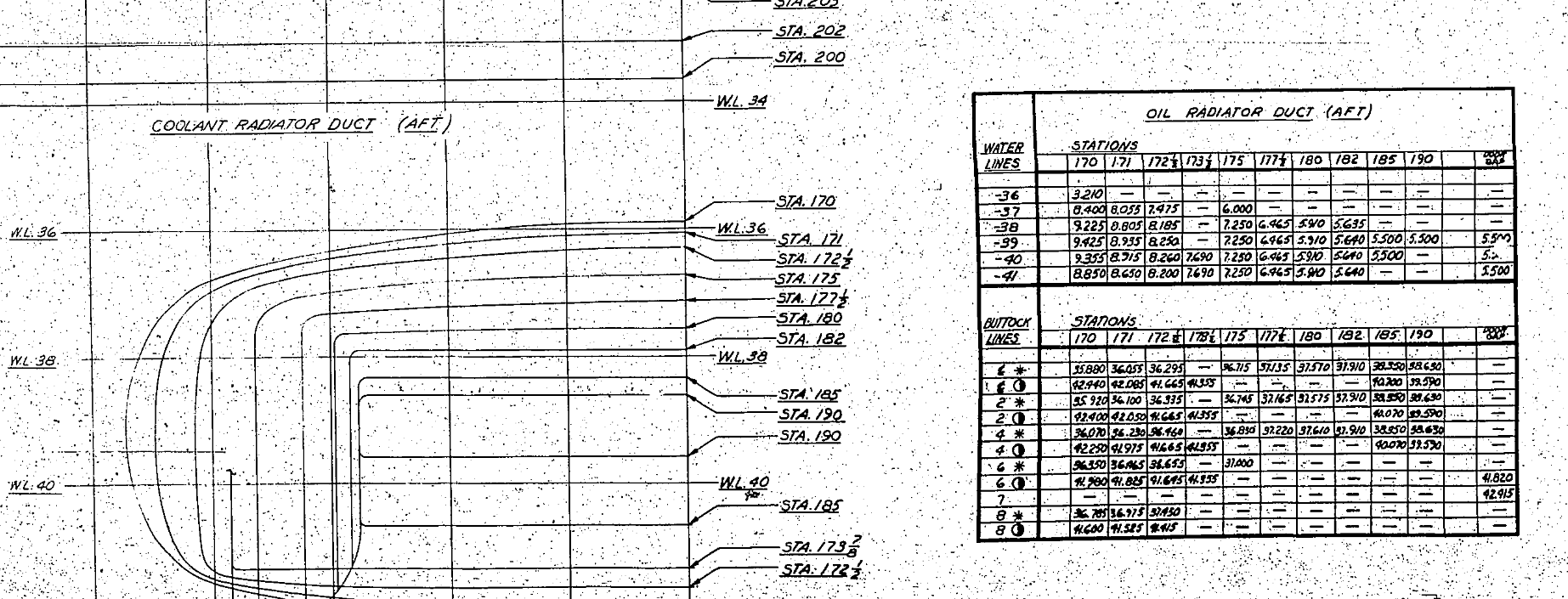
The P-51D project is progressing well with further developments on the fuselage frame profiles. I now have a comprehensive Master Lines Plan incorporating additional information obtained from mathematical analysis, drawings, reference documentation and geometric developments. I have updated and remodeled the underside Oil Cooler Air intakes, canopy, windshield, rear fuselage and fuselage tail-end. As part of the remodel the groups of ordinates for each frame for the Oil Radiator Duct, Coolant radiator Duct and Removable Scoop are now contained on their own respective work-planes. This will make it much easier to micro manage the final mold lines.

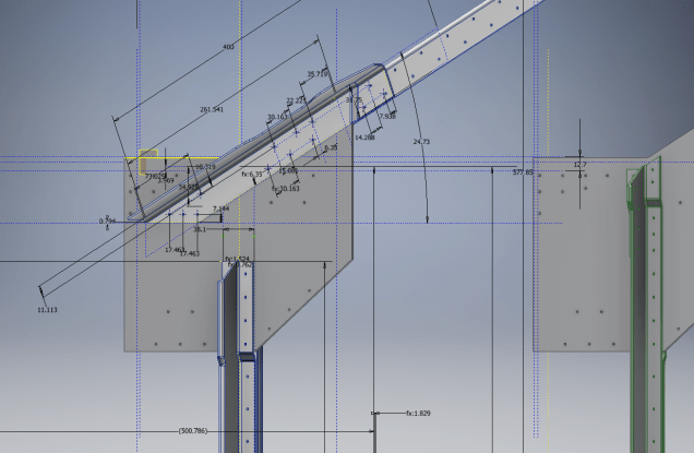
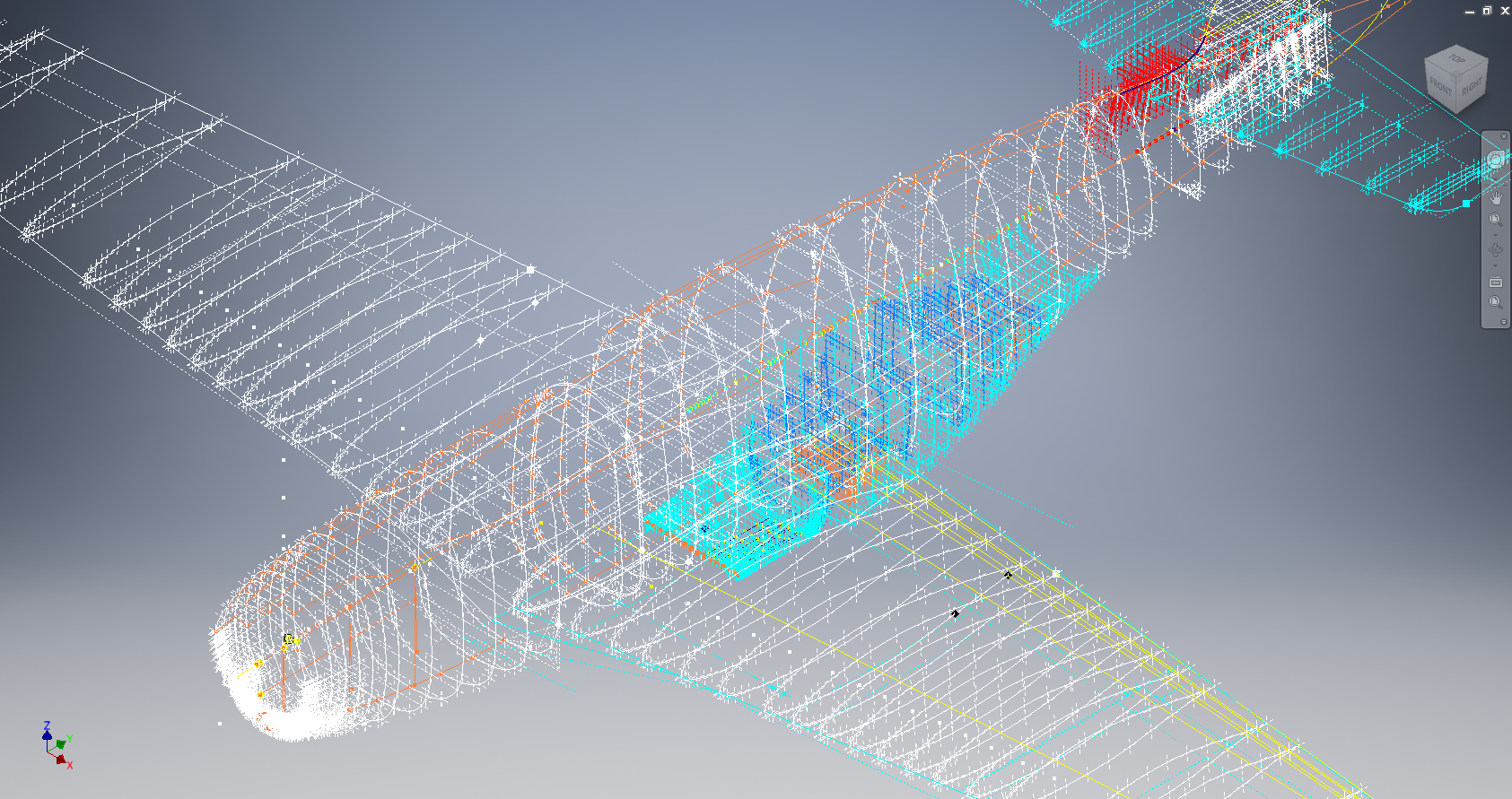
Fuselage Master Lines Plan (P-51D overlaid on P-51 B/C):

2017-07-01_14-32-09

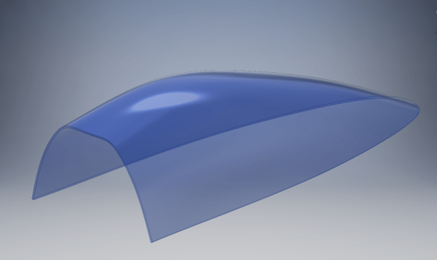
Test Lofts and developments:

2017-07-01_14-30-24

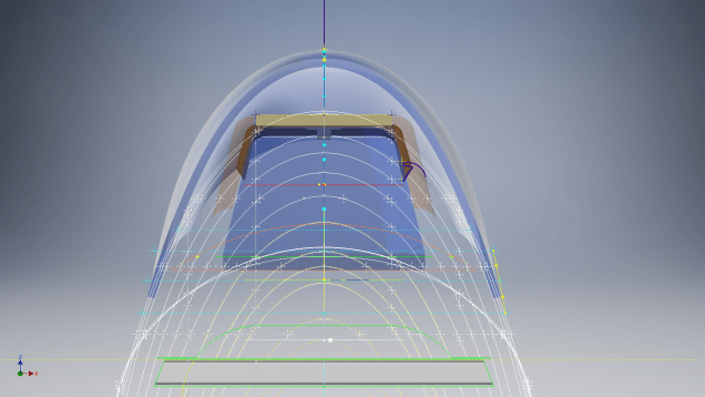
Front Views (note the Canopy Profile update from the previous article):


A month ago I was not sure how much could be achieved given the limited amount of information at hand but with due diligence and detailed research, it is quite amazing what can be accomplished.

With this template, it is now technically possible to accurately develop a CAD model for the entire fuselage structure and mechanical components for the P-51D, which would be great; but I often wonder what the value of such an undertaking would achieve, other than being a darn interesting thing to do and a test of CAD modeling skills.

Having achieved this significant milestone the time is right to conclude the work on the Mustang P-51D and P-51 B/C projects. I may continue with the P-39 project but as always I am keen to explore the options for the more obscure extinct aircraft as described in Operation Ark.

2017-07-01_00-15-20

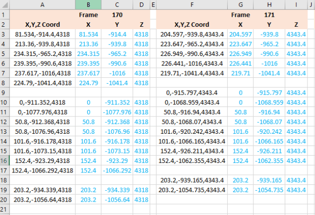
If you are planning on developing your own Master Lines plan a good place to start would be with the 1000’s of ordinates points cataloged and recorded on the spreadsheets here: Mustang P-51B/C Ordinates which also includes the wing ordinates for the P-51D and vertical stabilizer.

NAA P-51D: Canopy

NAA P-51D Mustang: Canopy

With the return to the P-51D project, I have been working on developing the fuselage and the canopy ordinates specific to the P-51D. Supporting information in this regard is hard to come by and we don’t have the luxury of tabulated ordinate values and fully detailed mold lines as we had with the P-51 B/C.

What we do have though is critical dimensions scattered amongst the 100s of drawings and documents that collectively help establish key datum points which in conjunction with conic geometric development appear to make this aspiration a feasible prospect. To give you some idea of progress this is a front view of the preliminary P-51D canopy model.

P-51D Canopy Front

I still have the windshield model to develop in order to finalise the canopy design but I am pleased with achieving this amount of progress derived from many hours of research and some straightforward geometric developments. Notice in particular the accurate tangency alignment with the known frame mold lines, it is perfectly aligned. I appreciate that there are a few variations on the profile of the canopies that were made for the P-51; some more bulbous than others, but we first need to establish a baseline which is what we will have.

As a consequence of this activity, I have also managed to develop the rear fuselage profile ordinates for the P-51D. I am rather excited by this new development in conjunction with the completed wing ordinates and the more recent vertical stabiliser it may actually be possible to have a full ordinate set uniquely for the P-51D.

Update: Below is the finished baseline canopy model profile.

2017-06-08_13-55-28

…and this is what it looks like to develop the canopy and windshield with limited known data…

P-51d Canopy Dev01

Update: August 2018 “P-51D Bubble Canopy”

The real thing…this is a model derived from a ridiculously accurate laser scan point cloud of a P-51D Bubble Canopy.

NAA P-51D Mustang: Using Ordinate Data

NAA P-51 Mustang: Using Ordinate Data Spreadsheets

A question arose during a telecon today about using the Ordinate Spreadsheets for Cad and Modelling.

2018-11-30_08-40-04

Typically for the fuselage and cowlings, the spreadsheets are set out as above. The top section replicates the layout of the original manufacturer’s drawings specifically to allow traceability for verification purposes. The section below, bordered in blue is the concatenated values from the top table in a format such that the values represent the actual X,Y,Z coordinates for each point.

2017-05-23_21-47-42
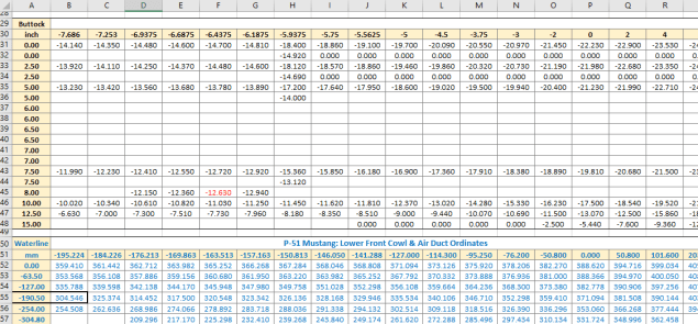
For use in Cad systems like Autocad, it is recommended to collate these in a TXT file by simply copying and pasting.

Once collated open Autocad, select the Multiple Point feature and cut and paste the entire contents of the TXT file onto the command line which in turn will import the values as points.

For other CAD systems like Inventor the preferred format is an excel spreadsheet with 3 column headers X, Y and Z.

All we have to do is to open this same TXT file from Excel as a comma delimited file, check the options presented in the opening dialogue to ensure correct formatting and save the file as an XLS. Remember to label the first row as X,Y and Z.

2017-05-23_22-06-55

When you start a sketch in Inventor there is a feature on the toolbar to import Excel data. When you import the data there are a few self-explanatory options.

2017-05-23_22-12-58

There are of course many ways of doing this and it will vary according to what CAD system you use. Importing all X, Y, Z points in a 3D sketch, for example, will align the ordinates with the current UCS, which in some cases may not be desirable. The Z value is the Frame or Station location relative to the aircraft datum, which essentially translates to being the work plane location. The X, Y values are typically the sketch coordinates normal to the work plane.

If you are working on a 2d sketch and importing the set of points as X, Y, Z values; Inventor will only import the respective X,Y values and ignore the Z value, in fact, it will notify you that it is doing this.

Update: July 2018

The ordinate spreadsheets now have an additional page that compiles the ordinates for each frame with the X,Y,Z components listed separately. This makes it easier to manage the ordinates depending on what CAD system you are importing to.

2018-07-31_23-24-09

If you require any further information then please drop me a line.

NAA P-51D Mustang: Wing Ordinate Rev

NAA P-51D & B/C Mustang: Wing Ordinate Major Update:

Thanks to Roland Hallam, I am now in receipt of new verifiable information that has prompted a return to the P51 project and a major update to the wing ordinate data sheets.

2017-05-21_15-46-57

Many of the blanks have now been filled in and new additional information added. The above image is a snapshot of the work in progress. The groups highlighted in blue are checked verified dimensions, the red values are those that have changed and those areas remaining in white have prompted an interesting conclusion. Up until now, it was presumed that the wing profiles for the P51D and P51C were the same with the exception of the wing root, however, closer inspection would now suggest that a few rib locations are also slightly different which requires further investigation.

I am still working through the new information and dissecting what is relevant to the P-51D and the P-51B/C variants. This will probably take me a while to evaluate but I am confident that this will result in the most comprehensive dataset yet compiled for the P-51 wings.

I had not expected to return to the P51 project at this time but I’m sure you will agree this is an exciting development.

Sopwith Pup:Wing Brackets

SopwithPup: Wing Brackets

This was not meant to have been a study in its own right, but out of curiosity I couldn’t help but wonder if there was enough information to actually build an accurate 3D model.

I was also curious why I had received a number of help request emails from my friend about this particular aircraft…so I decided to have a closer look. His latest query was regarding brackets similar to the one I mentioned in my previous post but specifically the centre section connecting brackets to the wings.

The left bracket belongs to the centre section and the right bracket is the connecting bracket for the wing that slots into the centre section bracket.

sp-009

The bracket dimensions are such that the centre bracket sits proud off the centre spar whilst the wing bracket is embedded in the wing spar, so technically they should just fit into one another without too much problem!! That’s the theory but the reality is it doesn’t quite align with expectations.

sp-03

This image shows the actual clear dimensions within the top and bottom rib flanges which replicate the perimeter dimensions of the wooden centre spar. In order for the centre section bracket to connect to the spar we would have to notch the top and bottom rib flanges to get it to fit. The horizontal dimension can vary (highlighted) but we will be restricted by the vertical dimension. I can’t imagine why anyone would want to notch the top and bottom flanges as this diminishes its strength. Plus there’s another issue with this…

sopwith-pup06

This preliminary model shows the problem where the centre spar is actually set back one inch to facilitate the incoming connecting bracket from the main wing. Ideally, we need to fully assemble the centre section and have it fitted to the aircraft and aligned prior to fitting the wings, but how can this be done if we can’t screw the rib flanges to the spar? I think in this instance I would shape the wooden spars in such a manner as to facilitate fitting of the flanges and mating with the wing spars.

I have done some research on this and it appears to be a known issue with some clever blokes just redesigning the connectors to make it work better or tapering the wing spar to good effect as shown below.

sdasmpup

It looks as though the wing spar is tapered with a smaller bracket sized to fit within the centre bracket. That would work and likely an improvement implemented in the workshop. A very rough preliminary study could look something like this…

…it does need a lot more work but I don’t have a lot of time to develop it further right now!

The design in many respects seems a little rough and ready, but we have to remember in those days they were under a huge amount of pressure to get these aircraft built and get them into the field. The life expectancy of these aircraft was only six weeks so replacements had to be shipped out in rather a quick time.

No disrespect either to Tom Sopwith and his engineers, these things actually flew rather well regardless of the vagaries of the design and what may seem to be annoyances to us may well be things they would naturally deal with in the workshop without any hassle.

It is very tempting to continue developing the Sopwith Pup but to do so efficiently would require setting out the basic geometry for the entire aircraft, identifying the anomalies and determining suitable resolutions as close as possible to the original design intent. I’m not sure I have the time nor the inclination to do so.

This has been a welcome distraction from the P-39 Airacobra project and will likely feature in a few more posts as I will surely continue to receive help requests from my good friend.

Sopwith Pup: Technote

Sopwith Pup: Spar Clip Technote

The Sopwith Pup is a single seater biplane built by the Sopwith Aviation Company, another aircraft in my archive, though not one that I have done much work on. This is just a quick technote; so not a new project; my priority still lies with the P-39 Airacobra.

I received an email from a close friend and he asked if I could help him out with this model for the main spar clip, item number 1393-1 from the Sopwith drawings. The area in question was the cable lug at the base of this clip, which comprises 2 parts.

The problem related to matching the profile of the top part to the profile of the lower part, without extensive or complex modelling. For the lower part, I decided to use the sheet metal features to create this as a multi-body part which I would then use as a template to profile the upper section that is essentially an extension of the main model.

What he was trying to do was project a sketch from the each face of the lower part, extrude each sketch and then fit a bend to connect the two extrusions. He reckoned this was more complicated than it should be and asked me if there was better way of doing this.

He was actually not that far from achieving a simpler solution, he just needed to adapt the process a little bit.

sc-03

In a previous article for the P-39 cabin glass I discussed the merits of selecting the solid surfaces as a means to modelling the jogged edges. I have used a similar technique here for developing the upper part of the lug.

Simply by selecting the top surfaces of the lower part as shown above; we then apply a thickness to this selection and opt to merge with the upper part as shown. There we have it; an exact match and fit between lower and upper lug parts in one step!.

It looks simple and often the best solution is, but occasionally it is easy to overlook the fact that we can manipulate the surfaces of a single solid model to create new separate parts without too much effort.

sp-05

Squaring the Edge:

The Sopwith drawings for this part and many other similar parts are a little misleading given that they show the edges of these components as beveled. This is normally not good practice, particularly when metal meets timber. Ideally we need to square the edges to negate this problem and to facilitate the cutting of the developed sheet metal pattern.

sc-06

These brackets are an awkward shape which requires some careful planning to ensure that the model is correct and can be manufactured. So to achieve this I occasionally use surfaces to set-out the basic cut profile shape and then thicken.

Thickening a surface model is actually a good way of working due to the thickness being applied normal (perpendicular) to the surfaces, thus by definition achieving a good square edge to the developed pattern.

As you can see in the image on the right the edges are square and easy to cut.

The other way of doing this is using the cut option feature from the sheet metal command.

sc-10

By selecting the “Cut Normal” option in the dialogue this will ensure that each of the edges from this extrusion will be square to the surface when flattened.

Whilst we are on this subject; the weld seam at the top of this bracket is something I would consider improving by having a thin continuous metal strip either side of the seam instead of 3 smaller widths (top image) which may distort the metal, something like this (A):

sc-11

Notice I have tidied up the bend at (B)…this gives a much cleaner profile when the draft angle is quite small. I should note that I don’t normally take liberties wth the manufacturer’s details, but occasionally exploring options to see how things could be improved can be quite an interesting exercise.

I should note that it is normally good practice to state on the 2D manufacturing drawing a “Break Edge” minimum size anyway for all edges even when square cut.

Bell P-39 Airacobra: Fuselage

Bell P-39 Airacobra: Fuselage

This is an update on the P-39 project. I have actually been drifting between this and the P-51 Mustang as a number of inquiries have come in regarding the ordinates and various questions on the Oil Cooler model and landing gear mechanisms; which has been an interesting diversion.

Getting back on topic, I thought it may be prudent to write a quick update on what I am doing with the P-39 Airacobra and where I hope the journey will take me.

I have of course continued working on the ordinate data spreadsheet which is derived from the part drawings themselves. This serves as a check whilst I am developing the structure. The 3D models are being developed in context, i.e the individual part models are located to the 3D spatial ordinates relative to a single datum so when I plug these into the assembly they will import to the correct 3D location thus negating the requirement for constraints.

2016-08-12_22-48-54

This is the first time I have worked this way as I usually just model the part and then constrain to the corresponding items in the assembly, but this is usually dependent on the quality of the assembly scans to clearly identify and ensure correct alignment of the parts. As we all probably know these scanned files are the most likely to have problems with legibility. In many respects having the part files modelled relative to ordinates in 3D space ensures that the parts line up correctly and I don’t have to worry too much about the quality of the assembly scans.

P-39 Airacobra Fuselage

The P-39 main assembly drawings are actually not too bad as the image above shows. This is a scrap view of the fuselage Longitudinal, comprising many small parts all riveted together to form the assembly. The area in red is where I am working at the moment; which is a major node; just aft of the engine bay; where the many struts and braces overlap on both sides of the stiffener plate. The following image gives you some idea of the detail to which this is being developed.

P-39 Airacobra Fuselage1

The pilot holes for the rivets are unique to each individual part and just like the real process of construction these holes will be match drilled to all the other corresponding parts in assembly.

Modelling the complex parts and locating all those holes takes a lot of time but I believe the end result will be worthwhile. With this degree of accuracy you could just about build one of these aircraft from scratch!.

Quick Technote: P-39-01
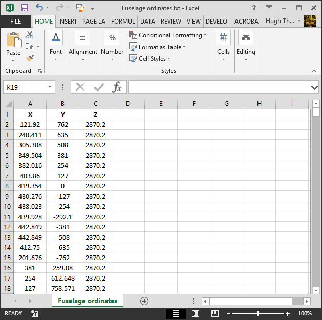
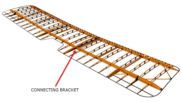
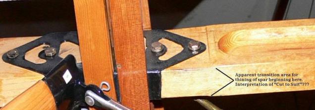
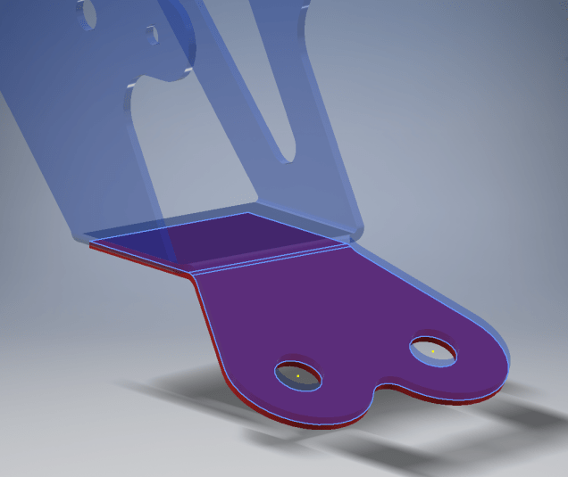
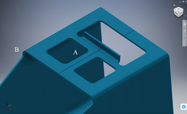
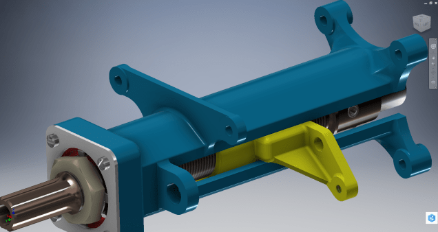
This is the lower level fuselage cross member that has a built in twist to align with the connecting frames at both ends. The model consists of 3 profiles with the 2 outer ones containing a small angular deviation in the centre at point A. Normally I would loft the profiles to create the finished surface but this projects the deviation throughout the length giving us 2 surfaces; which does not look good.

I therefore deleted the resulting 2 base surfaces and simply replaced them with a boundary surface. I’m sure you will agree the result is a much smoother gradation of curvature; that matches expectations.


Bell P-39 Airacobra: New Project

Bell P-39 Airacobra: New Project

Bell_P-39Q

I recently received a set of the P-39 scanned blueprints for the Bell P-39 Airacobra. An underrated aircraft not popular with the Americans or Brits but was very successful with the Russian air force on the Eastern Front, particularly the 9 GIAP, known as the ‘Regiment of Aces’. There are plenty online resources documenting the amazing history of this aircraft, suffice that I would find it difficult to add anything significantly new here.

The set of drawings; approx 11,000; are actually very good quality scans of which I have spent some time looking through and randomly modeled a few items…like this part for the Landing gear nose wheel travel indicator.

p-39 airacobra

Most aspects of the main structure are also well covered with the ordinates included on the detail drawings and not as a separate sheet. This could be an interesting project and although not entirely a rare aircraft; as we still have a few flying examples and static displays; I do think it will be a worthwhile aircraft to develop. Most of the examples unfortunately are based in the US but there is one on display in Finland, for which a visit is on my to-do-list later this year.

I’ve played about with modelling some bits and reviewed the drawing organisation. I now need to get down to some serious work starting with reverse engineering the ordinate data on the drawings to establish an ordinate record and create the mold lines.

Sample: Ordinate data copied from manufacturer drawings maintaining original format.

P-39 Ordinates

2016-07-17_04-10-39

This Dataset is then restructured in a separate worksheet to derive the X,Y,Z coordinates for input into CAD.

The ordinates are important for modelling so we can loft the surfaces to check the angle of the frame flanges for correct alignment and also enables us to model parts in the 3d space sufficient that their location in the final assembly is already determined.

2016-08-17_04-39-38

This is definitely a long-term project for which I will post updates on progress, though not quite as regular as I have done in the past for previous projects.

Other project Ordinates:

P-51 Mustang available here: Mustang P-51 B/C Ordinates

Ta-152 available here: FW 190 & Ta152: Ordinates

Mustang P-51 B/C Ordinates

Mustang P-51 B/C and P-51 D Ordinates:

P-51BC Layout

I have had a number of requests for the ordinate spreadsheets I developed for the Mustang P-51 B/C and D fuselage, cowl, cooler and air intakes, so I have decided to make them available to all; which could save you considerable time and effort.

The ordinates are listed on 10 separate Excel workbooks with 18 spreadsheets for all known ordinates from manufacturers data. The ordinate listings are in both mm and inches with the X,Y,Z coordinates extrapolated from this data-set for ease of transferring to a suitable CAD system. The total points listed are literally thousands.

P-51 D Layout102-00005: Fuselage (BC main)
102-00006: Fuselage (forward to cowl)
102-00007: Removable Scoop (fuselage, Int and Ext)
102-00008: Coolant Radiator Duct (Aft Section)
102-00008: Coolant Radiator Duct (Fwd Section)
102-00008: Oil Radiator Duct (Aft)
102-00009: Carb Air Scoop (Cowl)
106-00006: Wing (P-51D)
73-00006: Wing (P-51BC)
 
+ Autocad DWG Fuselage Frame & Wing Profiles P-51 B/C and P-51D (ref only)
NAA Master Dimensions Report (wings, fuselage, landing gear).
Include scans of original source documents for reference.
 
The spreadsheets are not locked or protected so you can manipulate the core data to suit your own applications.
The P-51D fuselage profiles are reference only due to being mathematically generated based on original NAA methods and thus are not verified.

This represents a huge number of hours worked, meticulously listing each ordinate individually and then creating cad drawings to check the ordinates and derive the ordinates that are unclear on the manufacturers’ drawings.

2016-06-04_23-33-26

The ordinates for the P-51D wings comprises 2 sheets; the first listing the tabulated data as per the original manufacturer drawing and the second extrapolated to compile the X,Y,Z coordinates for input into CAD.

P-51D WING ORDINATE

P-51 Wing Profiles

Update 20 Aug 2019:

The spreadsheets now include the OLEO undercarriage and general tidy up of datasheets for consistency. Now probably the most comprehensive and complete dimensional study of the P-51 B/C and D. 2018-09-20_22-45-40

Horizontal Stabiliser and Fillet Ordinates layout:

Mustang P-51 BC

Sample data for P–51B/C and P-51D;

For further details see this more descriptive post or send me an email to HughTechnotes@gmail.com 

2D Draughting to 3D Models

2D Draughting to 3D Conversion

2d to 3dTechnical drawings, detailing the specifics of your design can be critical for the communication both internally and externally. We can transform your 2D CAD or fully dimensioned legacy paper drawings to 3D Models using our experienced engineers to ensure drawings are 100% accurate and adhere to the most relevant standards and protocols.

3D Cad models will be fully inclusive of manufacturing tolerances as specified. New 2D drawings will be derived from the 3D model, dimensioned and denoted as original.

Attributes and BIM IFC data can be incorporated according to your engineering and company standards for Structural, Mechanical, Building Services and Equipment projects.

We normally use the Autodesk Inventor but are equally capable with all the Autocad based products from which we can provide native format model files or various other formats to suit your requirements, including DWG, IFC, STEP and STL.

We can provide CAD modelling services for your restoration project, adhering to all appropriate standards and design specifications.exit