Bell P-39 Airacobra: New Project

Bell P-39 Airacobra: New Project

Bell_P-39Q

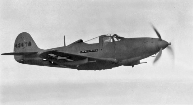
I recently received a set of the P-39 scanned blueprints for the Bell P-39 Airacobra. An underrated aircraft not popular with the Americans or Brits but was very successful with the Russian air force on the Eastern Front, particularly the 9 GIAP, known as the ‘Regiment of Aces’. There are plenty online resources documenting the amazing history of this aircraft, suffice that I would find it difficult to add anything significantly new here.

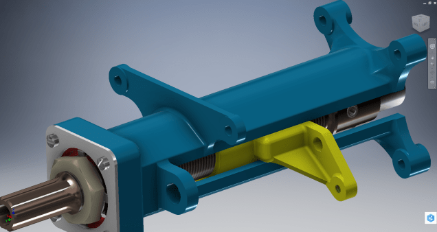
The set of drawings; approx 11,000; are actually very good quality scans of which I have spent some time looking through and randomly modeled a few items…like this part for the Landing gear nose wheel travel indicator.

p-39 airacobra

Most aspects of the main structure are also well covered with the ordinates included on the detail drawings and not as a separate sheet. This could be an interesting project and although not entirely a rare aircraft; as we still have a few flying examples and static displays; I do think it will be a worthwhile aircraft to develop. Most of the examples unfortunately are based in the US but there is one on display in Finland, for which a visit is on my to-do-list later this year.

I’ve played about with modelling some bits and reviewed the drawing organisation. I now need to get down to some serious work starting with reverse engineering the ordinate data on the drawings to establish an ordinate record and create the mold lines.

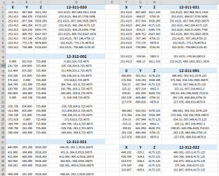
Sample: Ordinate data copied from manufacturer drawings maintaining original format.

P-39 Ordinates

2016-07-17_04-10-39

This Dataset is then restructured in a separate worksheet to derive the X,Y,Z coordinates for input into CAD.

The ordinates are important for modelling so we can loft the surfaces to check the angle of the frame flanges for correct alignment and also enables us to model parts in the 3d space sufficient that their location in the final assembly is already determined.

2016-08-17_04-39-38

This is definitely a long-term project for which I will post updates on progress, though not quite as regular as I have done in the past for previous projects.

Other project Ordinates:

P-51 Mustang available here: Mustang P-51 B/C Ordinates

Ta-152 available here: FW 190 & Ta152: Ordinates

Mustang P-51 B/C Ordinates

Mustang P-51 B/C and P-51 D Ordinates:

P-51BC Layout

I have had a number of requests for the ordinate spreadsheets I developed for the Mustang P-51 B/C and D fuselage, cowl, cooler and air intakes, so I have decided to make them available to all; which could save you considerable time and effort.

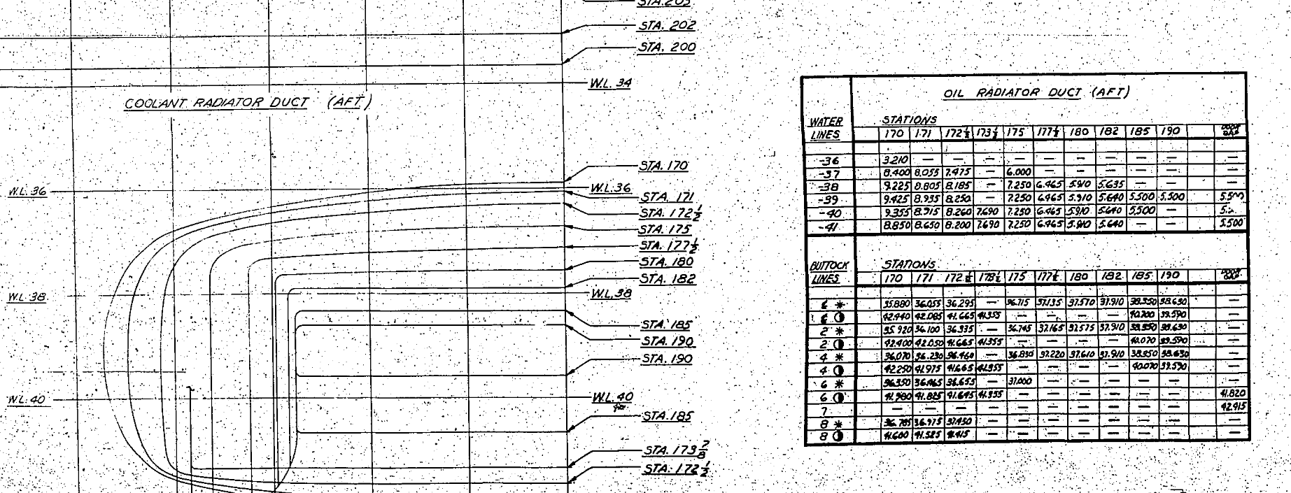
The ordinates are listed on 10 separate Excel workbooks with 18 spreadsheets for all known ordinates from manufacturers data. The ordinate listings are in both mm and inches with the X,Y,Z coordinates extrapolated from this data-set for ease of transferring to a suitable CAD system. The total points listed are literally thousands.

P-51 D Layout102-00005: Fuselage (BC main)
102-00006: Fuselage (forward to cowl)
102-00007: Removable Scoop (fuselage, Int and Ext)
102-00008: Coolant Radiator Duct (Aft Section)
102-00008: Coolant Radiator Duct (Fwd Section)
102-00008: Oil Radiator Duct (Aft)
102-00009: Carb Air Scoop (Cowl)
106-00006: Wing (P-51D)
73-00006: Wing (P-51BC)
 
+ Autocad DWG Fuselage Frame & Wing Profiles P-51 B/C and P-51D (ref only)
NAA Master Dimensions Report (wings, fuselage, landing gear).
Include scans of original source documents for reference.
 
The spreadsheets are not locked or protected so you can manipulate the core data to suit your own applications.
The P-51D fuselage profiles are reference only due to being mathematically generated based on original NAA methods and thus are not verified.

This represents a huge number of hours worked, meticulously listing each ordinate individually and then creating cad drawings to check the ordinates and derive the ordinates that are unclear on the manufacturers’ drawings.

2016-06-04_23-33-26

The ordinates for the P-51D wings comprises 2 sheets; the first listing the tabulated data as per the original manufacturer drawing and the second extrapolated to compile the X,Y,Z coordinates for input into CAD.

P-51D WING ORDINATE

P-51 Wing Profiles

Update 20 Aug 2019:

The spreadsheets now include the OLEO undercarriage and general tidy up of datasheets for consistency. Now probably the most comprehensive and complete dimensional study of the P-51 B/C and D. 2018-09-20_22-45-40

Horizontal Stabiliser and Fillet Ordinates layout:

Mustang P-51 BC

Sample data for P–51B/C and P-51D;

For further details see this more descriptive post or send me an email to HughTechnotes@gmail.com 

2D Draughting to 3D Models

2D Draughting to 3D Conversion

2d to 3dTechnical drawings, detailing the specifics of your design can be critical for the communication both internally and externally. We can transform your 2D CAD or fully dimensioned legacy paper drawings to 3D Models using our experienced engineers to ensure drawings are 100% accurate and adhere to the most relevant standards and protocols.

3D Cad models will be fully inclusive of manufacturing tolerances as specified. New 2D drawings will be derived from the 3D model, dimensioned and denoted as original.

Attributes and BIM IFC data can be incorporated according to your engineering and company standards for Structural, Mechanical, Building Services and Equipment projects.

We normally use the Autodesk Inventor but are equally capable with all the Autocad based products from which we can provide native format model files or various other formats to suit your requirements, including DWG, IFC, STEP and STL.

We can provide CAD modelling services for your restoration project, adhering to all appropriate standards and design specifications.exit

The Journey

The Journey:

This blog has been about the journey cataloging my passion for historical aviation design and construction. Its about the geometry; the ordinates and plans, about the designs and construction; from wood and canvass to full metal and alloy and the inspirations for the designs. The sheet metal work, the manufacturing, the mechanics, materials, electrics and hydraulics.

Its been an interesting time studying the different aircraft construction techniques and design methods. The different approaches to how different designers organise and develop the designs on the drawing board, sometimes accumulating 100o’s of drawings for a single aircraft…an admin challenge that even today would be quite daunting.

Not all my work has been published here, only a few examples that I think may be of particular interest. The evolution of the FW-190 to Ta-152, the various marks of the Spitfire, the early design characteristics for the Tiger Moth, the Mustang P-51 conic research and mathematical analysis culminating in a broad spectrum of research material that lays the foundation for the next chapter in my work.

I have learned a lot from this work which has been both challenging and frustrating. Its tested the limitations of my knowledge and the CAD systems we have come to rely on so much in our designs today.

Not many of the archive drawings sets I have are representative of a complete aircraft, often missing key information or simply illegible; though the latter sometimes can be overcome by studying other aspects of the design. I am often asked if I would consider creating an entire aircraft design in CAD that could actually be manufactured and whilst the answer is of course yes I would be reluctant to spend the considerable time required for any aircraft for which we have many flying examples.

Having said that Operation Ark was setup to undertake such a task for an extinct or rare aircraft depending on availability of sufficient design data. This work is still in progress and will take a while to resource, evaluate and fund such a project.

In the interim I have received a new set of archive material for an aircraft that was used extensively by Russia on the Eastern front which will be featured here in a few months time.

For now there wont be many updates but please do drop me a line as its always good to hear from the many readers of this blog about their own experiences in the exciting world of historical aviation.

NAA P-51D Mustang: Carb Air Scoop

NAA P-51D Mustang: Carb Air Scoop

In an earlier post I discussed in some detail the progression of model development for the Carburetor Air Scoop (Lower Cowling) inlet and I mentioned that the final Air Scoop would be uploaded upon completion. Earlier Post : Air Scoop Prelim work:

It has actually been completed for awhile; I just forgot to upload it!

So here it is and if anyone has attempted to model a complex surface of this type you will understand how difficult this can be. Needless to say the Freeform T-Splines were invaluable in obtaining the correct surface.

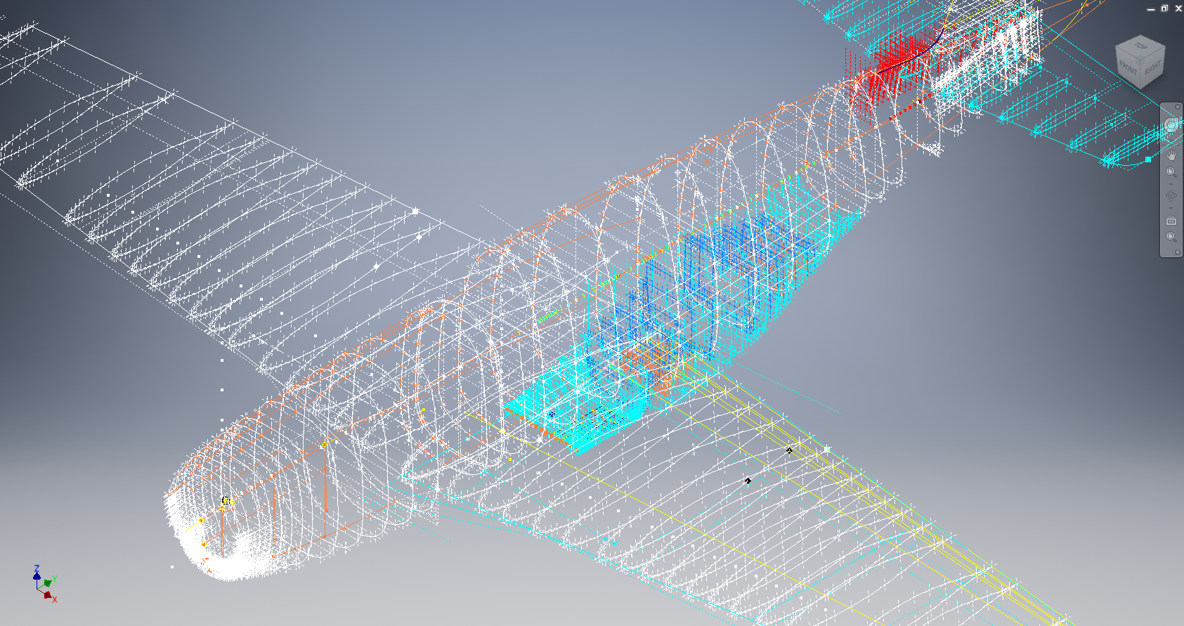
The surface model is attached to over 300 ordinate points with numerous contour and fairing curves generated in preparation for the final surface modelling.

The data was first prepared in a spreadsheet; listing all ordinate points in mm and inch dimensions from which I extrapolated the 3D coordinates for each point; essentially creating a point cloud.

The ordinates were imported into Autocad, analysed and then the points grouped accordingly to define the contours and fairing lines.

This was then imported into Inventor and the surface painstakingly built up in each separate square grid attaching all the ordinate points. There was no easy way of doing this; I know I tried!

I am delighted to have finally completed this particular model having consumed many hours trying various methods to get it just right.

Republic XP-47J Superbolt

In my endeavours to research the forgotten aircraft of the war eras and the remarkable people that designed, built and flew them I came across this article on the Republic XP-47J Superbolt.
What is important; apart from the fact that this aircraft recorded the highest speed in level flight for a propeller-driven aircraft in 1944; is the tribute noted in the response column by the daughter of the pilot; Mike Ritchie who made that historical flight.
Perhaps the XP-47J should be added to the list for the Operation Ark project.

William Pearce's avatarOld Machine Press

By William Pearce

In mid-1942, Republic Aviation Corporation initiated a design study to lighten their P-47 Thunderbolt fighter for improved performance. The Thunderbolt had been steadily gaining weight as the design matured, while comparative enemy aircraft, like the Focke-Wulf FW 190A, were much lighter. Republic officially proposed a light-P-47 to the Army Air Force (AAF) on 22 November 1942. On 1 April 1943, the AAF gave Republic a letter of intent to purchase two light-weight P-47s, and the contract was officially approved on 18 June 1943. This new aircraft was designated the XP-47J.

Republic XP-47J front An early image of the Republic XP-47J before the Superman nose art was applied. Note the cooling fan vanes around the spinner inside the cowling.

As with all P-47s, Alexander Kartveli was the main designer of the XP-47J, and he was assisted by Murray Burkow. The XP-47J was similar in appearance to a P-47B, but it was…

View original post 1,100 more words

NAA P-51D Mustang: Fuselage: Conics

NAA P-51D Mustang: Fuselage: Conics

In the preceding article I had some fun with polynomials and how they could be useful for determining a smooth fit spline for the development of the Mustang fuselage. As a follow up to that article I wanted to share some research relating to conics.

The Mustang P-51 was the first aircraft to be completely defined by conics. The designer Edgar Schmued worked with Roy Liming to mathematically analyze the Mustangs shapes, tangents and curves. Conics were used by NAA as far back as 1932 though many of the techniques and equations we use today however were not actually in use until 1959.

The Bézier curves for example were based on the Bernstein polynomial which had been known since 1912 but its application for graphics was not understood till much later. Bézier curves were widely publicized in 1962 by the French engineer Pierre Bézier, who used them to design automobile bodies at Renault. The study of these curves was however first developed in 1959 by mathematician Paul de Casteljau using de Casteljau’s algorithm, a numerically stable method to evaluate Bézier curves at Citroën.

So I started to wonder how did Edgar Schmued and Roy Liming actually apply conic principles and what methods did they use for the Mustang design!

The documentation I have available for the Mustang Wind Tunnel models gives us a clue at the geometric construction for the fuselage frames. The designers used smooth conic sections with key parameters controlled by longitudinal shoulder and slope control curves. The longitudinal curves defined fullness and tangency values for the conics from forward to aft of the fuselage. The P-51 designers found that this technique allowed them to accurately control sectional areas to secure the required effects for lift, drag, stability, and overall performance.

2015-08-03_22-50-45

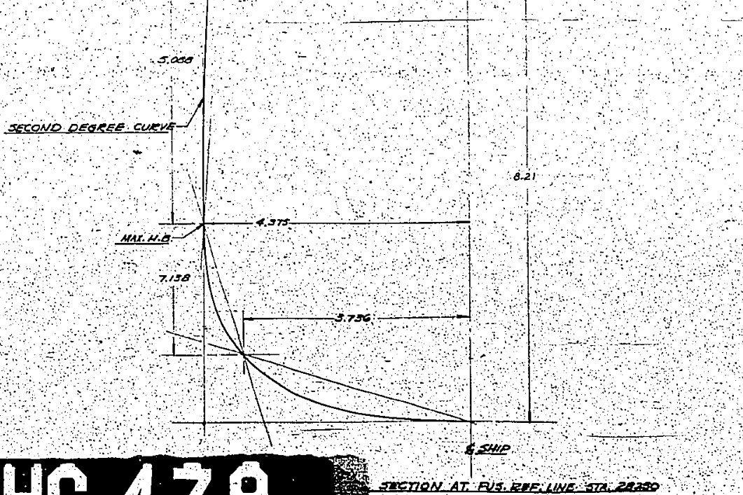
Here we see a scrap view from the wind tunnel models, showing clearly the development of the conic constrained by 2 tangent lines and a third Shoulder Point as a known point on the designed curve.

The intersections of lines extended from the Max Half breadth point and the Lower Ship Centre point illustrate a drafting technique for creating the finished curve for the lower section of a fuselage frame.

Hugh P-51 ConicsTaking this method further we can describe a curve using a series of extended lines to define any point on the curve as shown in my Cad drawing.

This is my interpretation of a technique for the drafting of a typical Mustang fuselage frame. I haven’t seen this technique applied to a full fuselage profile and whilst the design information I have suggests a similar approach by the Mustang designers I can’t verify that this was the actual technique used.

It is not possible within the scope of this article to go into the detail of this technique, but suffice to say that selecting only 3 points for the lower and upper sections contained within tangential lines provides the basis for accurately determining any other ordinate point on the particular curve. I have uploaded a short video on Youtube here: Drawing a Conic

This is actually a lot better than using the polynomial equations for frame geometry as they only give you a best fit approach based on the tabled ordinates; with limitations; whilst this construction technique will allow the flexibility of defining any point on the curve to an unprecedented degree of accuracy when created in CAD…it works!

So what else did these visionary guys do? I am really keen to further research the mathematical approach that Edgar Schmued and Roy Liming used in the other aspects of the aircraft design and uncover the methods that made the Mustang unique.

It is my hope that by sharing my research and developments that this will inspire others to also research the work of the designers from this era and hopefully in some small measure encourage support for our project “Operation Ark”.

2015-08-06_03-06-27Update: I must have spent a full day browsing through the archives to find more information that would assist with understanding the conics development and thankfully I came across this NAA lines drawing for the cowl on P-51C (NA-103).

This shows the development and tangent lines for everything including the shoulder lines and the fairing lines as well as the main profile contour lines.

Its very important to spend time verifying the information used for developing these designs to validate the research. Sometimes I could spend days just looking for small scraps of information just to verify one dimension, which happened quite a lot on the Ta-152 project!

Full profiles drawn in Autocad from comprehensive excel spreadsheet ordinate collections now available for download. See this article for details.

NAA P-51D Mustang: Fuselage Lines; Polynomials

NAA P-51D Mustang: Fuselage Lines; Polynomials.

This evening I spent some time looking back through some old notes I had on fuselage design, particularly Conic sections and Setting-out design theory.

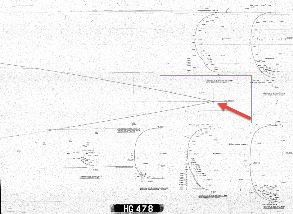
Checking through the archives for the Mustang P-51 we have a design set for the wind tunnel model with a line plan showing the Shoulder Points (SP) and the “point of convergence” where the upper line of the Mustang fuselage converges with the lower fuselage line and the Fuselage reference line.

2015-07-31_03-40-50The Wind Tunnel drawings are a quarter scale but are quite accurate.

Here we can see the “point of convergence” actually defined on the the wind tunnel drawing at the scaled sta 92. Technically station 92 does not exist as it is outwith the fabric of the WT aircraft, but for convenience I have defined it!

So with this in mind I decided to undertake an experiment to calculate the “point of convergence” with the fuselage ref line according to the manufactured ordinates.
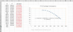
2015-07-31_12-43-55For this exercise I used the upper line of the fuselage, shown here as X,Y values starting from Station 113 and created a line chart.

I applied an third order polynomial equation to the line chart with a scientific value to 5 decimal places to increase the accuracy.

I recalculated the values of the Y ordinate to check that the formula produced an accurate result; shown in red. As you can see the resulting values are very close to the original Y values.

The last X value is the projected value I want to calculate to achieve a “close to zero” Y coordinate thus by definition being the calculated “point of convergence”. This value is 9518mm (374.725 inches) which compares quite well with the Wind Tunnel drawings showing this to be 92*4=368 inches.

Should I recreate this exercise but instead use a fifth or sixth order polynomial equation I am quite sure the resulting value for the point of convergence would be closer yet to the scaled up wind tunnel value.

Normally for this type of exercise I would work with tangent lines and the start points of the upper and lower fuselage lines from predefined Shoulder Points.

This was a bit of fun just to demonstrate how we can use the power of spreadsheets and mathematical equations to assist with developing our Cad designs.

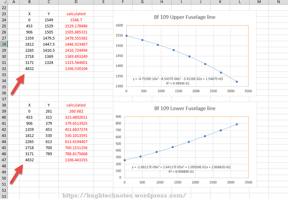
Bf 109Update: I decided to play about with this a bit more and had a look at the fuselage lines for the Bf109. I don’t have the design “point of convergence” for comparison but decided to do it anyway to find the convergence between the Lower and Upper fuselage lines.

These points are measured from a ground datum at 800mm below the fuselage reference line.

The stations/frames are from 2 – 8 inclusive. As you can see the calculated values verify the existing ordinate dimensions with the projected “point of convergence” calculated at 4832mm from station/frame 2.

These are the fuselage lines on the vertical plane which in theory should share the same convergence point for the fuselage lines on the horizontal plane (technically plan of max width)…an exercise for some other time!

What is even more interesting is that a line equation can be used to generate a spline in both the Inventor & Solidworks cad products… as a check to verify the cad work this is enormously useful!
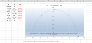
2015-08-01_00-02-16Another example of application would be for the frames or station profiles.

In this example I have applied a polynomial equation to a set of ordinates for the top section of station 300 for the P-51 Mustang.

This needs a full profile as an arc to achieve an accurate result, which I’ve applied as a sixth order polynomial…you cant get much more accurate than this with Excel!

Ideally we would wish to extend this arc to the max width ordinate, which would add another negative ordinate (below the base line) to the graph…for some unknown reason Excel finds it difficult to compute an acceptable polynomial with 2 sets of negative values, so I would have to transpose the ordinates accordingly.

The Mustang ordinates induce a minuscule negative curvature on the top rear fuselage frames when you create a CAD profile just using the ordinate values from the NAA drawings. Its not detrimental in anyway but it is rather annoying…so to obviate these issues I could utilize a polynomial solution to adjust the ordinates to get a positive curvature. The adjustment is micro millimeters, but hey that’s the way that CAD works.


Mustang P-51CAnother Update:
Out of curiosity I recalculated; to a higher degree of accuracy; the upper fuselage line for the P-51 and contrasted that with a similar calculation for the lower line of the fuselage.

The calculated point of convergence of both lines based on a 4th order polynomial to 5 decimal places is at 9375mm and slightly above the fuselage reference line at +18mm. Factoring in error based on the original ordinates being accurate to 1/16th inch and possible error as a consequence of a higher order polynomial I think this is a reasonable result. Its interesting to note the variation with the results we got before.

This is certainly closer to the expected values based on the wind tunnel data. The squiggly line by the way on the lower part of the fuselage is the plotted max half breadths; which is rather interesting!

Confirmation; have received confirmation that the intended point of convergence for the upper and lower fuselage lines is at Sta 368, which is at 9347.2mm…this is great!!

All CAD profiles included in the P-51 Mustang Ordinate Package now available. Refer promotion here.
NAA P-51D Mustang: Standard Part Models & Specs

NAA P-51D Mustang: Standard Part Models & Specs.

I have revisited the standard parts I have been producing for this project to verify that the information is correct and in compliance with the latest National Standards and specifications.

As mentioned previously I will be developing the parts for Bolts, Nuts, Washers, Pulleys Turnbuckles etc…in fact everything that constitutes a standard component pertinent to aircraft manufacture.

The parts specified for the P-51 are universal which have been updated over the years and superseded with new part numbers. These parts are suitable for reuse on other projects, in particular the forthcoming Operation Ark project.

To raise funds to support the “Operation Ark” project I have decided to make these 3D Cad parts library available for a small cost.

2015-07-26_15-26-24  2015-07-26_15-26-52

The part above is the Clevis End (Part #AN161), dimensioned in accordance with the MS21252P 2007 specification. All sizes are incorporated within an Inventor iPart model and in a separate spreadsheet.

“As from 2007 the parts covered by dash numbers shown on AN161 are canceled after 10 December 1971. Steel, carbon and alloy MS21252 parts are inactive for new design. Use only 17-4 PH stainless steel parts for new design and replacement for comparable alloy and carbon steel MS21252 parts and AN161 parts. The canceled AN161 parts and alloy and carbon steel MS21252 parts cannot replace comparable 17-4 PH stainless parts and should be used until existing stock is depleted.”

The CAD 3D model parts include both the AN161 parts number and the MS21252 Part number for comparison. The 17-4 PH number is not included in the model but is listed on the accompanying spreadsheet.

2015-07-27_20-05-59Currently only a few parts are verified; please refer to the Resources page for updates as additional libraries are made available or if you have a special request for a library to be created then drop me a line.

For further details send an email to hughtechnotes@gmail.com

NAA P-51D Mustang: Project Cad Technote; Smart Parts Vb

NAA P-51D Mustang: Project Cad Technote; Smart Parts Vb

I was looking at options for routing the cables in the tailwheel assembly. There is potential for a lot of ancillary routing for pipes and cables yet to be done in this assembly so I have deliberately shied away from the adaptive parts (which I am not keen on) and the typical pipe and cable routing functions.

Also the cables are comprised of end terminals and many are sleeved for part of their length, which would mean having to route several times if I was to do this using the routing functions.

What I really wanted to do is have a sub assembly that contains the cable with all its bits in one sub assembly file but using the coordinates from the assembly to ensure correctness.

Extracting point coordinates from an Inventor assembly is not that straightforward requiring as in this case a vb solution, but first I had to define the key points.

2015-07-23_02-51-10      2015-07-23_02-44-30      2015-07-23_02-46-01

I use the term “smart parts” and what this entails is for the parts or sub assemblies to contain additional geometry that will assist with other modelling activities like cable routing.

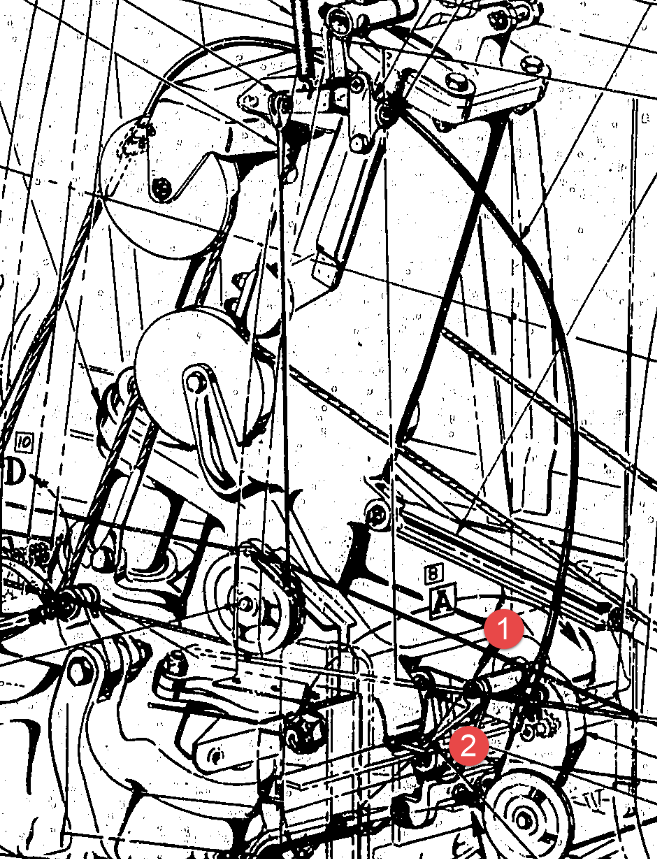
The image on the left shows the cables in this area with 2 key points 1&2 highlighted that are replicated in the 2 archive images. They define the straight section of the cable sleeve that is below and above the cable clips; the locations of which I have incorporated as points in the component sub assembly (last image). This sub assembly does not sit vertically in the assembly, the final position and orientation being determined by other factors which influences the final routing of the cable sleeve.

I have done something similar with the connection at the other end towards the left of the first image. At this stage I now have 4 points that determine the extent of the cable sleeve.

2015-07-23_03-13-17The next step was to go to the main assembly and extract the X,Y,Z coordinates of the four points from the fitted components.

I first select these and run a visual basic routine to extract the coordinates of each point and create a csv file which I import into excel which in turn is imported into a separate Cad part file.

It was then simply a case of running a spline through all four points and sweeping the sleeve profile.

The great thing about this is that the coordinates are relative to the origin of the main assembly so when I import the cable sleeve into the assembly I only have to constrain to the origin planes and it fits perfectly.

2015-07-23_03-23-16The cable itself will be done later in a similar manner which would be added to the sleeve part file as a multi part item or sub assembly using the sleeve centre line as part of the routing.

So no adaptivity, no complex pipe or cable routing just simple association through coordinate translations. The parameters of the sub assembly can be linked back to a spreadsheet so if the route changes I just re-extract the point coordinates and update the spreadsheet, which in turn will update the model.

To me this is a very tidy solution and maintains the integrity of the modelling hierarchy in accordance with the NAA register.

Using additional content in part files to facilitate other activities is very useful for examples like this and in fact any part that is associated with piping or cabling systems, particularly where you have cable clips or supports that need to be considered.

I should note that the extent of the cable sleeve is not exactly as shown in the first image due to the termination part not yet being modeled so I used something that was close at hand to demonstrate this principal.

If you would like a copy of the VB routine then please drop me an email and I will send it onto you.