Grumman Goose: Hand Crank Gearbox
It is not common for blueprints to be almost illegible, and without a Parts catalogue, understanding the mechanisms and operations of assemblies like Gearboxes can be challenging. This was the case with the Tail Wheel assembly I built for the P-51 Mustang and, of course, the current work in progress, Landing Gear Hand Crank Gearbox for the Grumman Goose.
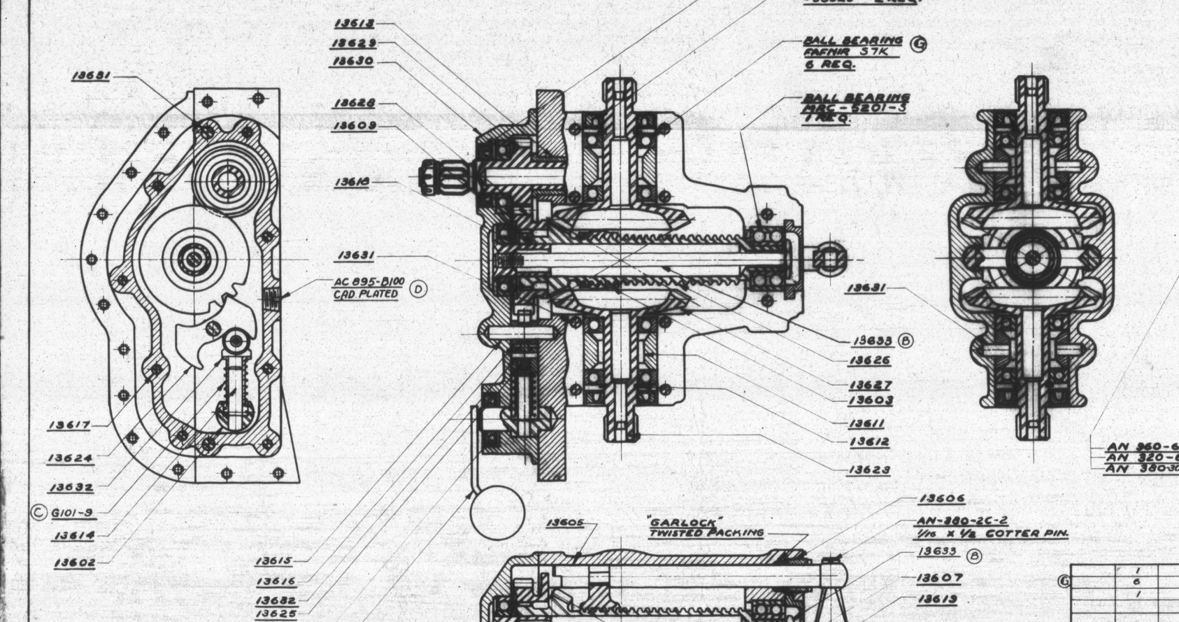
I became captivated by this unique gearbox upon discovering its remarkable dual function: it not only raises and lowers the main landing gear but also manages the tail wheel’s movement. However, delving into the blueprints left me with more questions than answers regarding its intricate operation. Intrigued by its complexity, I decided to construct a working model and evaluate its operational characteristics firsthand.
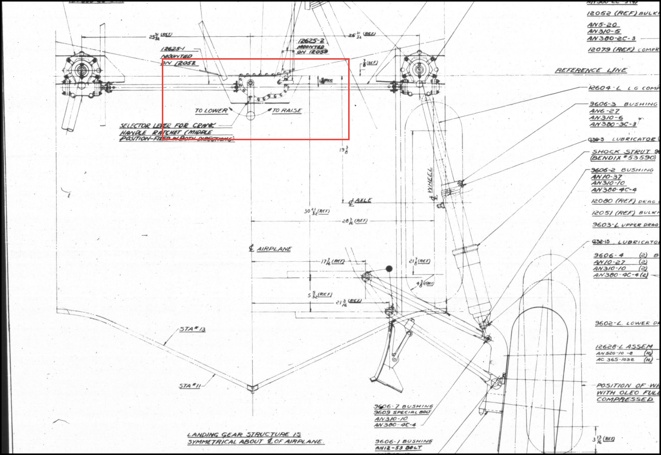
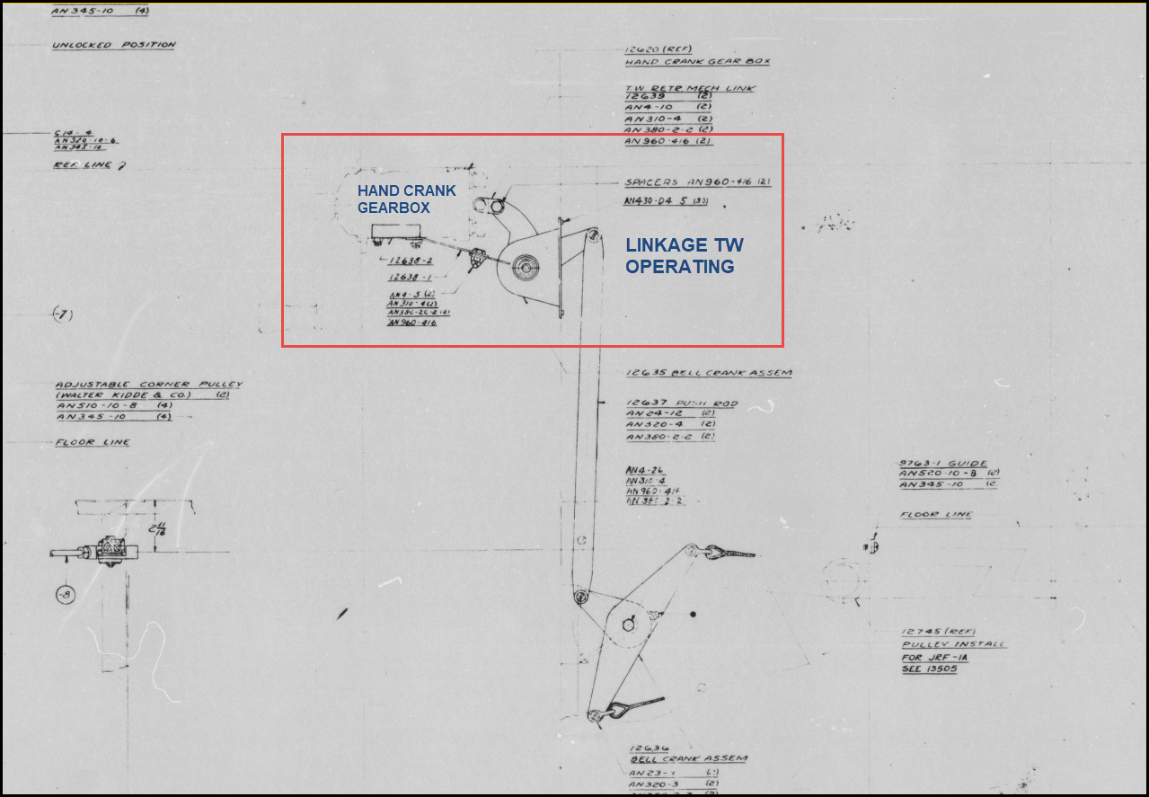
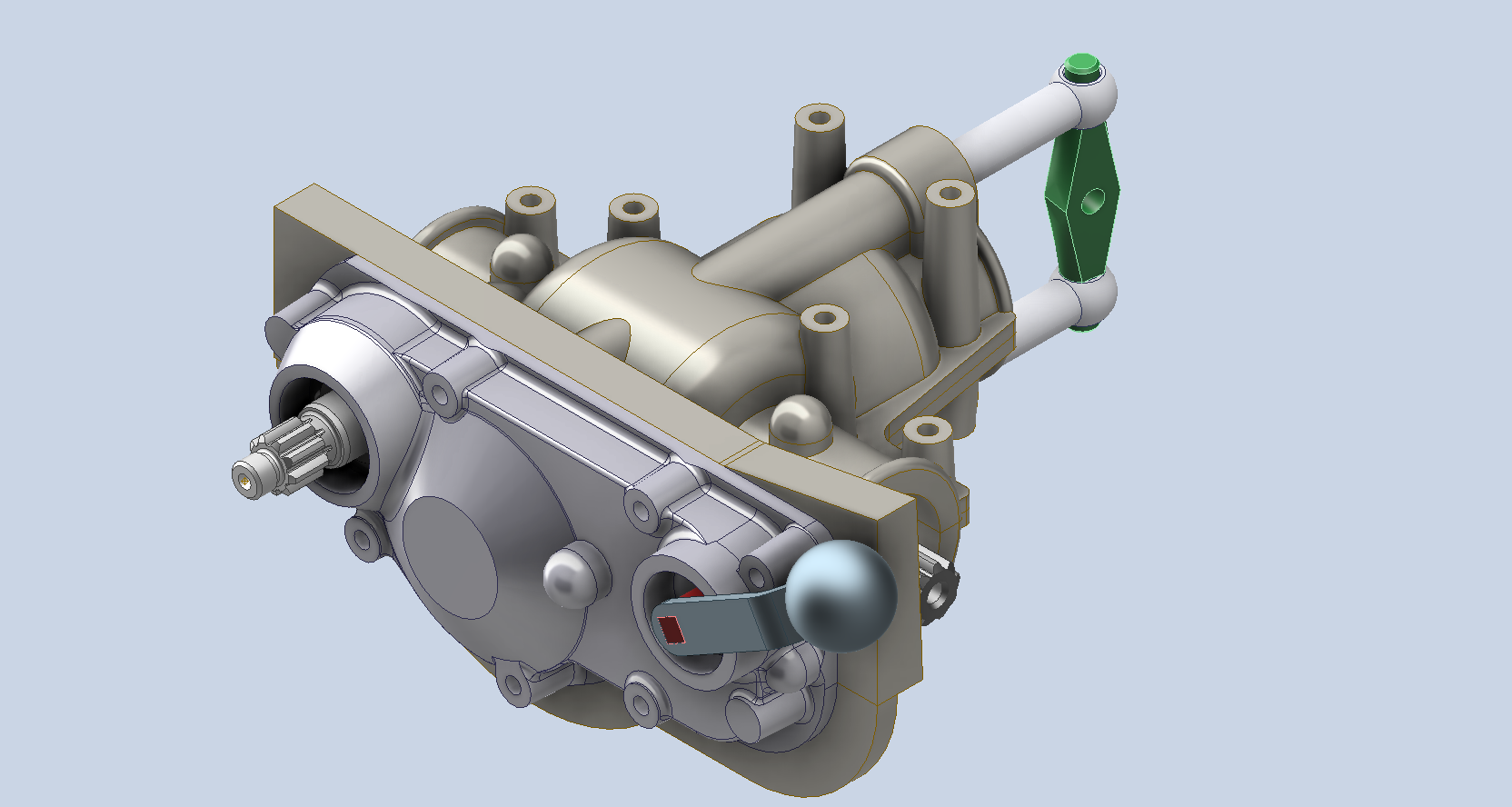
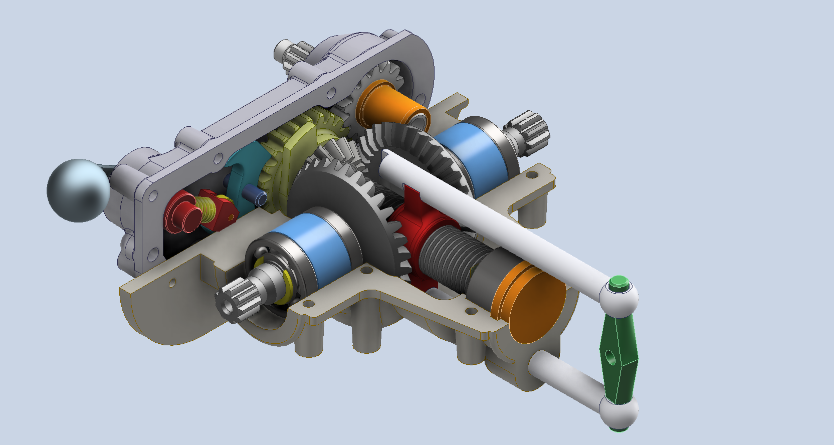
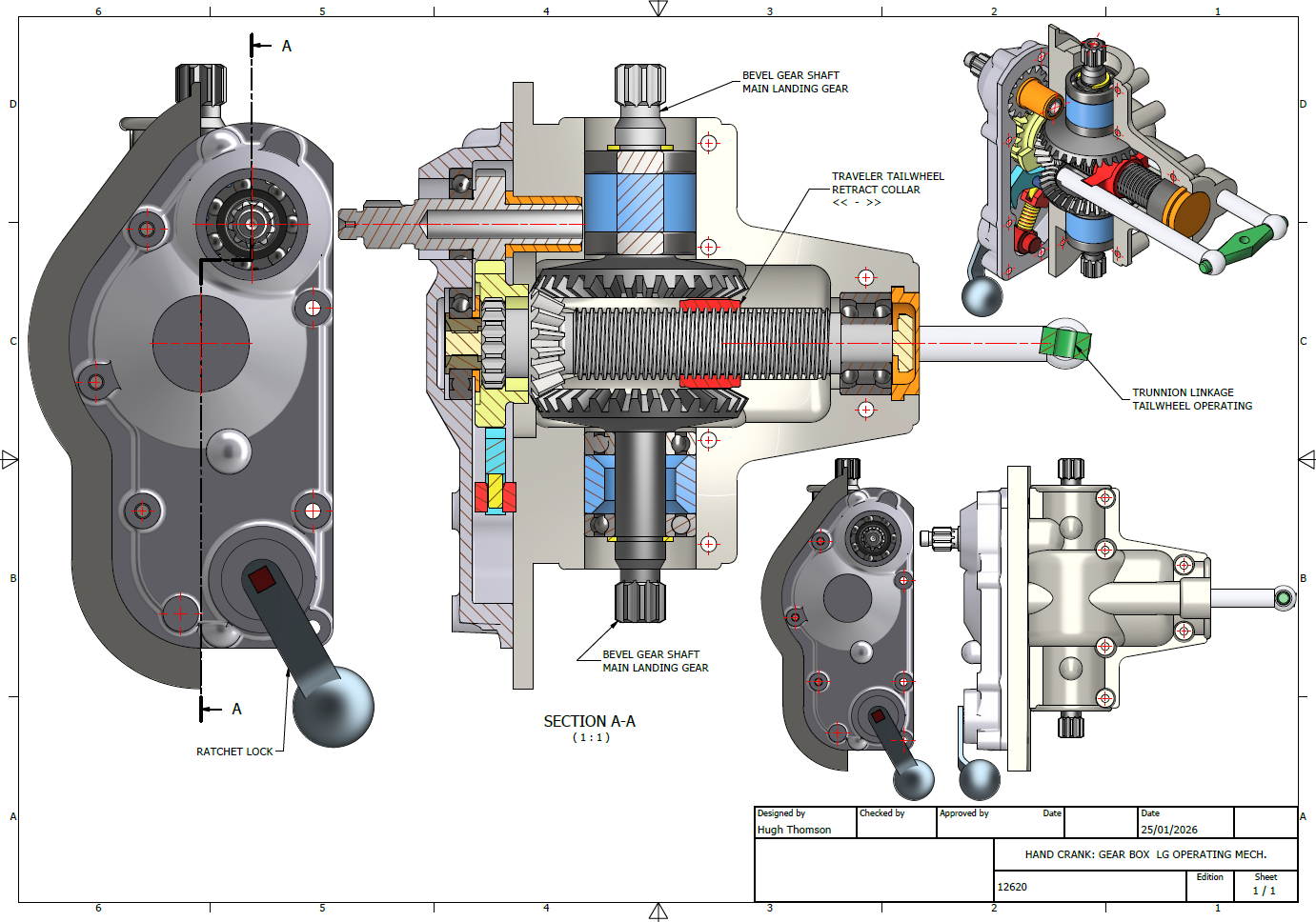
The Gearbox consists of a central shaft featuring an ACME thread along which the Traveler Collar for the tail wheel moves. Additionally, it includes a bevel gear that powers the main landing gear struts, as illustrated. At the base, the ratchet lock offers two positions: one for raising and the other for lowering the landing gear.
I am eager to explore the operational parameters and the criteria for calibrating this gearbox to ensure smooth operation and timing. The available blueprints and installation manuals do not clearly outline how this setup is configured, so I will need to rely on some trial and error.
To successfully complete this assembly, we still need to finalise several crucial details, particularly the assortment of nuts, bolts, and washers. Fortunately, I have access to an extensive library of parametric parts, ensuring that I can efficiently source the exact specifications required for this project.
Developing these assemblies requires a significant investment of time and effort, but I believe this investment is invaluable. Often, manufacturers’ documentation is either unclear, incomplete, or entirely absent, which can create challenges for maintenance and operational staff. By constructing detailed CAD assemblies, we create a visual representation that not only clarifies the intricacies of the components but also serves as a critical resource in the field. This practice can facilitate more efficient troubleshooting, enhance understanding of the system’s functionality, and ultimately improve the overall safety and effectiveness of operations. By proactively addressing these documentation gaps, we ensure that maintenance teams are better equipped to perform their tasks with confidence and precision.
In previous articles, I shared my aspirations to develop a 1/16th scale RC model based on this project. I realised that this gearbox configuration could serve as inspiration for creating a scaled version that would operate using a single servo to raise and lower the model’s main landing gear and tail wheel.
Update: 28th Jan 2026: Spur Gears
The Spur Gears and Splines dimensions are shown as “over pins”, the diameter of which are 0.140 in.
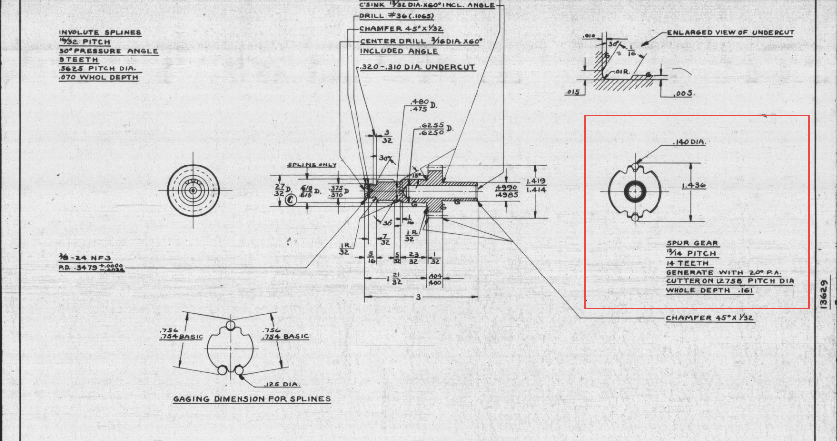
CAD software generally does not facilitate this type of dimensioning for gears, so first we have to determine the important gear parameters using online calculators like this one at Zakgear.com:
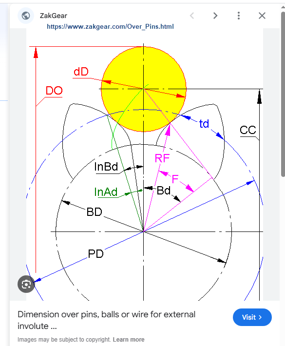
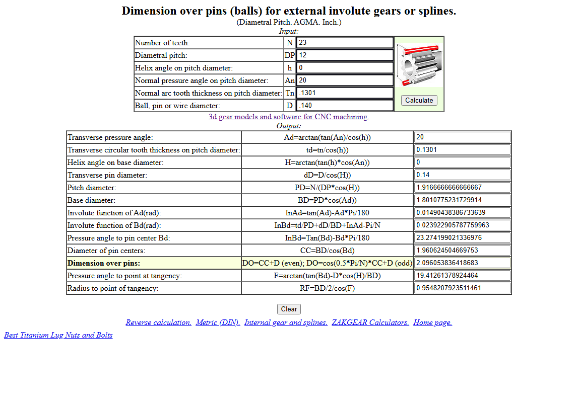
The Diametral Pitch is 12 (number of teeth/pitch diameter), which we then input into the CAD gear calculator. To match the calculated diameters from the Zakgear website, we need to adjust the Addendum to 0.800.
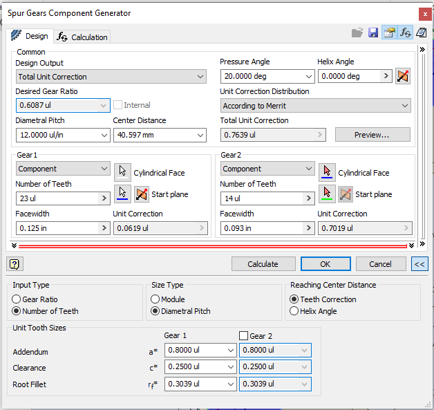
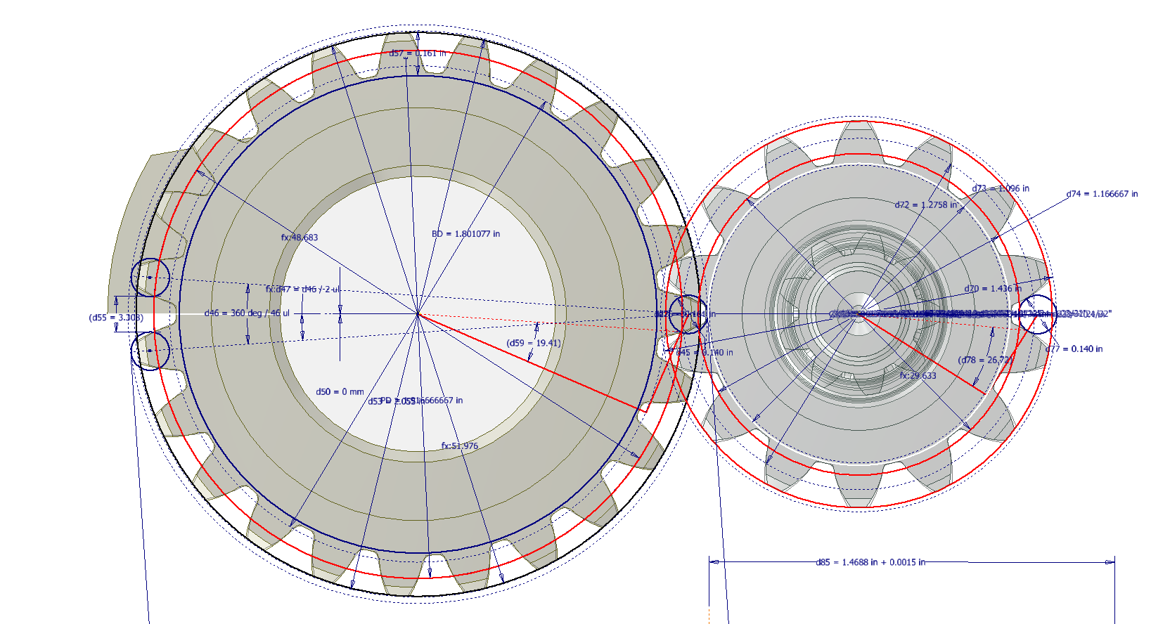
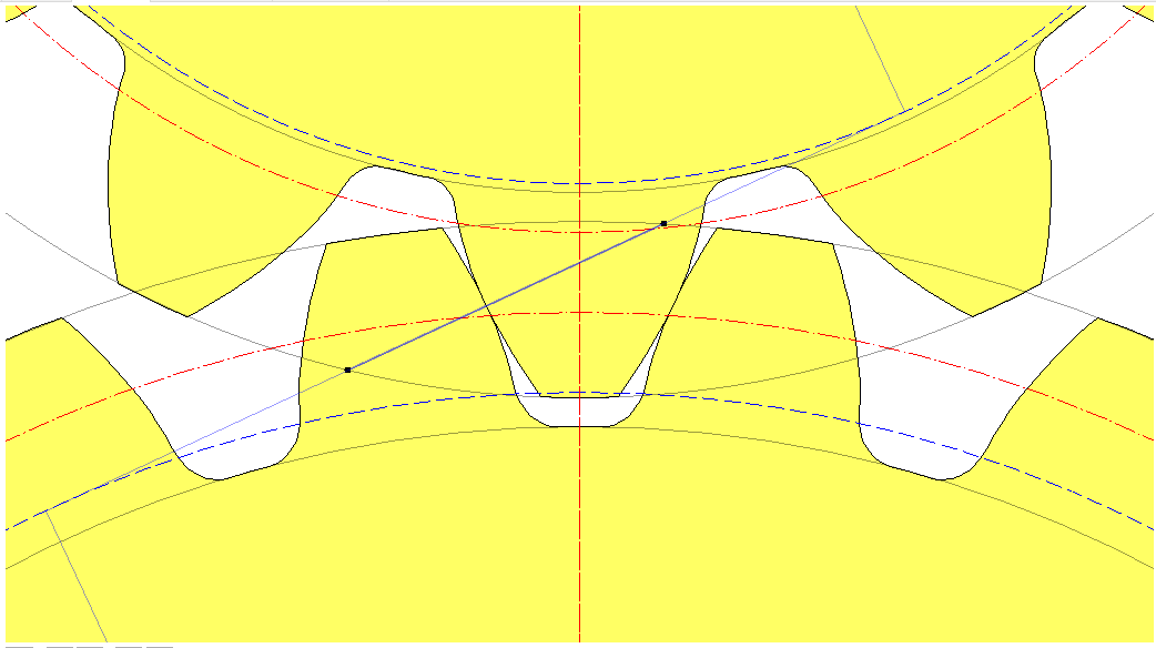
By overlaying the CAD data onto the Zakgear data, we achieve a good match. It may only require microdimensional adjustments within stated tolerances to ensure perfect alignment for a correct setup.


I was investigating the landing gear boxes on a Grumman Goose. I am the owner of N703 seen at http://www.goosehanger.com. I ran across your work on the tail wheel yoke. I have one on the shelf if you would like to take a close look. I could ship that to you if you would agree to ship it back when done looking at it
I am interested in the gearboxes. I would particularly like to know where they came from, the manufacturer, and the original application. I believe that Grumman bought these off the shelf and did not design or manufacture them. I am interested in both the left and right gearbox ( which are the same of course) and the center gearbox. If you have any information that would be of assistance in this matter, I would appreciate having it. Thank you for any assistance and if you would like the tail wheel yolk to be shipped, please let me know. John Pletcher 907-229-4698; grumman703@gmail.com.
Hi John; Thank you for your inquiry. The Grumman drawings for the Gearbox are comprehensively detailed for the casing and internal components, sufficient for manufacture. Normally where a componenet is manufactured externally we would only have a drawing with basic details for installation and maintenance. The Cylinder on the landing gear assembly for example is a contracted item and therefore the Grumman blueprint only references the item for installation and where applicable bespoke mod. It may be that the gearboxes are made elsewhere; I can’t say for sure; but the drawings are fully detailed, sufficient for manufacture.