
Subscribe to continue reading
Subscribe to get access to the rest of this post and other subscriber-only content.
Subscribe to get access to the rest of this post and other subscriber-only content.
Technical Support:
I regularly receive technical support requests in my email inbox, and I value the opportunity to assist a diverse range of clients, including museums, restoration groups, and individuals. Each request presents a chance to share knowledge and provide effective solutions.
The inquiries encompass a diverse range, from complex technical details crucial for parts manufacturing to basic questions about the CAD and ordinate datasets that fuel innovation. If I can respond to these queries quickly and easily, I will do so. However, if addressing them requires extensive research and development, I will need to prioritise my efforts accordingly.
Priority is given to those who actively support my work via donations and those who have helped with research, often from museums and restoration groups. It is often the latter that drives my current workload; this is the reason why I may shift focus from one aircraft project to another.
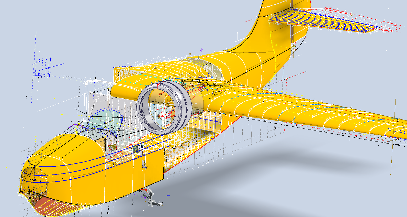
For example, I was recently working on the Grumman Goose CAD updates to fully surface the model when I received a request from a long-time supporter to develop the Nacelles and Cowl for the B-25. This development requires intensive research because many of the elements are not fully located by Station references or datums. So I have to build the individual parts one piece at a time and assemble them to determine the true locations of the many sub-assemblies.
The B-25 CAD/Ordinate package contains all known ordinate dimensions based on the original blueprints. However, I am aware that there is additional ordinate data available for the nacelle and cowl, but the blueprints for these parts are currently inaccessible. I have reached out to various organisations to obtain a copy, but this process may take some time. In the meantime, I will work on developing the nacelle and cowl one piece at a time to create a fully detailed model for inclusion in future datasets.
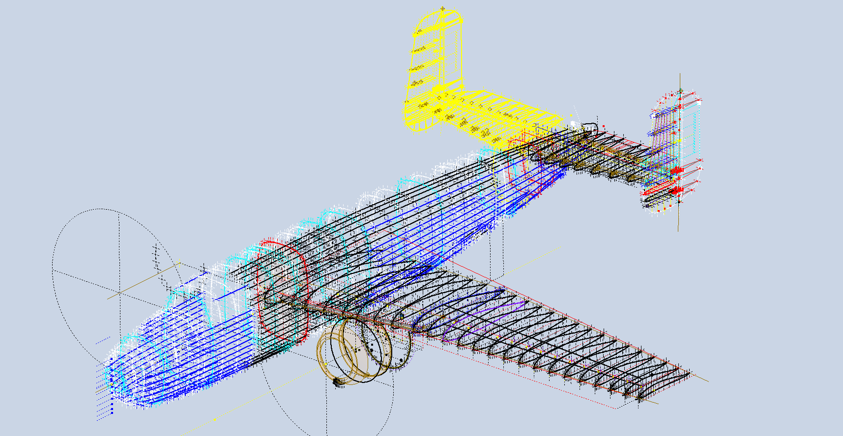
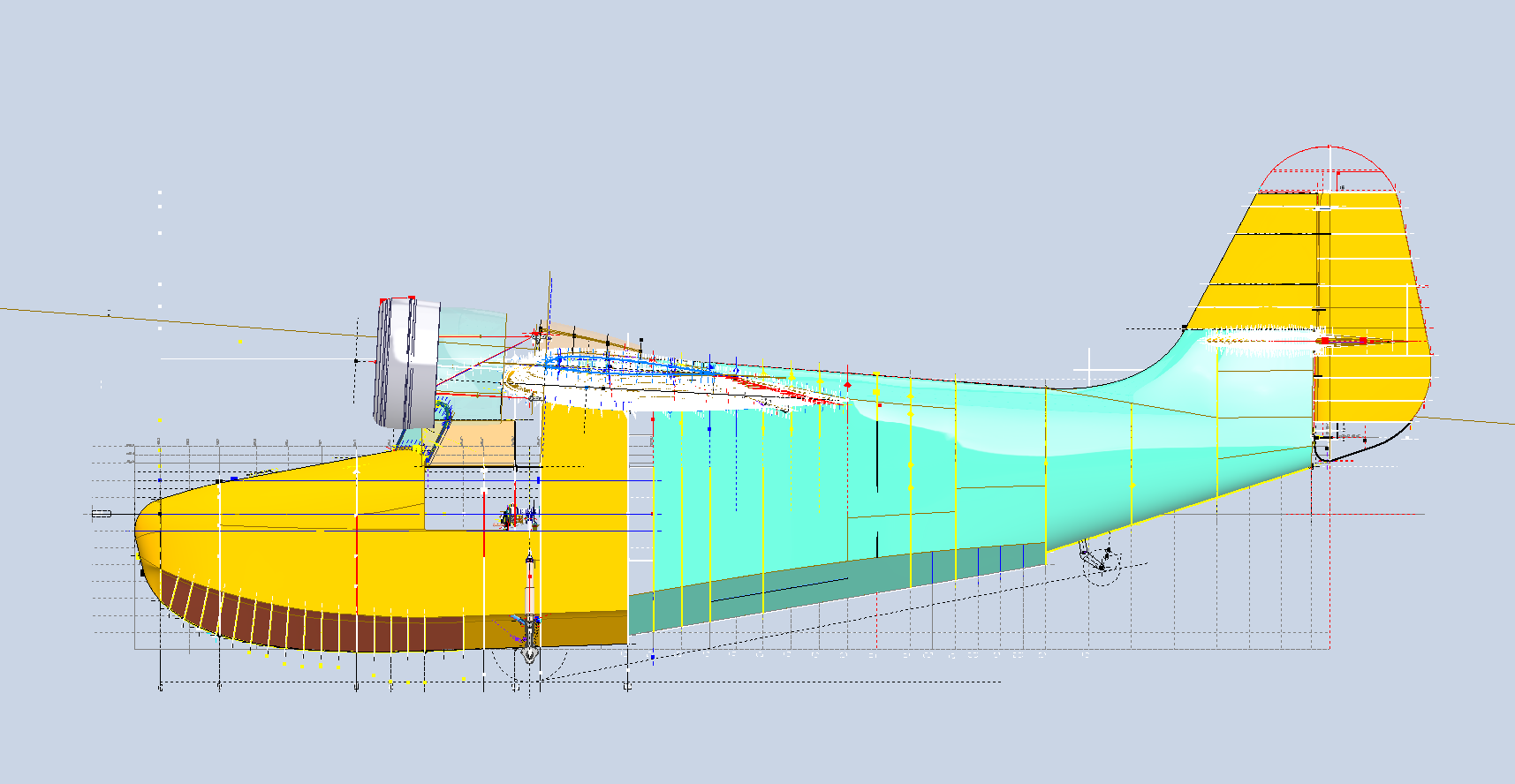
By the way, the green section for the Grumman Goose is a complete restructuring of the rear fuselage following some updates on the original data. I will get back to this project shortly and complete the surface modelling and finalise the undercarriage and cabin.
I appreciate your inquiries and will do my best to respond as promptly as possible. If there is a delay in my response, I kindly ask for your patience, as I focus on assisting active patrons first. Thank you for your understanding and support!
Please consider making a small donation… every dollar helps. Thank you.
Subscribe to get access to the rest of this post and other subscriber-only content.
The Real Value of the CAD/Ordinate Datasets: Often Overlooked!
For many of my aircraft projects listed on the CAD+Blueprints tab, I offer comprehensive datasets of ordinate dimensional data in inches and millimetres listed in Excel spreadsheet tables. This data is extracted directly from original blueprints, verified by development in CAD, and, in many cases, verified by accurate recalculation.
This is the real value of these datasets, many of which took days or even weeks to compile. As an Excel spreadsheet, the X,Y, Z data is easily cut and pasted into your CAD system of choice, instantly providing point datasets that define fuselage frames, wing ribs, cabin contours and so on. It is that easy and saves you many days and weeks of trawling through blueprints and extracting the data piece by piece yourself.
The format of the tables replicates the same layouts as the data presented on the original blueprints, where applicable. So the data is easily cross-referenced for verification.
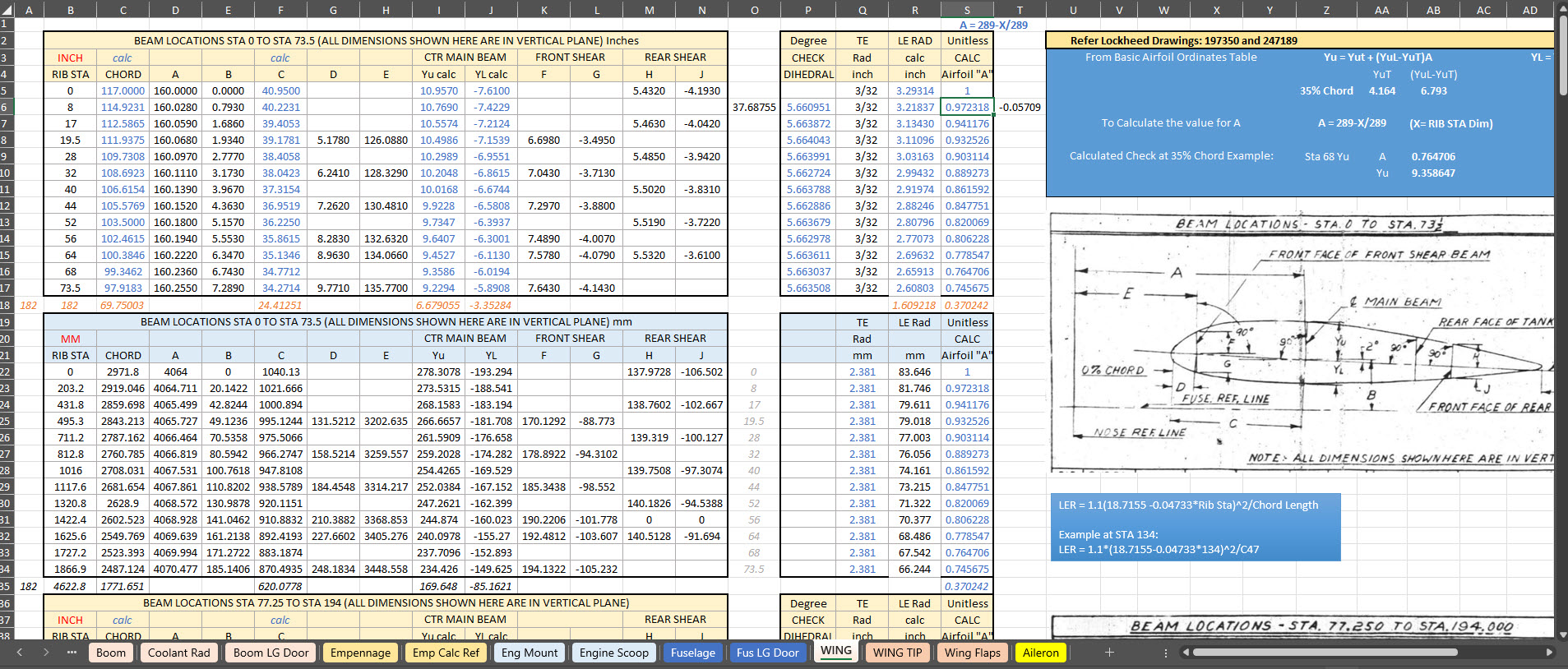
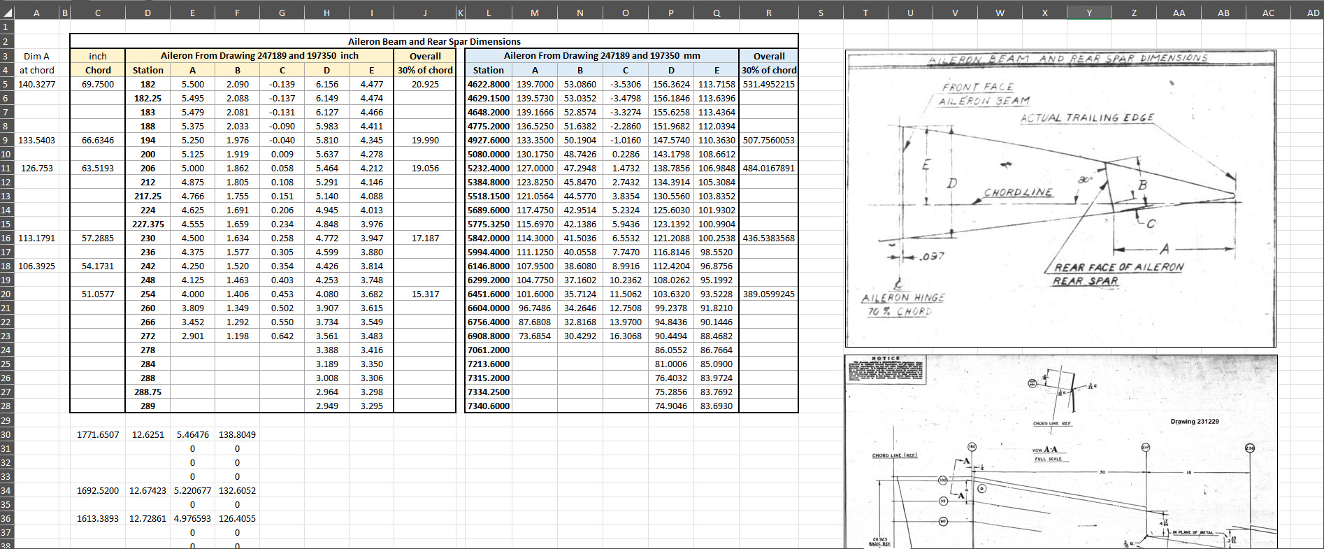
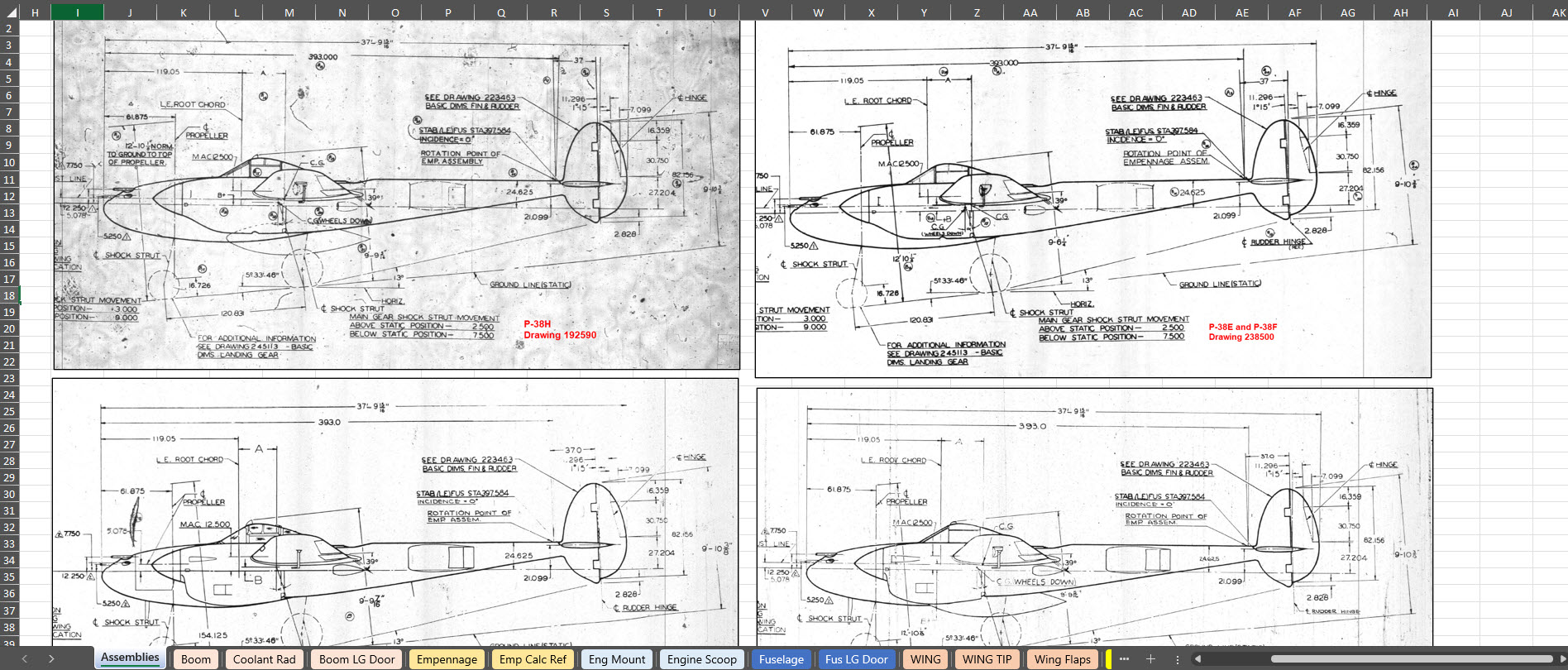
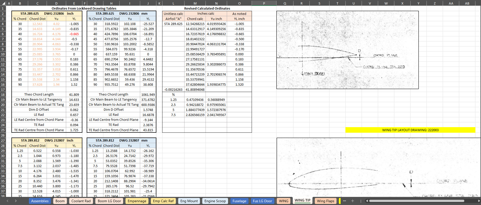
To give you a clearer picture of what to anticipate, the screenshots above showcase typical coordinate datasets for the P-38, presented in an Excel spreadsheet format. These datasets feature organised columns and rows, making it easy to navigate through the intricate details associated with the P-38’s specifications and performance metrics.
There is one caveat: there is a small cost involved. I have overhead expenses for software licenses and for running this blog Ad-free. I rely on donations and the sale of datasets like this to help cover those ongoing costs.
The Excel spreadsheets provided are fully adaptable and not restricted in any way, allowing you to modify them to meet your specific needs.
I wanted to take a moment to share this brief article that emphasises the true value of the CAD/Ordinate datasets. My aim is to shed light on how these datasets can be instrumental in enhancing your project and productivity. With their rich features and detailed information, the CAD/Ordinate datasets can provide invaluable insights and support, making your work not only more efficient but also more effective.
All datasets are supplemented with CAD models derived from them in commonly used formats, such as DWG, to assist you further.
Technote: Clean Up 3D Scans:
In 2019, I wrote an article about my experiences using photogrammetry and its applications in historical aviation research. For those interested, the article can be found here: Photogrammetry. Having delved into this fascinating subject over the years, I thought I should share some tips and associated YouTube videos that can help with the preparation of scans for 3d printing.
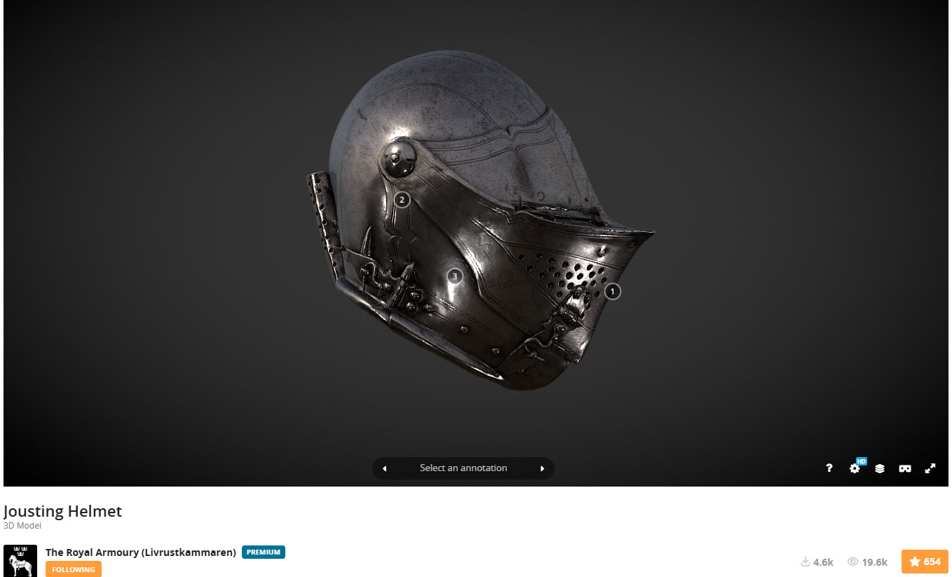
Museums often embrace exciting scanning techniques to safeguard their precious artefacts, such as the cutting-edge use of laser scanners and the fascinating method of photogrammetry. These innovative approaches not only help preserve history but also bring it to life in new and captivating ways! You will find many museums on sites like Sketchfab with large collections of these artifacts availble for download.
You might be curious as to why the first two links lead to websites featuring armoury models. In addition to my personal interest in armour and weaponry from the Middle Ages, this subject also illustrates the typical surface profiles similar to those of historical aviation aircraft and their components.
In today’s world, nearly everyone carries a mobile phone, and many of these devices come equipped with high-resolution cameras capable of capturing stunning photographs. This feature proves especially beneficial for those interested in photogrammetry projects, which require detailed imaging to create accurate 3D models. Using a mobile phone for this purpose is particularly advantageous when visiting museums, as it allows for discreet photography without disrupting the exhibit or disturbing other visitors. This non-intrusive method enables enthusiasts and professionals alike to document artefacts from various angles, enhancing their ability to analyse and reconstruct their dimensions digitally.
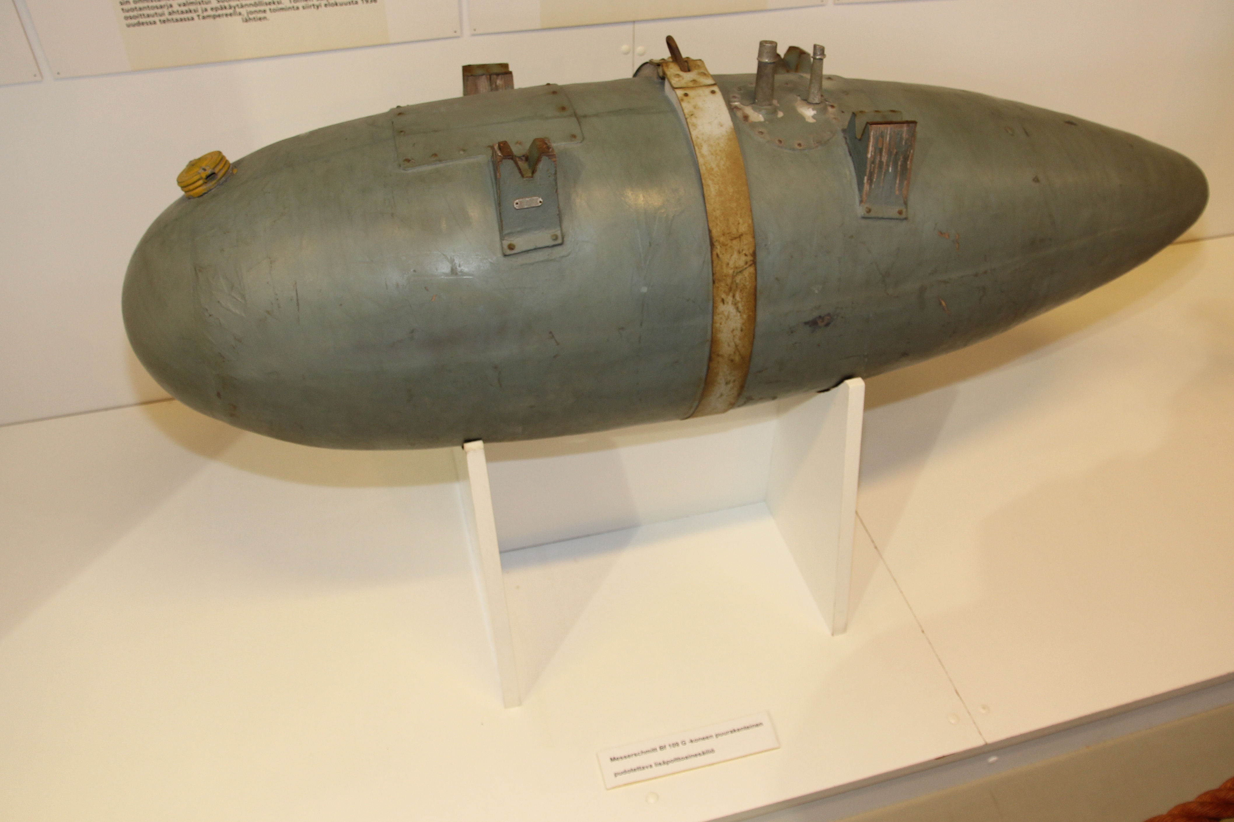
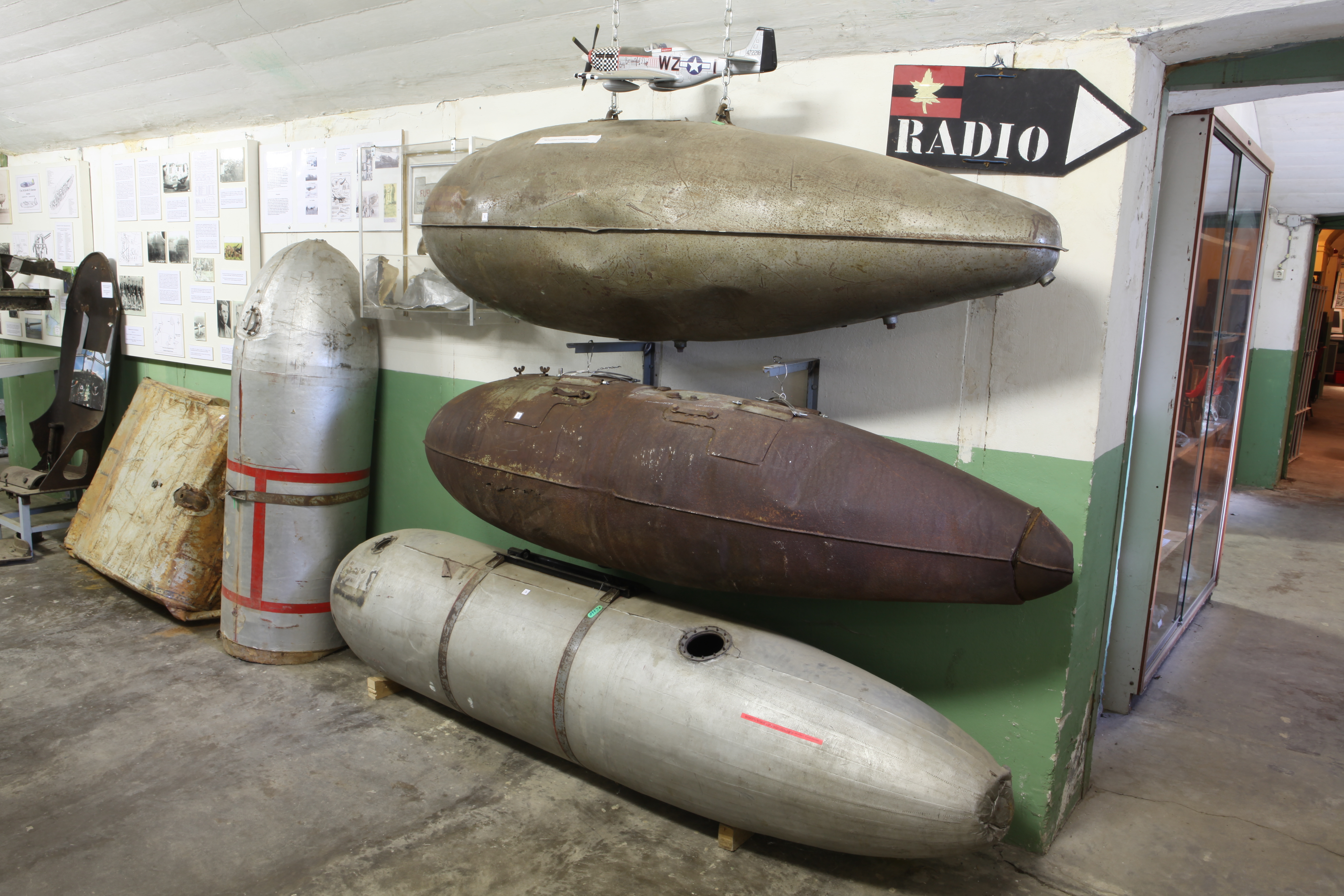
One of my favorite subjects to capture in photogrammetry is droptanks. They are often rusty, making them ideal subjects for this technique. Other great items to consider include guns, torpedoes, and aircraft engine cowls. While you may not have complete access to all sides of a cowl, remember that you only need half of the profile to recreate it effectively. It is also a good idea to carry with you a plastic ruler that you can use for scale later.
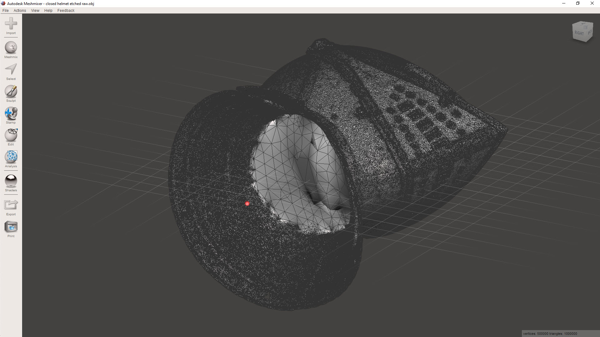
Getting back on subject to cleaning those scans, let me introduce you to the Jousting helmet.
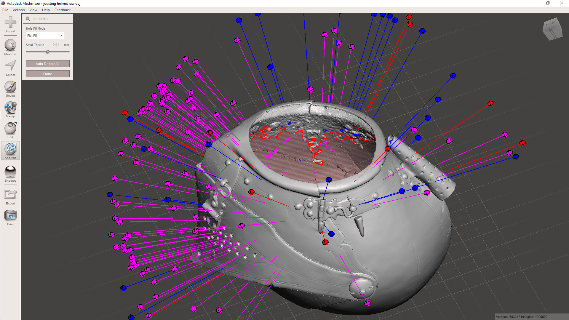
My workflow starts with the Inspector feature in Meshmixer, a free download from Autodesk. This will throw up a bunch of different issues, as illustrated. The blue refers to small holes or inverted faces, the red are potentially problematic areas for resolving, and the magenta identifies loose, unattached meshes. At this stage, you could just run the Auto Repair All, and Meshmixer will do its best to resolve those highlighted issues. Sometimes, though, the results can be unpredictable and may add additional meshing that you don’t want.
Don’t despair, as you can be selective with this tool and initially fix the blue-highlighted areas by clicking on each of the blue orbs. You could click through each of the magenta orbs and select each of the unattached elements one at a time, but there is a better way.
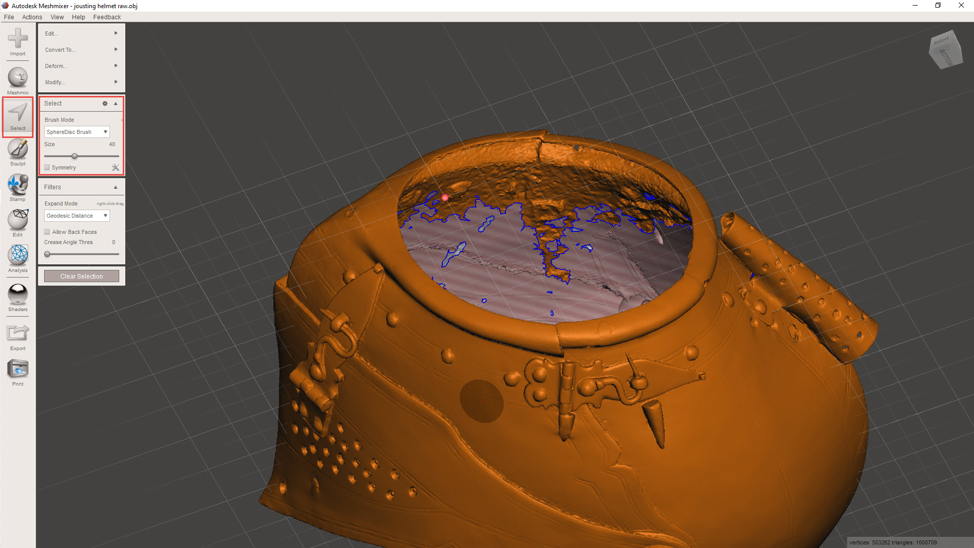
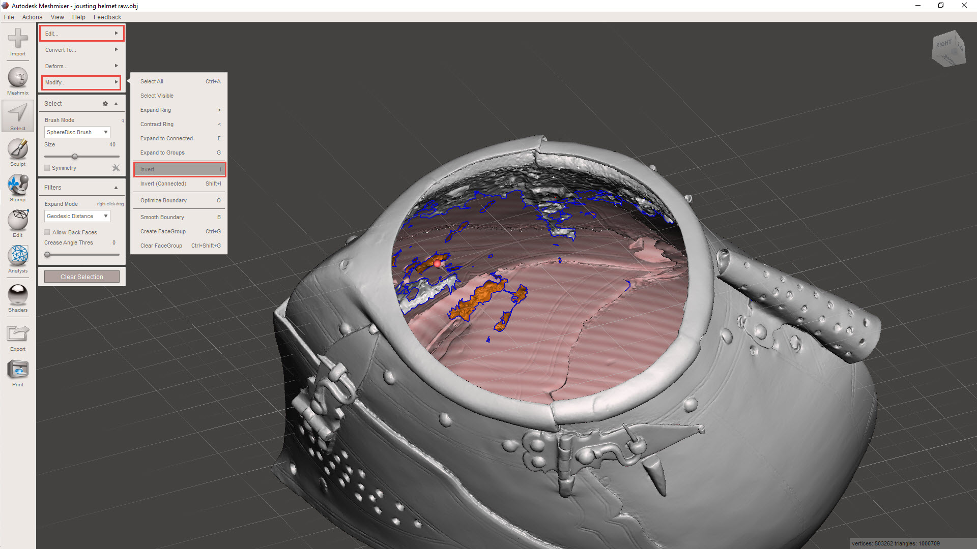
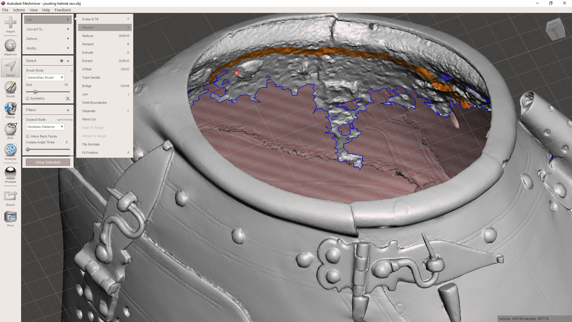
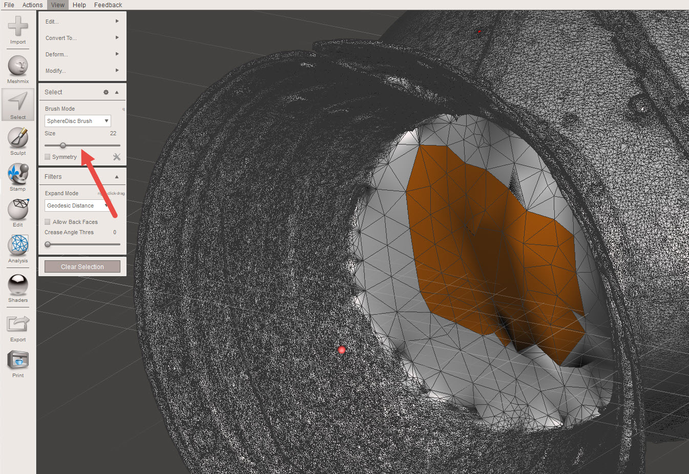
Using the select option, we can isolate the unattached elements quickly and efficiently. First, select an area using a medium-sized brush and double-click to select all attached meshes. A single mouse click will only select mehes within the specified brush diameter. Once selected, go to MODIFY>INVERT to invert the selection to group the unattached items. Then go to EDIT>DISCARD to remove all those unattached items.
This is also a useful technique for tidying up groups of meshes.
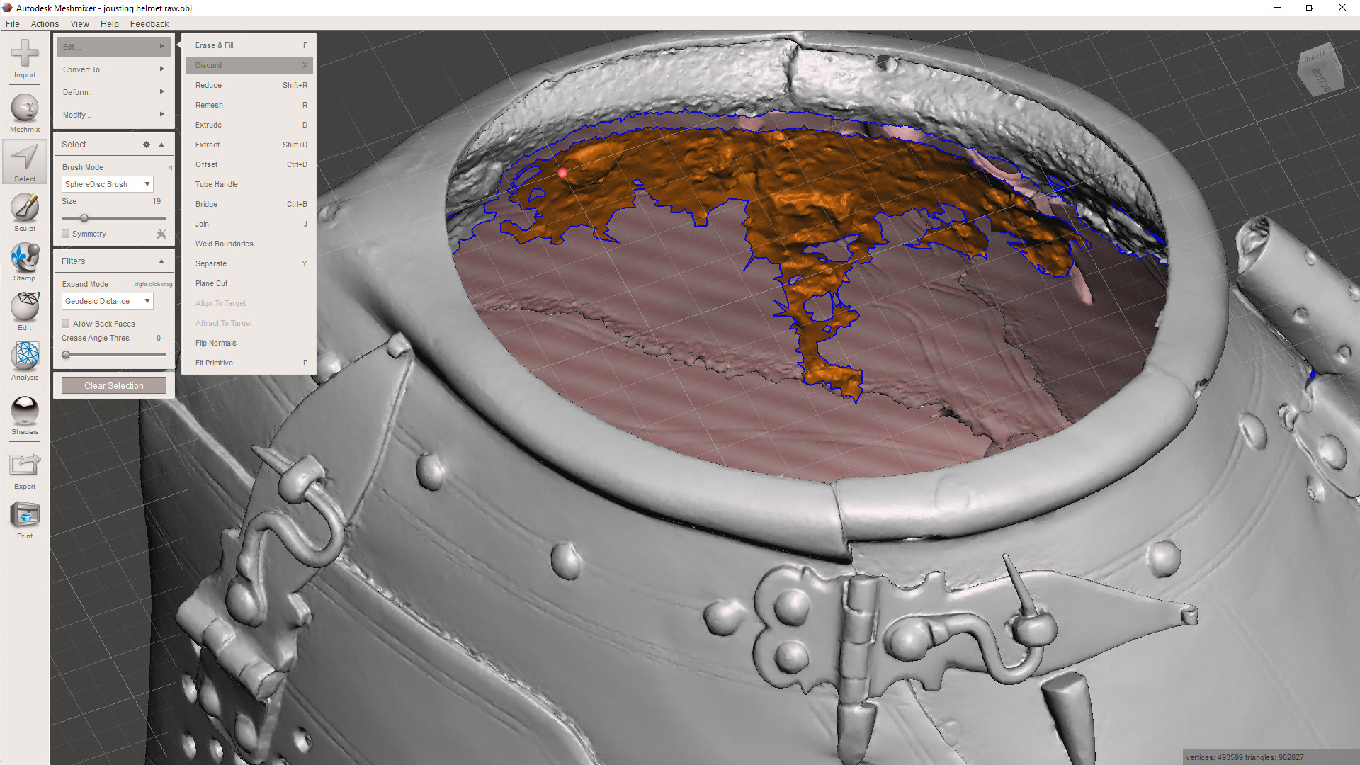
Here, I have selected a row of meshes, essentially a channel cut line isolating the chaotic mass of meshes. Using the above technique to then select the entire body and invert, I can easily remove that mass. Taking my time, I would go around the interior and tidy up the spurious collections of meshes one mass at a time.
For reference, a good YouTube video explaining this in more detail “Meshmixer Clean a Scan”
Sometimes with photogrammtery the conversion programs will attempt to enclose large areas, commonly the base or unscanned regions.
If you need to remove sections like this, selecting the meshes directly and discarding works fine, but you can also just create a perimeter channel, invert and discard accordingly.
Ultimately, we desire a continuous, defect-free surface suitable for applying thickness for 3D printing.
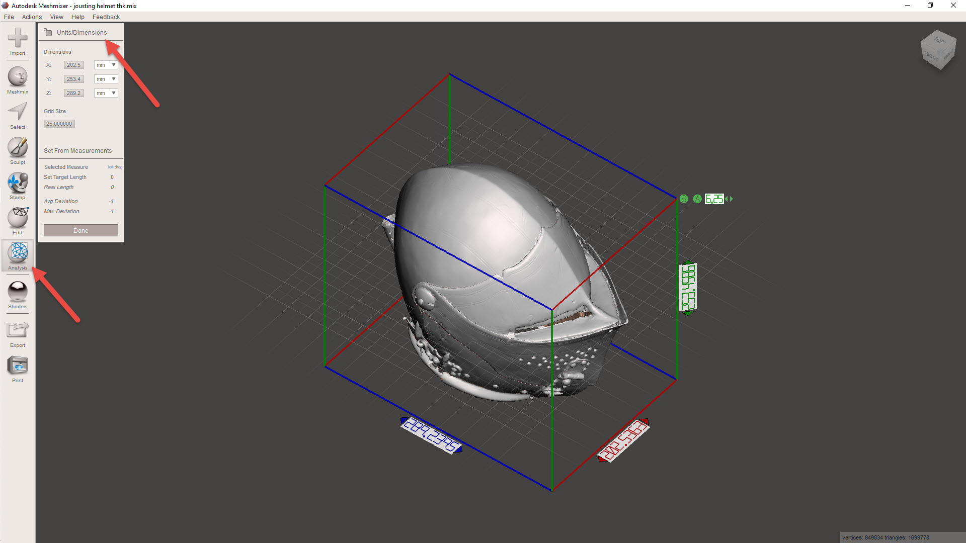
Before we apply a material thickness, we need to be sure the object is correctly sized. First, we need to identify the actual size of the imported model using the INSPECTOR> UNITS/DIMENSION command. Then go to EDIT>TRANFORM to scale the object to the desired size. For this example, I kept the size within the boundary limits of my 3D printer.
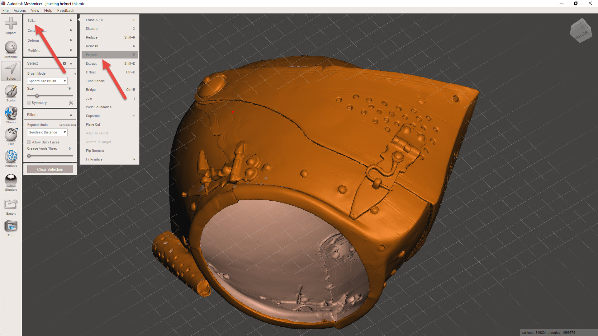
For wall thickening, usually a minimum of 1mm is the recommended value, but for this example, I set it to -0.8mm (twice the nozzle size), and it printed just fine. The thickness is applied using the SELECT>EDIT>EXTRUDE combination, and be sure to select “NORMAL” and “OFFSET”. Don’t go crazy with the wall thickness, as any interior surfaces will thicken accordingly and may exceed the gap between the inside and exterior faces, causing some odd surface anomalies.
Export the model to STL, and it should be ready for 3D printing. Sometimes the walls may be thinner than expected due to the process described, in which case, be sure to have the Thin Walls option selected in the slicer.
Identifying Interior Meshes:
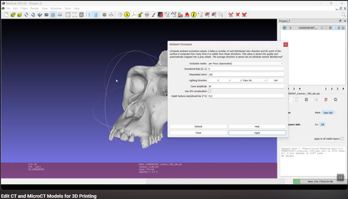
This may or may not be relevant, but sometimes when tidying up models from a third party, you occasionally find combined models with a lot of interior surfaces. There is an interesting video showing you how to fix this using Ambient Occlusion in Meshlab by Terry Simmons-Ehrhardt
The End Goal:
After creating a tidy meshed model, you can import it into CAD, in my case, this would be Inventor. This model can then be used to generate contours for further CAD development.
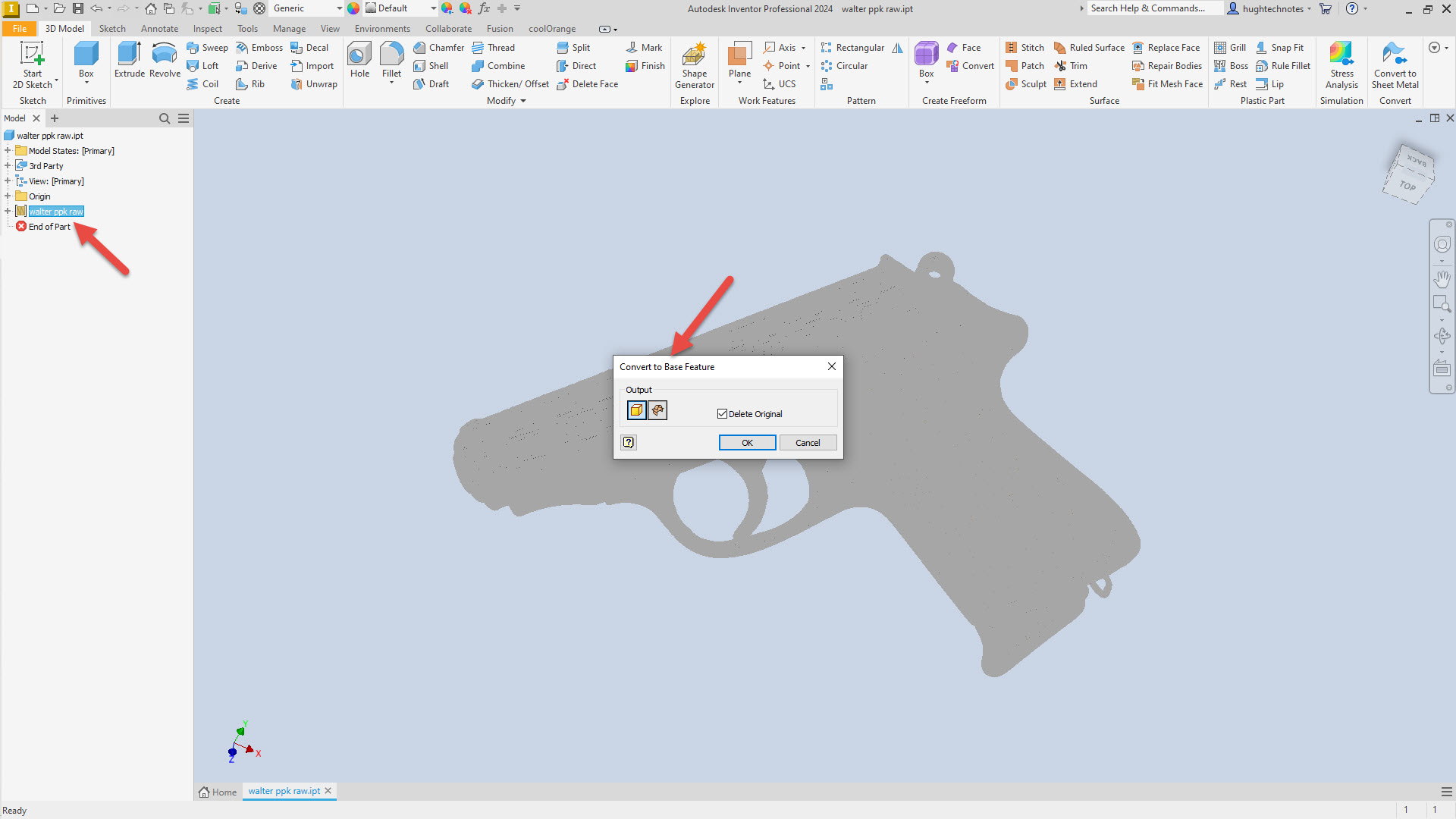
For this example, I have imported the Walter PPK scan. When using Inventor to work with scanned STL or OBJ files, the model must first be converted to workable surfaces or solid models after import. Autodesk Inventor uses a 3rd party add-in called Mesh Enabler, which is availablehere. Fusion also has the capability of working with imported scans, which does not require any special add-ons.
When selecting the type of conversion, always select the Solid option. Even though it may fail to compile a solid first time around, it does give you standard surface meshes to work with. The other option for a composite surface is less workable and occasionally frustrating to work with.
Once you have a solid mass or a workable surface, you can identify key vertices to facilitate contour development for further design.
I chose medieval helmets to illustrate the principles mentioned earlier because they are excellent subjects to practice contour development workflows. They share similarities with aviation subjects and are also engaging to work with.
Grumman Goose: Hand Crank Gearbox
It is not common for blueprints to be almost illegible, and without a Parts catalogue, understanding the mechanisms and operations of assemblies like Gearboxes can be challenging. This was the case with the Tail Wheel assembly I built for the P-51 Mustang and, of course, the current work in progress, Landing Gear Hand Crank Gearbox for the Grumman Goose.
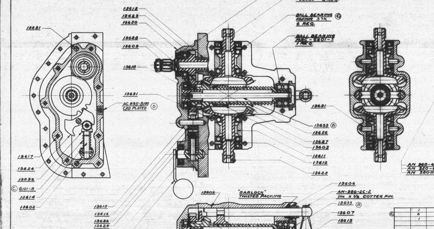
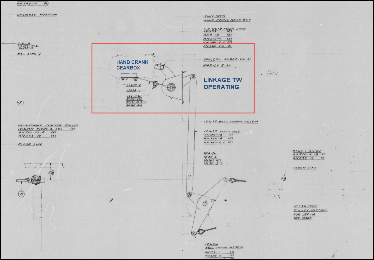
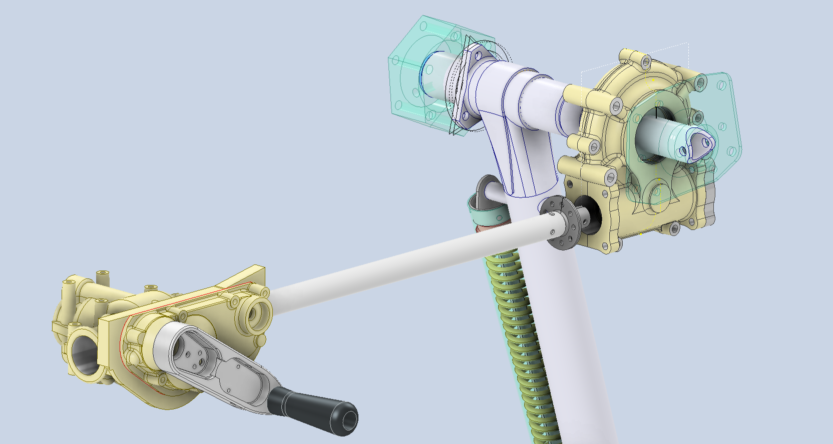
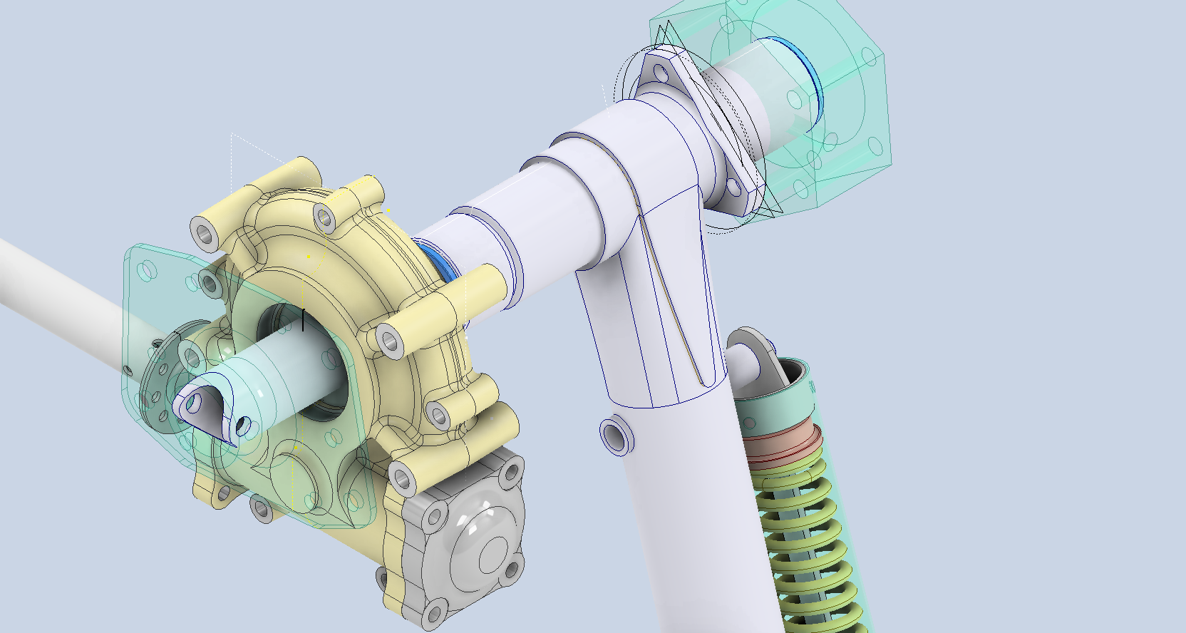
I became captivated by this unique gearbox upon discovering its remarkable dual function: it not only raises and lowers the main landing gear but also manages the tail wheel’s movement. However, delving into the blueprints left me with more questions than answers regarding its intricate operation. Intrigued by its complexity, I decided to construct a working model and evaluate its operational characteristics firsthand.
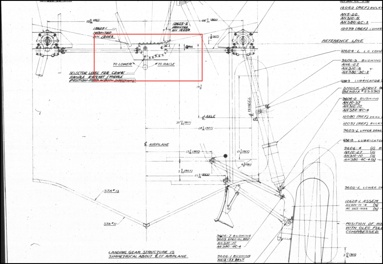
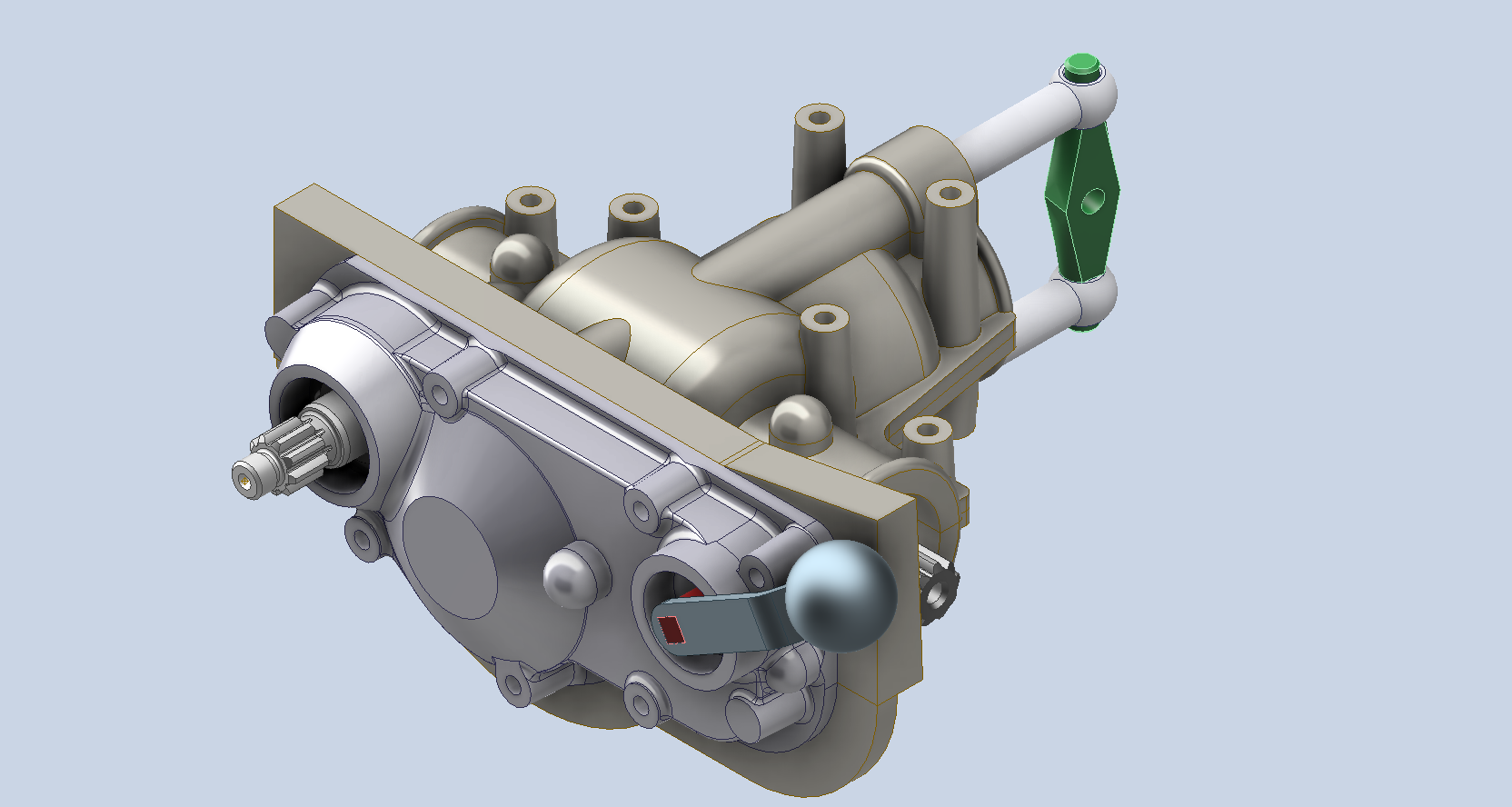
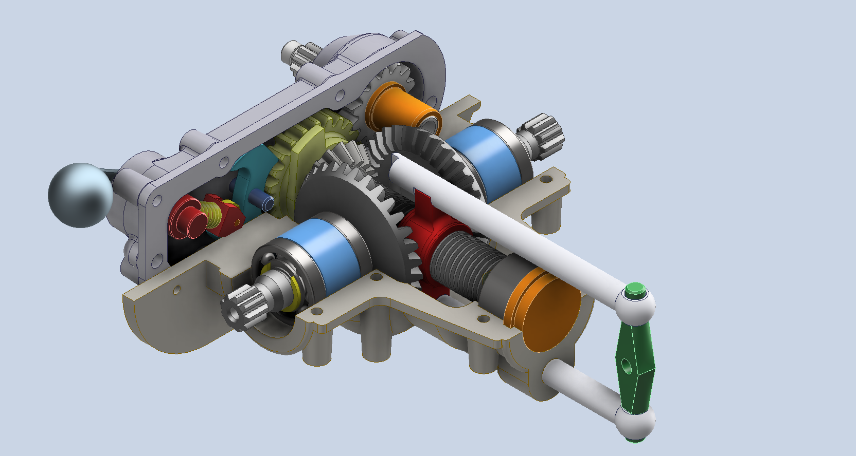
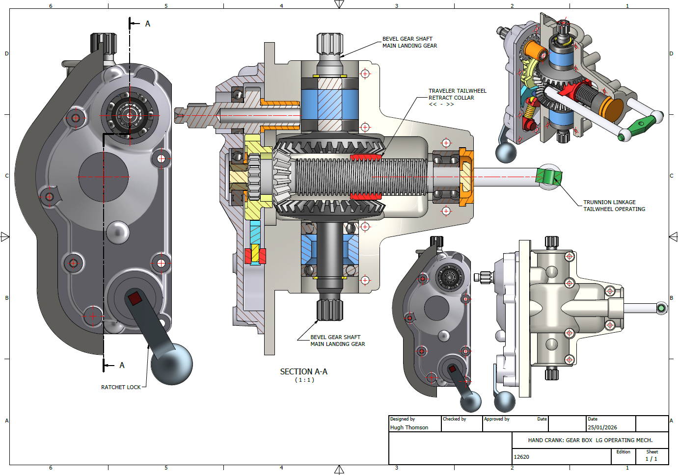
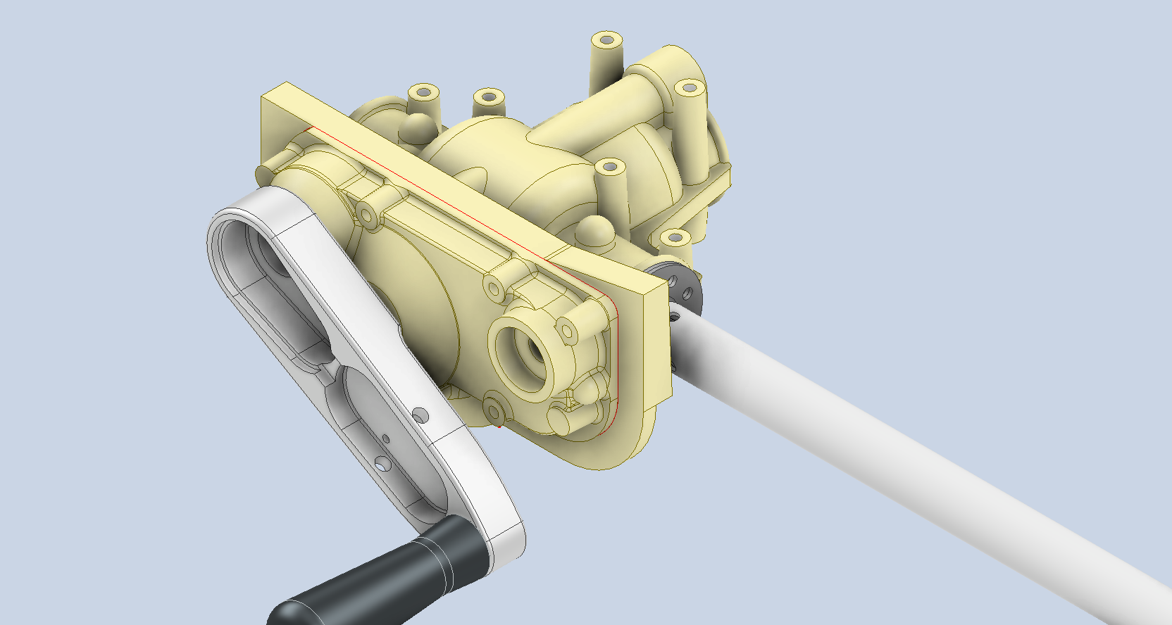
The Gearbox consists of a central shaft featuring an ACME thread along which the Traveler Collar for the tail wheel moves. Additionally, it includes a bevel gear that powers the main landing gear struts, as illustrated. At the base, the ratchet lock offers two positions: one for raising and the other for lowering the landing gear.
I am eager to explore the operational parameters and the criteria for calibrating this gearbox to ensure smooth operation and timing. The available blueprints and installation manuals do not clearly outline how this setup is configured, so I will need to rely on some trial and error.
To successfully complete this assembly, we still need to finalise several crucial details, particularly the assortment of nuts, bolts, and washers. Fortunately, I have access to an extensive library of parametric parts, ensuring that I can efficiently source the exact specifications required for this project.
Developing these assemblies requires a significant investment of time and effort, but I believe this investment is invaluable. Often, manufacturers’ documentation is either unclear, incomplete, or entirely absent, which can create challenges for maintenance and operational staff. By constructing detailed CAD assemblies, we create a visual representation that not only clarifies the intricacies of the components but also serves as a critical resource in the field. This practice can facilitate more efficient troubleshooting, enhance understanding of the system’s functionality, and ultimately improve the overall safety and effectiveness of operations. By proactively addressing these documentation gaps, we ensure that maintenance teams are better equipped to perform their tasks with confidence and precision.
In previous articles, I shared my aspirations to develop a 1/16th scale RC model based on this project. I realised that this gearbox configuration could serve as inspiration for creating a scaled version that would operate using a single servo to raise and lower the model’s main landing gear and tail wheel.
Update: 28th Jan 2026: Spur Gears
The Spur Gears and Splines dimensions are shown as “over pins”, the diameter of which are 0.140 in.
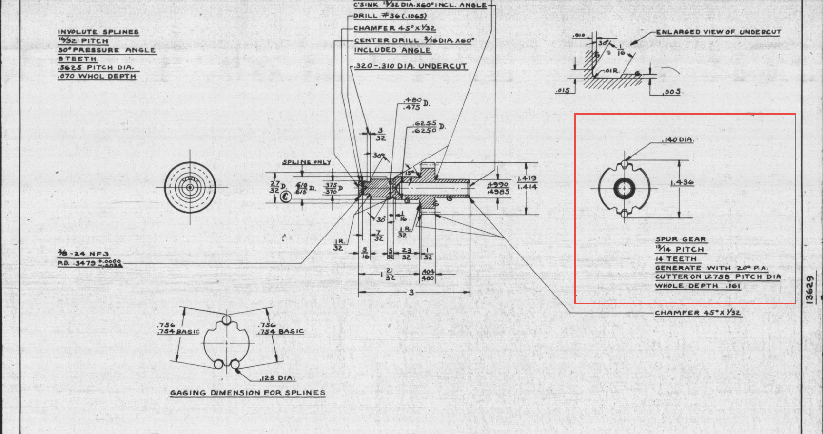
CAD software generally does not facilitate this type of dimensioning for gears, so first we have to determine the important gear parameters using online calculators like this one at Zakgear.com:
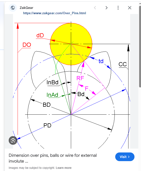
The Diametral Pitch is 12 (number of teeth/pitch diameter), which we then input into the CAD gear calculator. To match the calculated diameters from the Zakgear website, we need to adjust the Addendum to 0.800.
By overlaying the CAD data onto the Zakgear data, we achieve a good match. It may only require microdimensional adjustments within stated tolerances to ensure perfect alignment for a correct setup.
Restoration Insights: The Risks of Working from Blueprints
Restoration projects…is working directly from blueprints a good idea?
A company I know is currently restoring a P-40N aircraft, and I came across several posts where they highlighted concerns about the alignment of the fuselage frames. The misalignment was approximately 1/8 inch (3.175 mm), which is quite significant. From their posts, it seems they are working directly from the blueprints.
Throughout my experience in the industry, I have encountered occasional dimensional errors in the blueprints of nearly every project I have been involved in. This recurring issue fuels my passion for my work. I strongly believe that dedicating time to meticulously developing these designs in CAD is essential for uncovering any anomalies before fabrication begins. This proactive approach not only enhances the accuracy of the final product but also ensures a smoother assembly process. However, I recognise that this level of diligence may not always be feasible due to various constraints.
For example, if you are building the fuselage frames and one of those is 3mm out of alignment, you naturally assume that it is incorrect. That may not always be the case because, as the assembly progresses, there may be factors that are as yet unclear that influence this misalignment, or it could simply be a mistake. You won’t know for sure until all the parts are assembled.
Consider for a moment the following example from the Grumman Goose Tail Wheel blueprints.
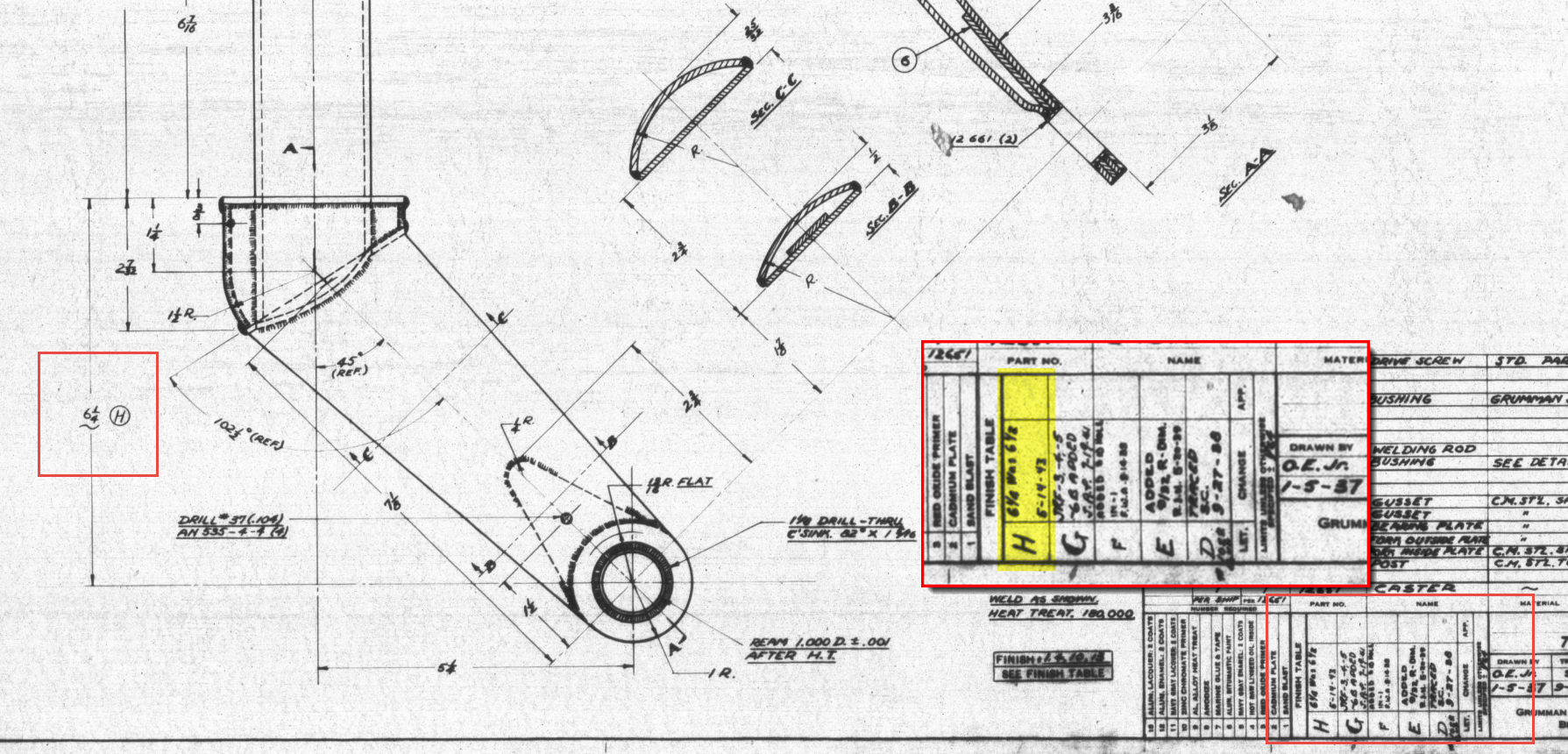
I have intentionally highlighted the revision box to indicate Revision H. This revision specifically documents the change in dimension from 6.5 inches to 6.25 inches. If we examine the other dimensions, the blueprint specifies that the centre axis for the fork should be set at a 45-degree angle. Additionally, the key setting out dimension is 5.25 inches, measured horizontally to the intersection of the vertical axis and the centre of a 1.25-inch radius.
This immediately rings an alarm bell…to achieve a 45 degree fork with the dimensions shown, you would expect that 6.5 inches is in fact correct and that in this case the 6.25 inch is not. But yet it was the only purpose in this revision to record a change to 6.25 inches.
The tilde “~” indicates that this dimension is approximate, but for this to be a revision would suggest that the actual dimension is closer to 6.25 inches than it is to 6.5 inches.
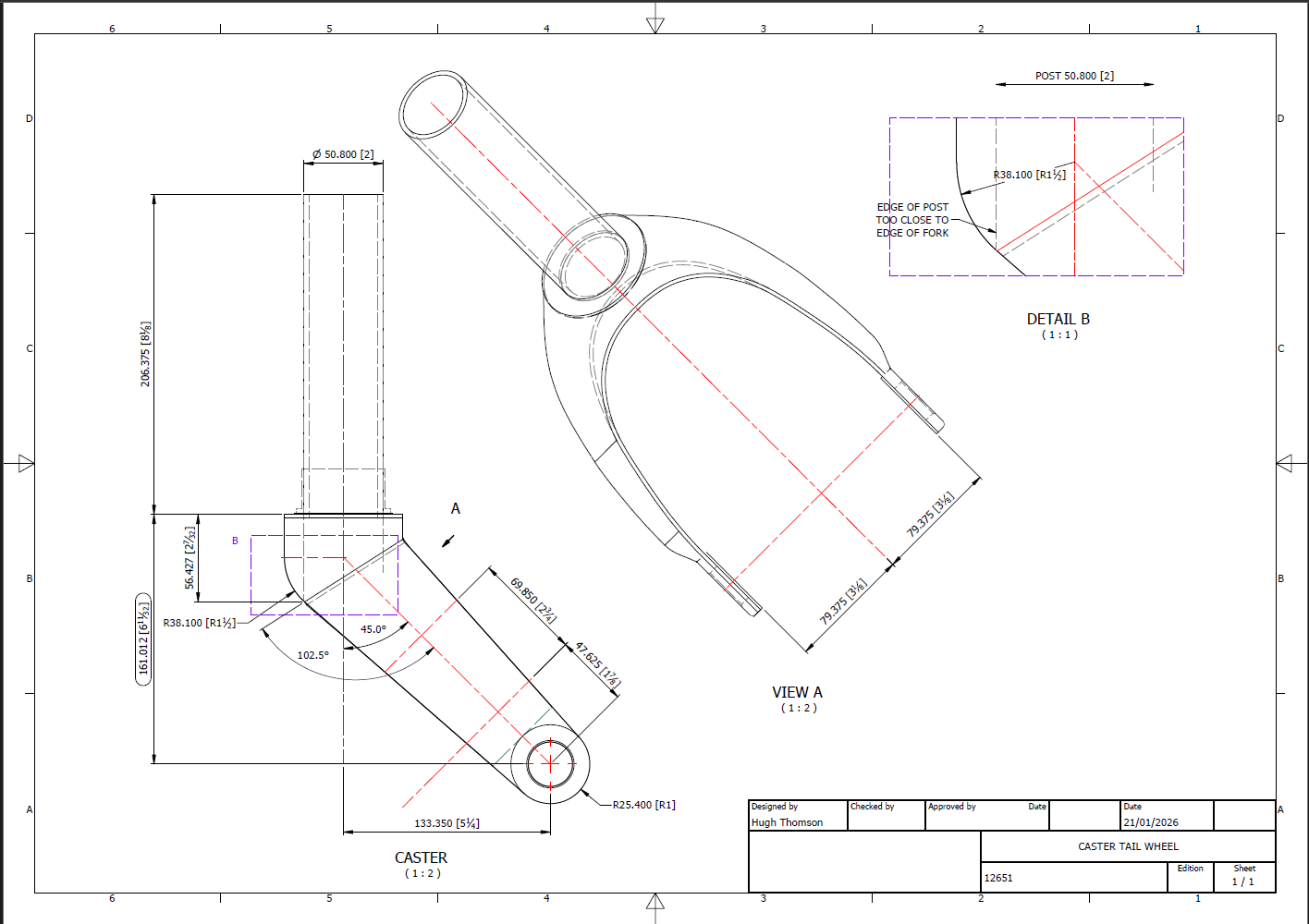
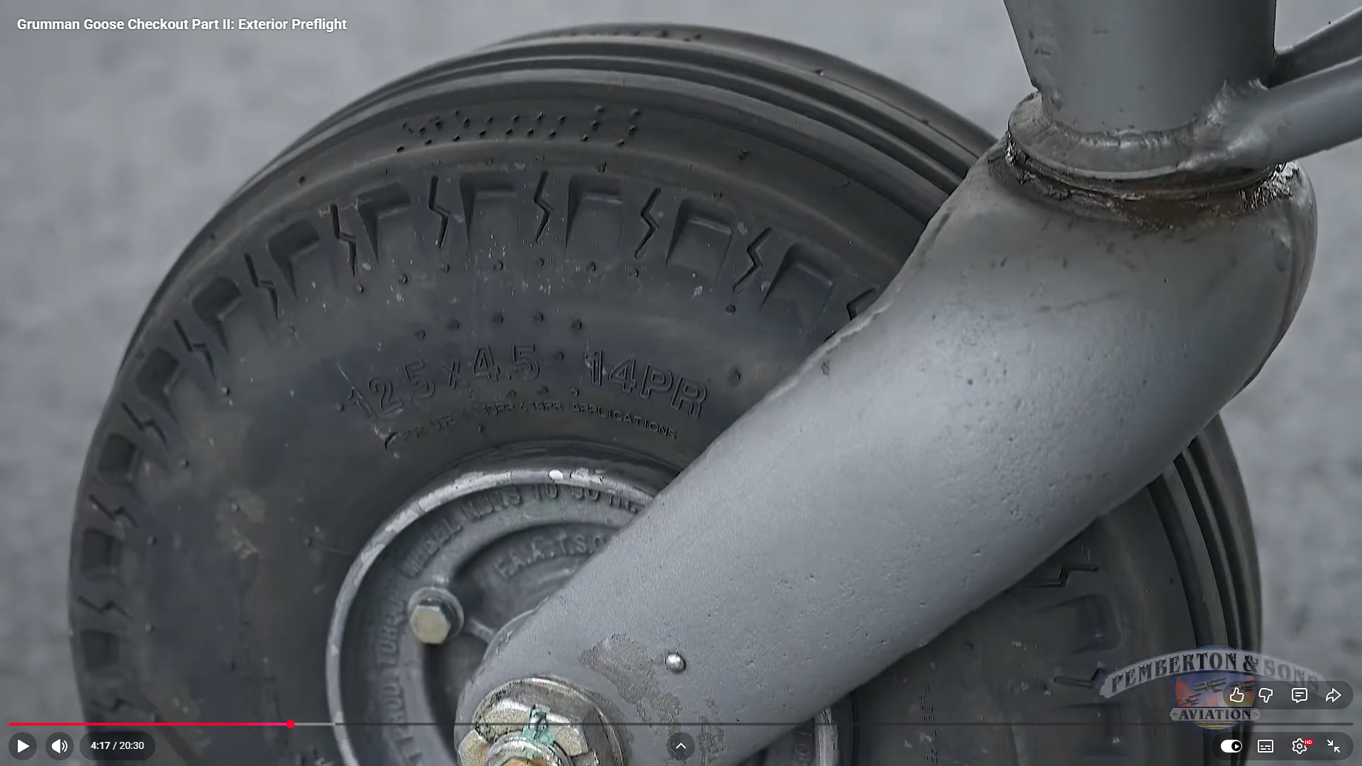
To ensure all key dimensions align with the blueprint, particularly noting that the 6.25-inch measurement is approximate, the setout for the Tailwheel Fork should follow the above depiction. However, we now have a concern: the vertical post is meant to extend to the diagonal intersection and be welded to the curved plate’s interior. As shown in Detail B, the edge of the posts is too close to the fork’s edge, while the blueprint indicates they should be positioned further inward. Additionally, the actual component, seen in the following screenshot, reveals that the heel of the fork is more bulbous than the blueprints suggest.
There was a reason for the 6.25-inch revision, though we do not know it at this time. Therefore, in order for this to be correct and meet all criteria, something other than the 6.25-inch dimension should change.
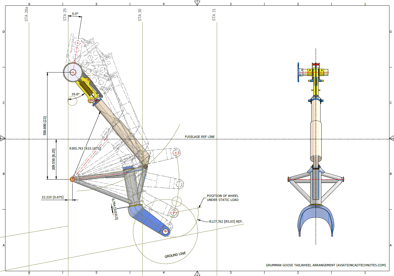
Honestly, I’m not sure what the correct answer is here. Unless I can physically get my hands on the real thing, this will likely remain a conundrum. I will retain the CAD design as it is for now, which serves my intended purpose to demonstrate the deployment parameters of the Tail Wheel and provide clarity on the assembly configuration.
I recognize that the dimensions in most blueprints are generally accurate, with only a few exceptions. When budgets and schedules are tight, it may not be practical to explore entire assemblies in CAD before fabrication. However, in cases where discrepancies are identified, I recommend examining all relevant assembly components in CAD. This will help in identifying the correct solution and understanding all influencing factors before making any changes.
Grumman Goose Project Updates:
I am currently working on a series of updates to the Grumman Goose project. This will include full surface modelling and comprehensive assemblies for the Landing Gear and Engine Nacelle.
The surface panelling is being implemented in a series of carefully planned stages to effectively accommodate the significant variations in surface contours that occur along its length. To achieve optimal curvature continuity for the surface panels, I have undertaken the modelling of multiple fairing contours, each meticulously designed to ensure a seamless integration with the underlying structure. This approach not only enhances the aesthetic appeal but also ensures structural integrity, as it allows for precise adjustments that align with the dynamic shifts in the surface geometry.
The Landing Gear will be fully modelled, including detailed working mechanisms that will later be the driving parameters for a deployment simulation.
I am currently exploring various options for replicating the components as high-quality 3D prints. This initiative is part of a future project aimed at demonstrating operational criteria in a tangible, physical form. I plan to utilise advanced 3D printing techniques and materials to ensure accuracy and durability in the prototypes. Additionally, I will conduct thorough testing to assess their functionality and performance. This approach will not only enhance the visual presentation but also provide a practical, hands-on experience.
As a basic test to check the viability of the project, I 3D printed the front cover of the secondary gearbox to see how it worked out.
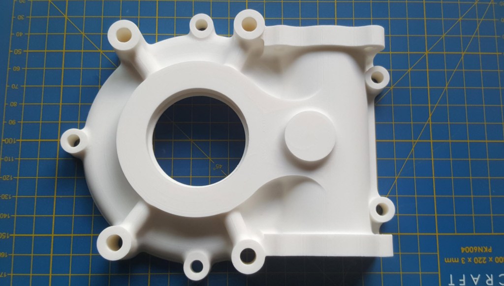
Part #9632 front cover. Printed on an Elegoo Centauri with 0.12 layer height using PLA+ filament. The surface was surprisingly smooth with good dimensional accuracy. Eventually, I will print all the internal gears and check operational criteria.
The engine nacelle is still very much a work in progress, which I will feature in a future post. Following the example of the SU-31 project, the Grumman Goose will also be available in a 1/16 scale version suitable for RC projects.
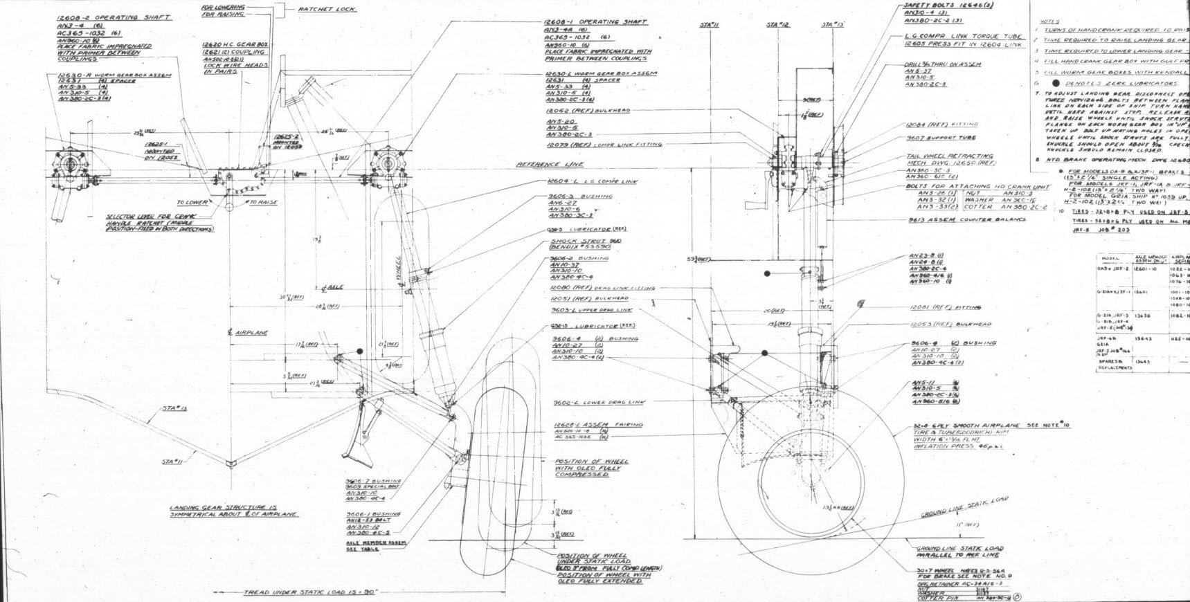
For reference, this is the Landing Gear Assembly Drawing #12600.
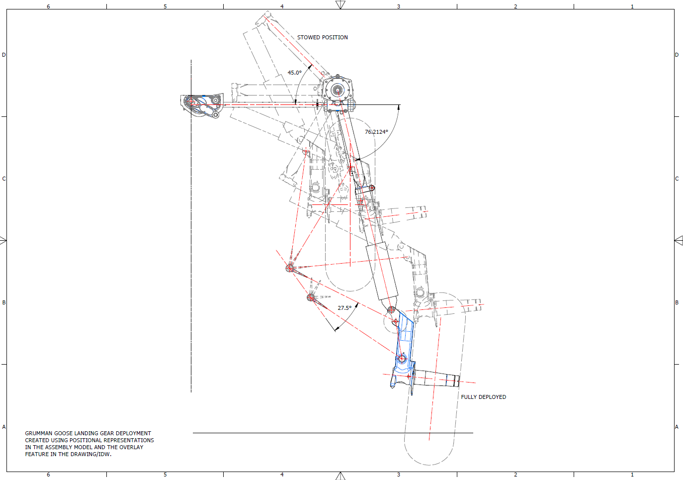
Landing Gear Deployment Positional Representations:
This drawing, created in Inventor, utilises positional representations in the assembly to illustrate the Landing Gear deployment.
RC Project 3D Print: Phase 2
As I embark on Phase 2 of the 1/16th scale SU-31 RC project, my focus will shift to the critical task of selecting the appropriate RC components. I have diligently begun to explore a range of suitable options, taking into account various constraints, including the limited available space and the essential calculations required for sustainable flight.
This marks my first experience using a program called Ecalc, which offers a comprehensive overview of comparable components and their specifications. I know that many of my blog readers possess a wealth of knowledge in the intricate art and science of designing RC aircraft. Therefore, I warmly welcome your insights and expertise to help refine my component selection and ensure that every aspect of the project remains within optimal parameters.
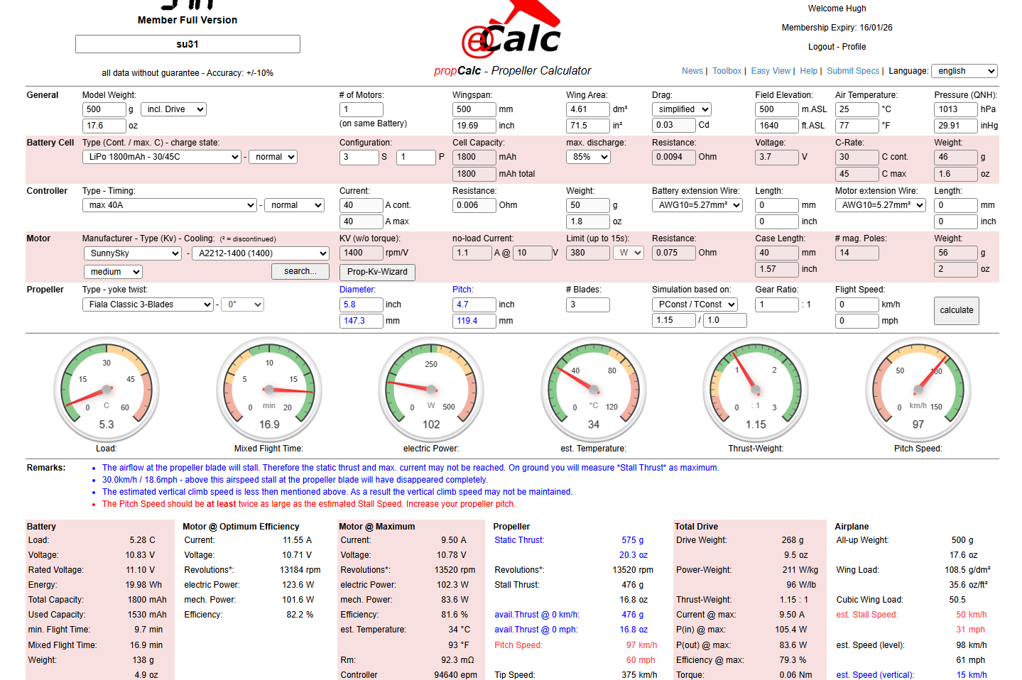
(Image updated 18/12/2025…value of dm2 changed from 4.04 to 4.61.)
Some observations:
Overall, the design appears to function well. Your assistance in identifying parameters for reducing the RPM and determining a more appropriate prop size would be greatly appreciated. We also need to address the blue and red comments noted on the Ecalc form.
In addition to the above, I have also been researching suitable Chaservo thin-wing servos for the Ailerons, which I think may be suitable, as shown in the following image.

There are, of course, higher torque options, such as the Hitec HS 7115, which require more power. The Aileron length is almost 3/4 the length of the wing, so it is important to locate the operating mechanism further out on the wing, approximately 1/3 the length of the Aileron.
For the prototype, I am looking to achieve a stable flight for a reasonable duration to test the strength of the aircraft frame. As I mentioned in my previous posts, the wings and fuselage will comprise thin walls with 10% gyroid infill; therefore, it is imperative to ensure this model withstands the rigours of flight and landing. Perhaps later down the road, we will consider improvements for aerobic capabilities, but for now, let’s just get this thing flying.
Please comment below or send me an email at hughtechnotes@gmail.com. Your help would be greatly appreciated.
Update: This is what the 1/16th scale CAD model looks like.

…the images below show the extent of the full-size original model.
Technote: 3D Printing-My Perspective
Recently, I acquired the Elegoo Centauri printer, and I would like to share some details about my experiences using it for aviation projects. When I received this printer, it actually sat in its box for about a week, as I was not quite ready to deal with the vagaries of FDM printing until fate intervened. I was also swamped with updates to the Grumman Goose and FM2 ordinate studies alongside development of the P-47. I didn’t really have much time for anything else.
Then the unexpected happened: my computer suffered a catastrophic hard drive malfunction. I opted to send the hard drive to a specialist company for data recovery; though technically I could have done this myself, the data was too important. So, having time on my hands, I set up the Elegoo Centauri and did some 3D printing.
I have been using resin printers for a few years, but I have never tried FDM printers. I used to believe that resin printing was the ultimate form of 3D printing when it came to dimensional accuracy and surface finishes, which FDM printers couldn’t match. However, I now realise I was mistaken!
This Elegoo Centauri is, quite frankly, a really good printer, a bargain at less than £300.
As I had an old laptop, I was still able to access my email and online accounts, but running any substantial software was out of the question on an antiquated version of Windows. So what I did was send CAD files from my online backup to my son-in-law, and he would slice them for me and send me the G-code for printing. This was sufficient for me to get started and explore the vagaries of FDM printing. Later, of course, when I got my hard drive sorted and my computer back up and running, I was then in a position to address several questions from my first foray, and this is what I will share with you today.
P-39 Airacobra – Planes of Fame:
As many of you know, and as previously covered in various posts on this blog, I have been assisting Planes of Fame with their P-39 restoration project. Where possible, replacement parts are manufactured to the original material specification; however, in some areas, particularly the cockpit control units, it was decided to opt for 3d printing replica parts. This is a static restoration, so this is quite acceptable. Though I often wonder with the plethora of advanced printing materials, whether 3d printing could be an effective replacement for flight-worthy restorations.
One of the first parts I printed when I got my computer back in working order was the Exhaust Stacks. Previously, I have had a post already on this, but the reason why I decided to print this was to explore metallic finishing options and acceptable material thicknesses.

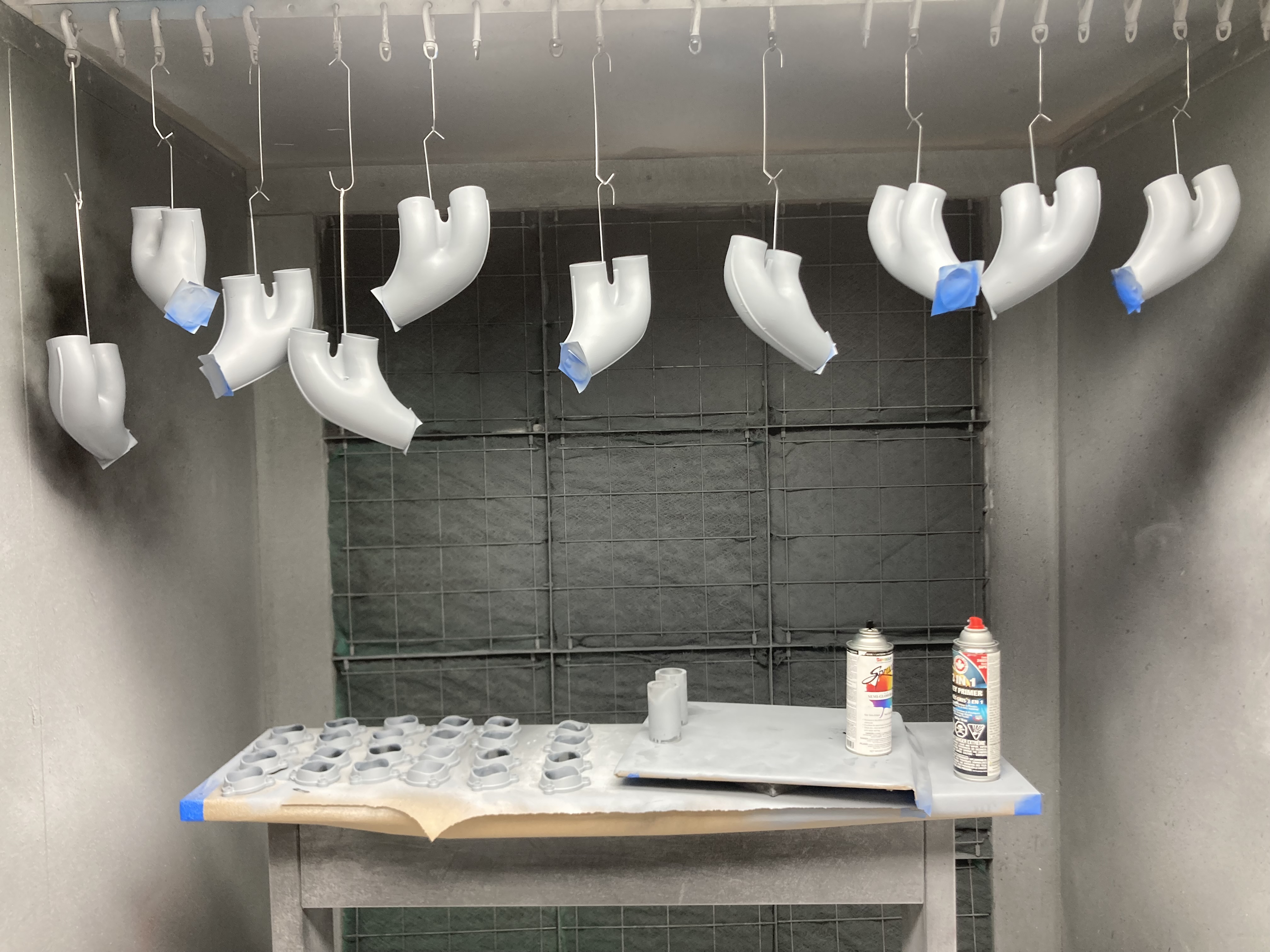
Planes of Fame has access to an industrial-grade 3D printing facility using engineering-grade filament, the results of which are shown in the second image above. I figured that there was no way I could replicate that level of quality on a budget printer, but surprisingly, the Elegoo Centauri did remarkably well just using PLA+.
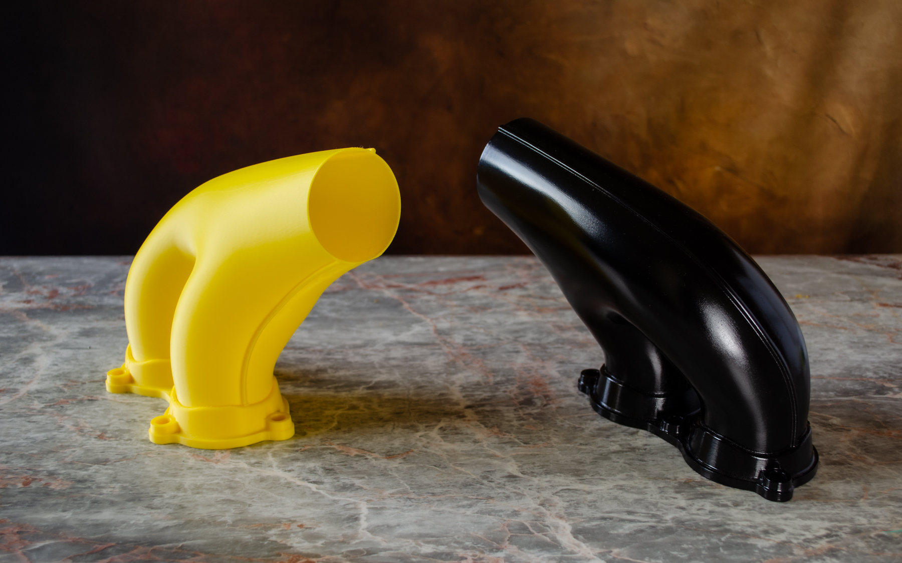

When I developed this CAD model, the exhaust wall thickness was set to 1mm…this was to make it easier for Planes of Fame to adjust the minimum wall thickness to suit the industrial printing preferences. I actually decided to initially print this at the 1mm wall thickness to see how well the Centauri handled thin walls. I was pleasantly surprised that, other than a few minor imperfections, the print came out really well. However, as this exercise was more about exploring metallic finishes, I decided to print it at 1.6mm wall thickness to give me some latitude for sanding. The black version in the first image shows the result of applying Filler Primer; 2 coats of sanding with 80, 120 and 320 grit sandpaper, and then applying 2 coats of black gloss. To achieve the metallic finish shown in the second image, I rubbed in graphite powder. There are several cosplay videos on YouTube showing how this was done on items like the Mandalorian helmet.
The surface should ideally be completed with a clear coat, but I don’t have any of that. The finish, I think, is quite dark and could be improved to be more aluminium-like if the paint were Gloss Grey instead of Gloss Black. I shared these details with Planes of Fame; I understand they may opt for the latter.
Custom Supports:
For the Exhaust stacks, I used the slicer Organic Tree supports, which were fine, but there was some stringing evident on the inside surface. I decided to explore options for custom supports instead to achieve better results. Again, working with a P-39 part, this time the pilot seat top support bracket. I should note that Planes of Fame has this same model; however, they will be making this from aluminium.

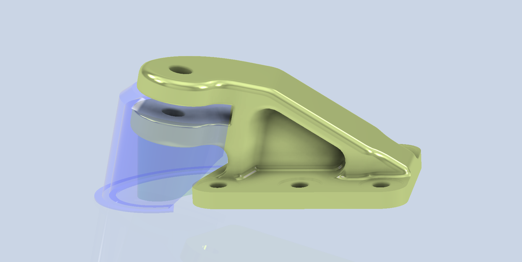
The first image shows the comparison between the slicer standard tree supports and using custom supports. Looking at the circular portion, the item on the left shows an irregular surface from the tree supports, whereas the version on the right shows a much more refined, consistent surface from using custom supports. The second image shows the custom supports created in CAD.
From my experimentation with generating custom supports that a gap of 0.24mm when printing at 0.12mm layer height works quite well. There is some consensus that one layer thickness would be an optimal gap, which may be applicable if the surface is planar to the base; however, in this instance, there is a small incline, and I find that 0.24 works well with the supports easy to remove.
I also did some experimentation with another model, completely unrelated to Aviation, and this was for my wind turbine project.
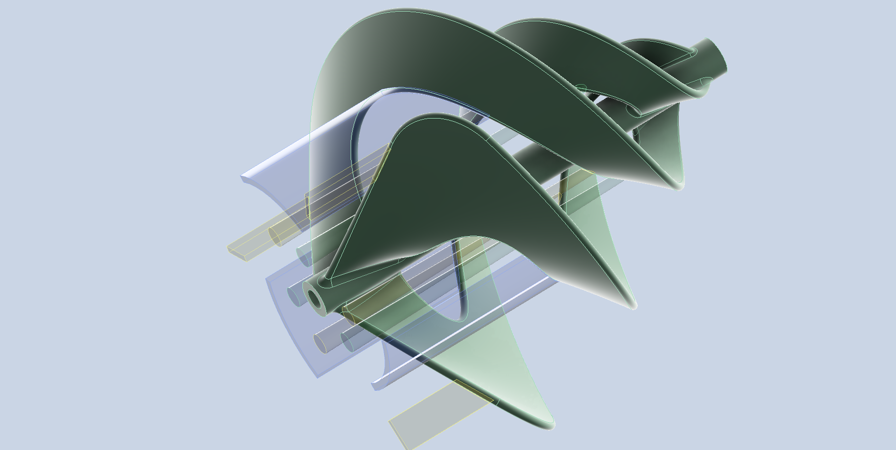

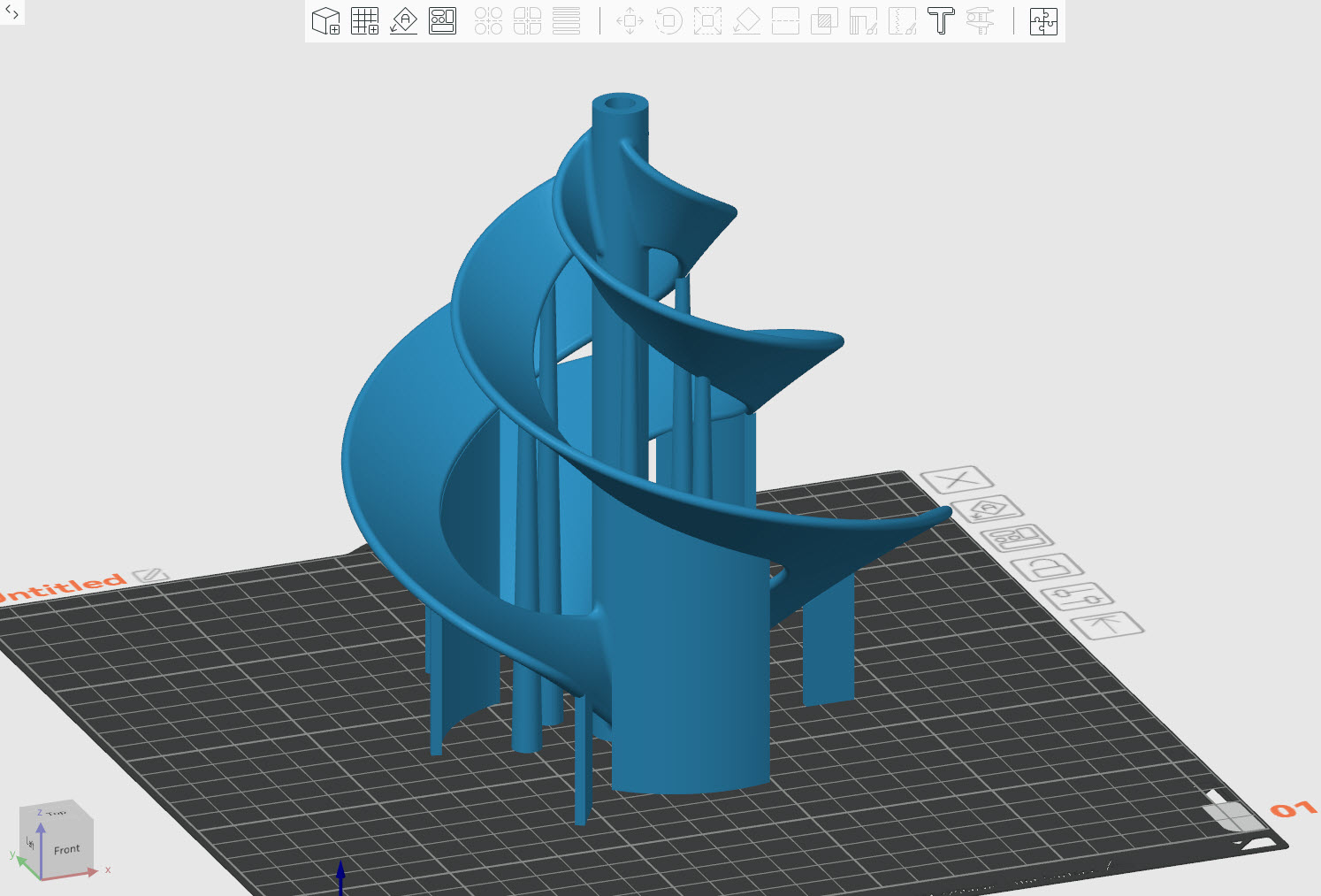
Supports are necessary when the threshold angle is less than 30 degrees. Additionally, I’ve included extra supports to enhance stability, as the model may flex during printing due to the thin blades. I often find that a combination of custom supports and standard tree supports works well on more complex models.
Minimum Wall Thickness:
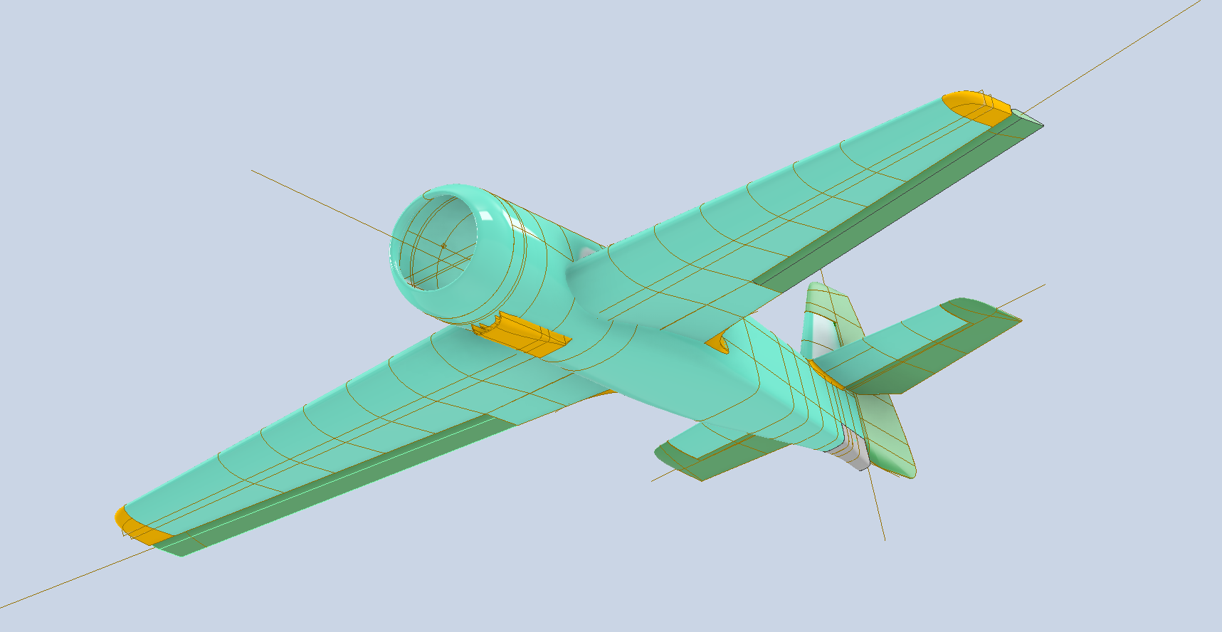
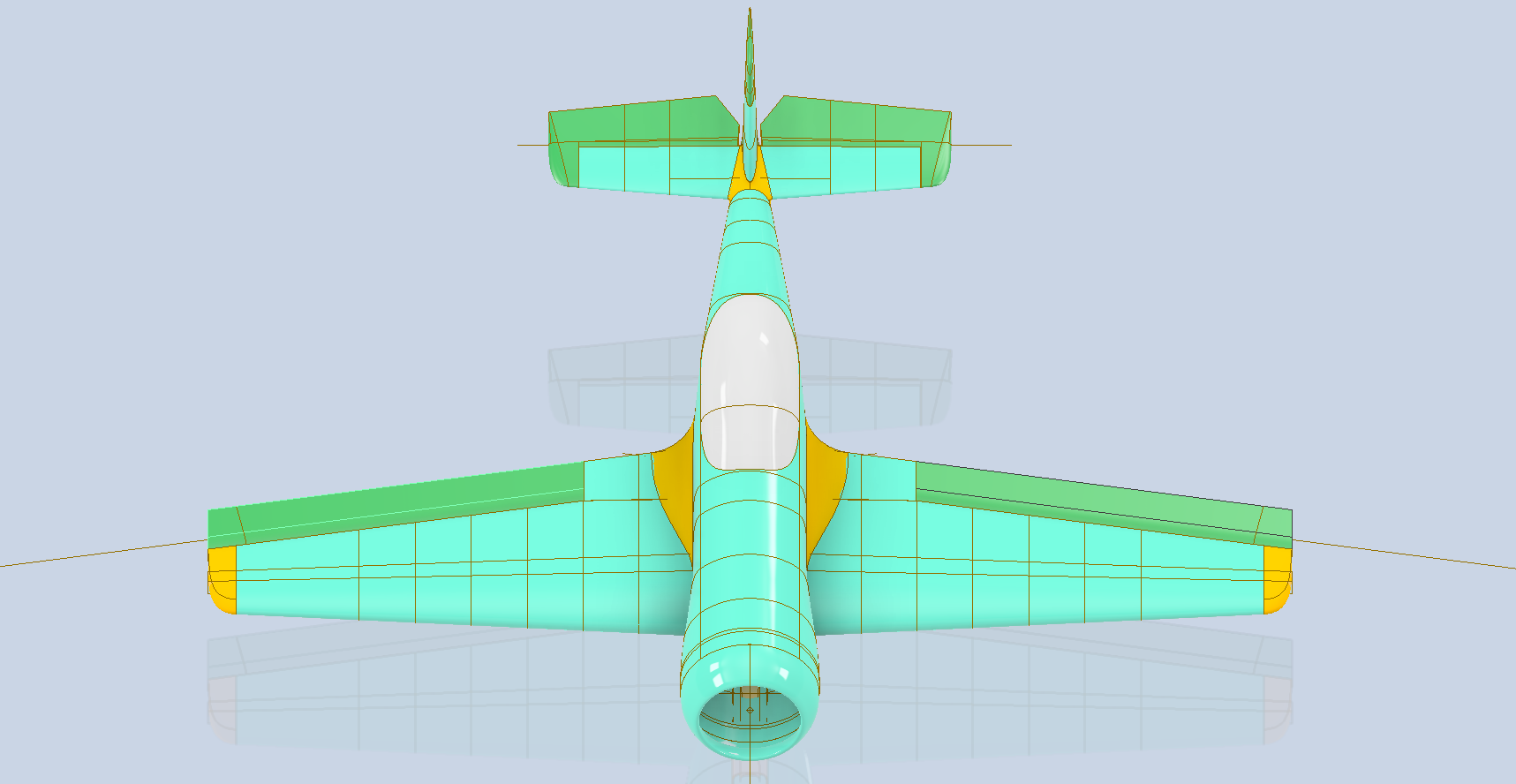
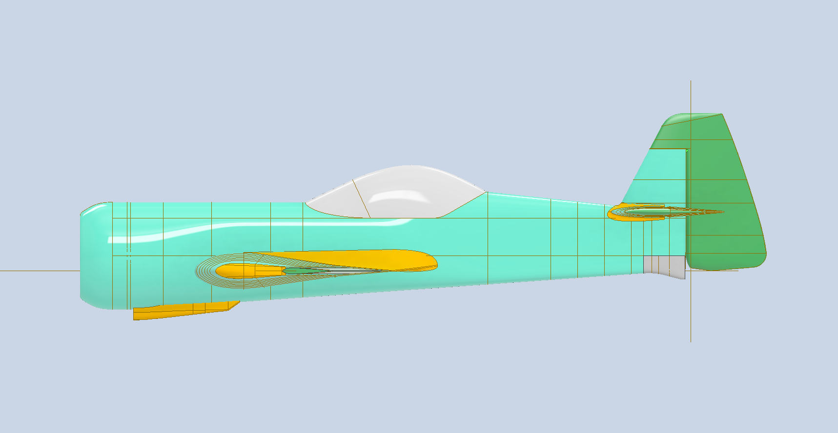
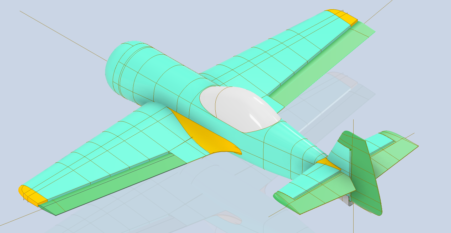
I touched on this with the Exhaust Stacks, and though 1mm is the recommended minimum wall thickness for 3D FDM prints, you can go thinner. There is a setting in most slicers called “Spiral Vase” or similar. What this does is produce a print with a wall thickness equal to the nozzle diameter. I tried this with a surface model for the Vertical Stabiliser for the Grumman Goose at 1:10 scale, and it actually worked quite well.
The downside is that this setting ignores any internal ribs that may be in the model and only prints the outside wall. I imagine there may be some uses for this in aviation modelling, but to be honest, without internal rib supports, there is probably too much flex. I should note that layer adhesion remains good, and the surface finish is smooth.
I intend to explore workable solutions for achieving minimal wall thickness and thus reducing the weight of model RC aircraft. As my main line of work is compiling all the known key dimensional information for the various aircraft and presenting this information in a concise, accessible format and in CAD, I see this as a natural extension of these studies.


I already have several surface models (SU-31 and L23 Blanik) that can be easily scaled and adapted to produce accurate replicas for RC flight. The key to this is when scaling to then apply material thickness to the ribs, frames and surfaces that will be suitable for 3D printing whilst maintaining structural integrity with minimal weight. My current theory is that 2 x nozzle diameter for minimum wall thickness and 3 x minimal layer thickness may work.
My work on this issue is in the very early stages, and I will dedicate a specific post to this with my suggestions and samples of the end product.
Finally: Printing Dowels:
This is something I only ever did on my resin printer due to the possibility of snapping along the layer lines. However, there is a solution for successfully printing dowels on FDM printers. I tend to use dowels a lot for aligning individual parts of an assembly.

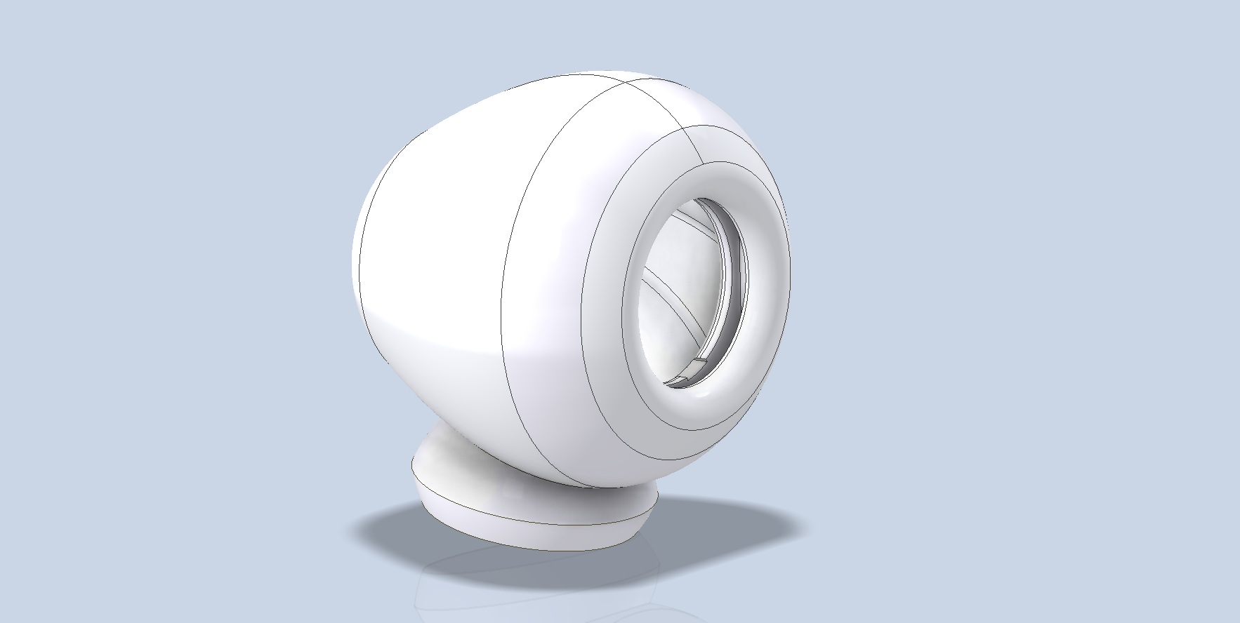
For my desktop speaker projects, the body parts are aligned using dowels. As you can see, the dowel has 3 flat sides which can then be laid flat on an FDM print bed to enable printing with layer lines longitudinal to the axis and thus preventing splitting.
