As I embark on Phase 2 of the 1/16th scale SU-31 RC project, my focus will shift to the critical task of selecting the appropriate RC components. I have diligently begun to explore a range of suitable options, taking into account various constraints, including the limited available space and the essential calculations required for sustainable flight.
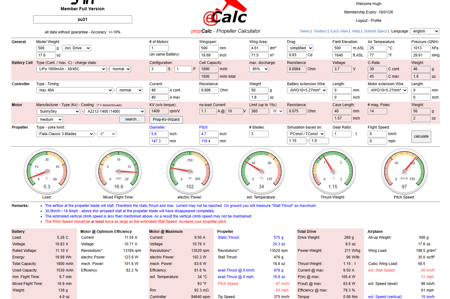
This marks my first experience using a program called Ecalc, which offers a comprehensive overview of comparable components and their specifications. I know that many of my blog readers possess a wealth of knowledge in the intricate art and science of designing RC aircraft. Therefore, I warmly welcome your insights and expertise to help refine my component selection and ensure that every aspect of the project remains within optimal parameters.
(Image updated 18/12/2025…value of dm2 changed from 4.04 to 4.61.)
Some observations:
The overall weight, including RC gear, is estimated at 500g. To be honest, this is a rather conservative estimate.
The propeller size is limited to a maximum of 6 inches; though ideally, I would prefer to get that down to a max of around 5.6 inches, as ground clearance is critical upon landing.
The motor rpm for this size of model is, in my opinion, quite high; my initial attempts at a design with a lower 900Kv were not very successful.
The battery at 1800mAh 3S is fine and aligns with initial expectations and fits the fuselage well. The calcs suggest a minimum of 1600mAh 3S battery.
I am happy with the temperature and Electric Power readings.
Overall, the design appears to function well. Your assistance in identifying parameters for reducing the RPM and determining a more appropriate prop size would be greatly appreciated. We also need to address the blue and red comments noted on the Ecalc form.
In addition to the above, I have also been researching suitable Chaservo thin-wing servos for the Ailerons, which I think may be suitable, as shown in the following image.
There are, of course, higher torque options, such as the Hitec HS 7115, which require more power. The Aileron length is almost 3/4 the length of the wing, so it is important to locate the operating mechanism further out on the wing, approximately 1/3 the length of the Aileron.
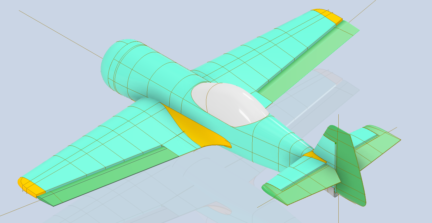
For the prototype, I am looking to achieve a stable flight for a reasonable duration to test the strength of the aircraft frame. As I mentioned in my previous posts, the wings and fuselage will comprise thin walls with 10% gyroid infill; therefore, it is imperative to ensure this model withstands the rigours of flight and landing. Perhaps later down the road, we will consider improvements for aerobic capabilities, but for now, let’s just get this thing flying.
Please comment below or send me an email at hughtechnotes@gmail.com. Your help would be greatly appreciated.
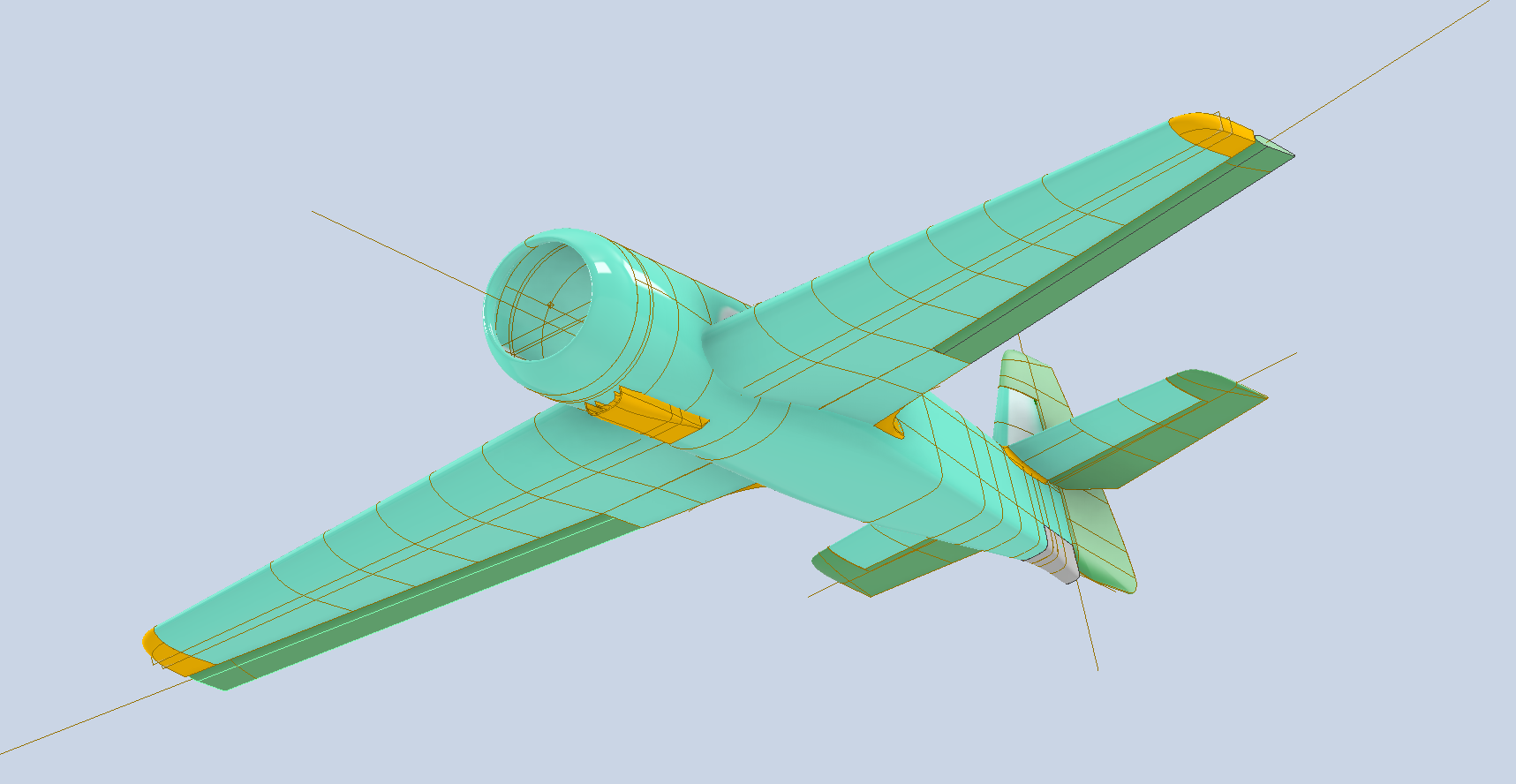
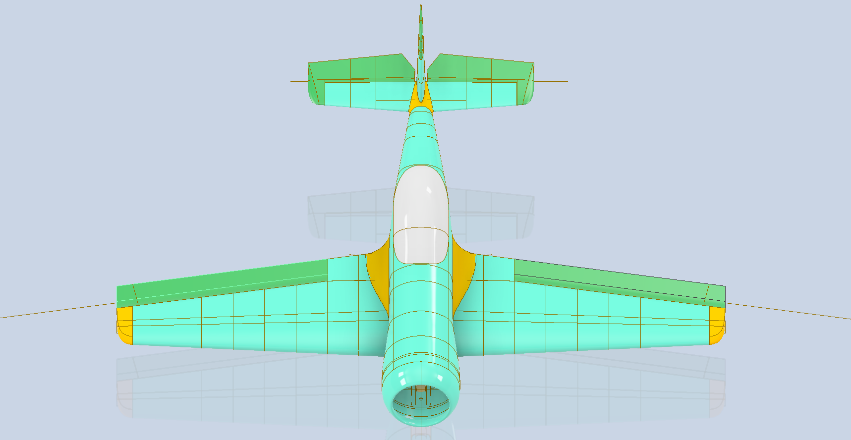
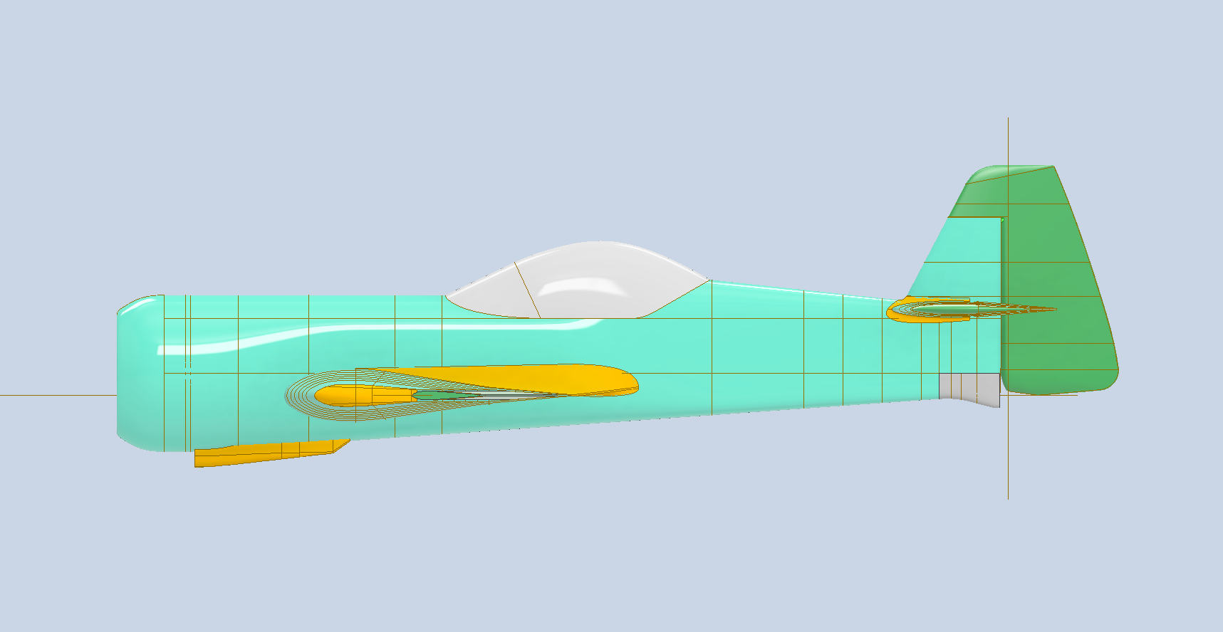
Update: This is what the 1/16th scale CAD model looks like.
…the images below show the extent of the full-size original model.
The JB2 project is progressing quite well, with most of the structural elements in place. I will be doing a lot more detail work on the surface skin and, of course, adding the main support elements for the engine structure. In the interim, I thought it may be prudent to post a few images of the project for your perusal.
Comments or inquiries as usual to hughtechnotes@gmail.com.
Blimey I can’t believe I haven’t posted any updates since April…so I thought I should post an update as a lot is happening. The P-39 Restoration has been a particular focus of attention these last few months, with a particular emphasis on the Cabin rebuild.
P-39 Access Door Sta 86:
P-39N-5 cannon Access Door at Sta 86 positioned between the Rudder Pedal footwells. This took a while to create in CAD due to the complexity of the rudder footwells which are only required for positional reference.
The Footwells do exist which means we have a baseline to check the dimensions in-situ before fabrication. All the original CAD 3D models are provided to the restoration shop along with fully dimensioned 2D drawings.
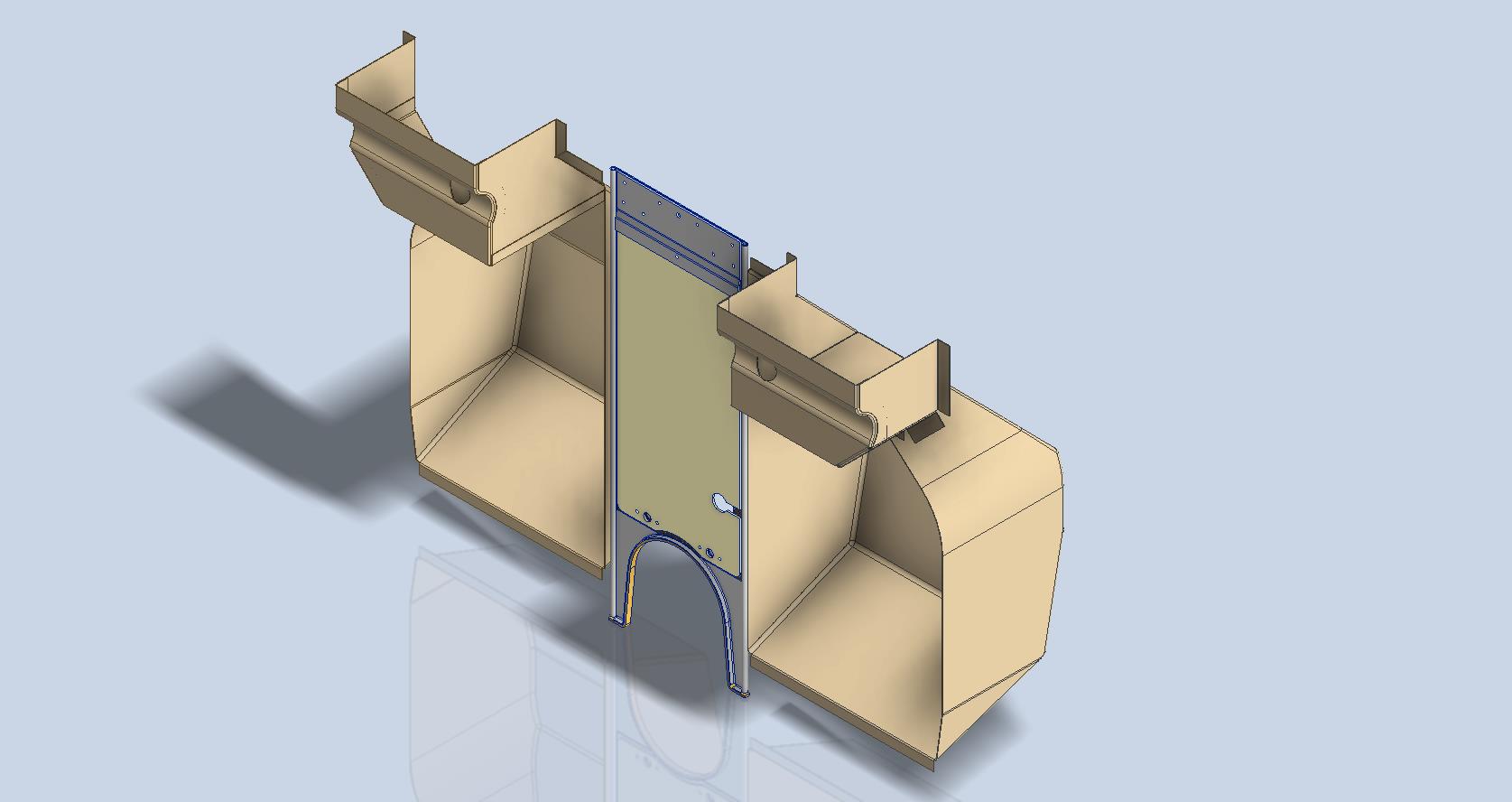
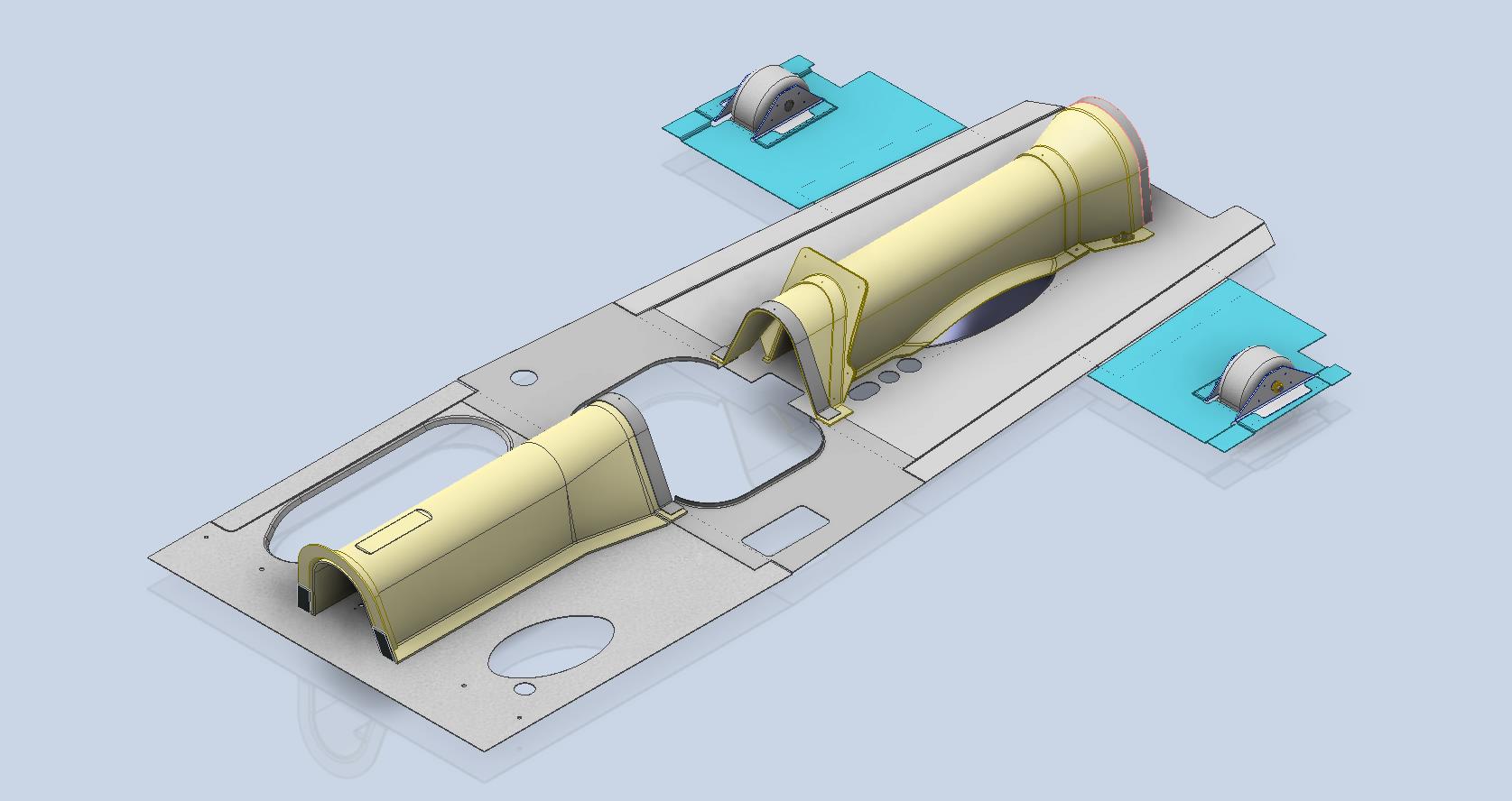
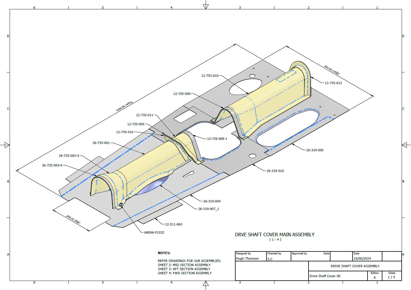
P-39 Drive Shaft Cover:
P-39N-5 Drive Shaft Cover was another interesting assembly because it was decided at the eleventh hour to 3D print the main sections. For this to work the material thickness has to increase to 0.1″ which meant that careful consideration was required to ensure that this change did not impact the interfaces with the existing bulkheads and the Radio Console.
The above images are courtesy of Omnica Corporation.
P-39 Forward Floor panels and Rudder Quadrant Covers.
As you can see the right-hand floor panel is missing and of course the relevant Rudder Quadrant Cover. The left side panel was also created in CAD because there was consideration for replacing the existing panel and Rudder Cover on that side due to the poor condition.
FM2 and P-47:
Moving on from the P-39 the FM2 project is currently on hold as my intent is to visit a few collections in the UK later this year to do further research, particularly the wing geometry. The P-47 has made its very first mention on this blog…another ordinate study for a friend which is progressing reasonably well but with the focus on the P-39 this will take a bit longer than I had planned.
P-51 Mustang:
The P-51 has popped up again after so many years…not an update per se but a new direction for me on the 3D printing side of things. As some of you already know I have been messing around with 3D printing for a while now mainly the SLA resin. Many moons ago I fully modelled in CAD the Tailwheel mechanism, some of which I had already 3D printed. The reason for revisiting this project is to 3D print more of the parts as a test bed for different resins to examine various structural properties, dimensional accuracy and of course, play about with different finishes. Also to determine just how thin I can go with 3D printed parts and still have a workable mechanism.
This P-51 is a side project that will help me devise solutions for the ultimate goal which is to replicate flight instruments and controls.
As you know original instruments for these aircraft can be very expensive and just furnishing a static display restoration project with the original instruments somehow seems a waste when a replica would be sufficient. This way we can make available the original instruments or parts thereof for refurbishing/restoring for an actual flying aircraft restoration.
My budget for this is rather limited for purchasing materials and I also have limitations on the Elegoo Mars Pro print volume. However, I can work within these limitations…it just takes a bit longer! Something like the newer Elegoo Saturn Ultra would be a dream for this sort of stuff…maybe someday!
The resin I’m currently reviewing is the Anycubic ABS-Like washable resin which surprisingly is rather good…now I have the settings dialled in the detail and dimensional accuracy is exceptional. I will endeavour to test some of the engineering resins like the JAMG HE products though they do require a heated VAT. I see a lot of potential for 3D printing parts in the restoration of static aircraft projects. I would suggest organising the CAD workflow so the original parts are modelled to the manufacturer’s exact dimensions and adjustments made only to derived parts thus retaining the original details.
Another aspect of 3D printing worth exploring is for making molds and something else I am keen to try is whether it is strong enough for vacuum-forming thin sheet aluminium.
A lot is going on here at the moment with work continuing on the various aircraft whether that be ordinate studies, designing for manufacture or indeed exploring the vagaries of 3D printing.
12 months ago I started providing CAD design services to Planes of Fame, Chino to assist them with the restoration of a P-39 Airacobra. This aircraft is a static display restoration so we had some latitude in the manufacturing of the various parts. This included 3d printing (which is done by a professional company), sheet metal work, and vacuum forming.
The CAD models generally are for small complex geometry parts as you can see in the examples posted below. When preparing these models everything is double-checked against blueprints and where necessary the aircraft itself to ensure correct profiles.
I have over 40 years of experience in Engineering Design and drafting; in fact, I actually started my career as a draughtsman on the drawing board. I question everything and take nothing for granted with a focus on detail and accuracy. So when I prepare the 3D CAD models I also create a 2D dimension drawing as a checking mechanism to ensure accuracy and also as a reference for the engineers. If the 2D drawing is actually produced specifically for manufacture instead of being a design check it will incorporate all required standards references, tolerances, and material specifications.
3D CAD modeling of parts for aircraft can be quite complex and can take a long time to complete. The smallest part here would normally take about 3 hours. That may seem a lot of time for small parts that appear to be quite straightforward but often it is the reference geometry not visible that takes the time, whether that be the curvature of the wings or fuselage. Then everything is checked and documented.
The P-39 Restoration project still has a long way to go which I feel privileged to be part of.
If you require parts developed in 3D CAD for your project then please don’t hesitate to drop me a line at hughtechnotes@gmail.com.
I would like to take this opportunity to wish everyone a Happy New Year.
Interspersed throughout this blog are many examples of Technotes describing techniques and problem-solving primarily for 3d CAD modeling. Many of the part examples shown are actually created to address another major issue with Assemblies.
It is not uncommon for the assembly drawings to be either unclear or simply void of key information that would help establish relationships between sub-assemblies or parts. In many examples, it is simply that the reproduction of the microfilm prints is not sufficiently clear to comprehend what is going on, otherwise the omission of basic dimensional relationships.
For the P-51 Mustang, I fully developed the rear Landing Gear mechanisms to clarify what the heck was going on as the NAA Assembly drawings details were obscured.
It is too often the case that general assembly drawings tend to be nothing more than an illustrated parts list with few key dimensions that define locations or relationships between the individual parts. This is also true for many of the sub-assemblies. For the P-51 Tailwheel sub-assemblies, I also developed 2D detail drawings showing key dimensions and parts lists. Ideally, I would have developed presentation drawings showing the exploded views of each of these assemblies to provide further clarification…perhaps a project for the future.
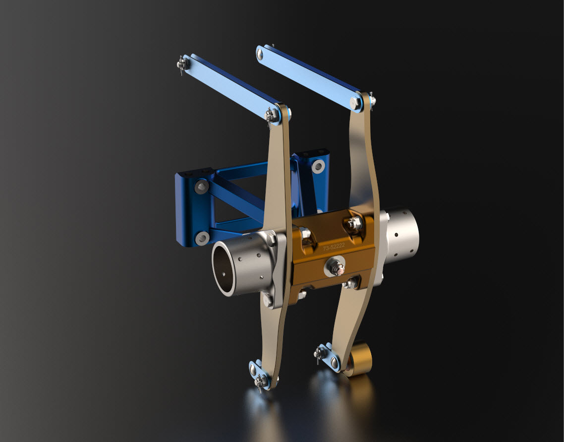
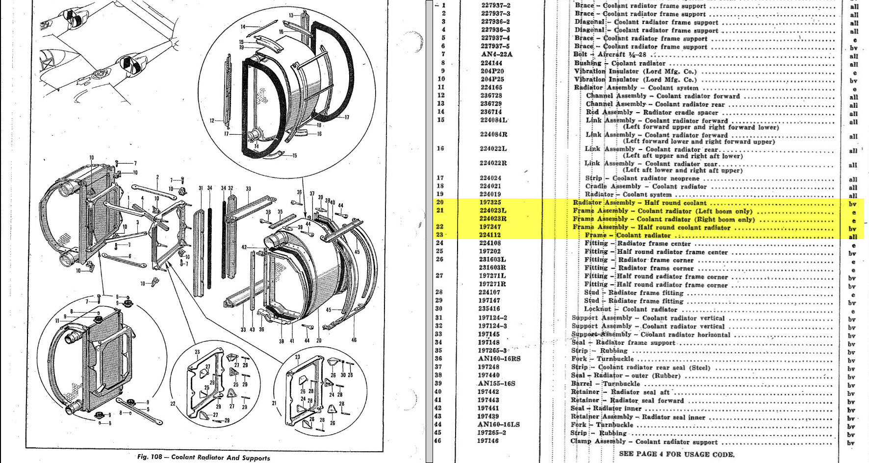
In the case of the P-38 Lightning, I have developed the Landing Gear assemblies to check the ordinate dimensions… which by the way are good. I now have the Coolant Radiator assembly which was again developed to check ordinate data but also for the same reasons as I did the models for the P-51 Tailwheel.
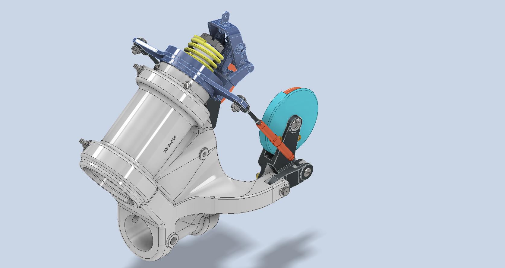
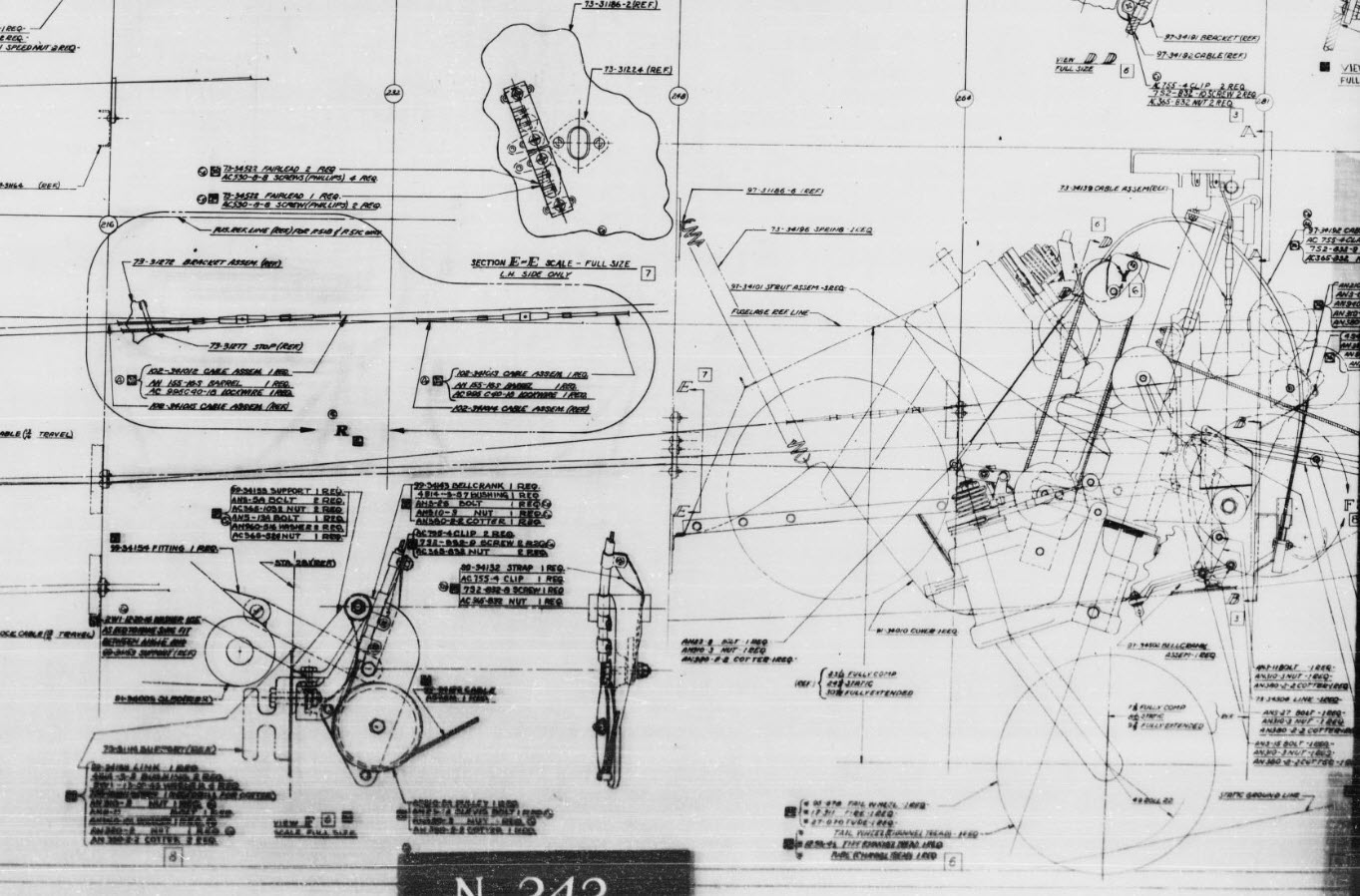
Typically the general assembly pictorially shows the sub-assemblies without any key dimensional information to define the location or part relationships and similarly, the sub-assembly for the clamp is not that much better. This is important stuff as occasionally they are the only reference material we have to help define ordinate data that is missing from the archive blueprints.
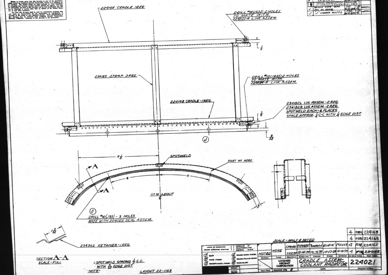
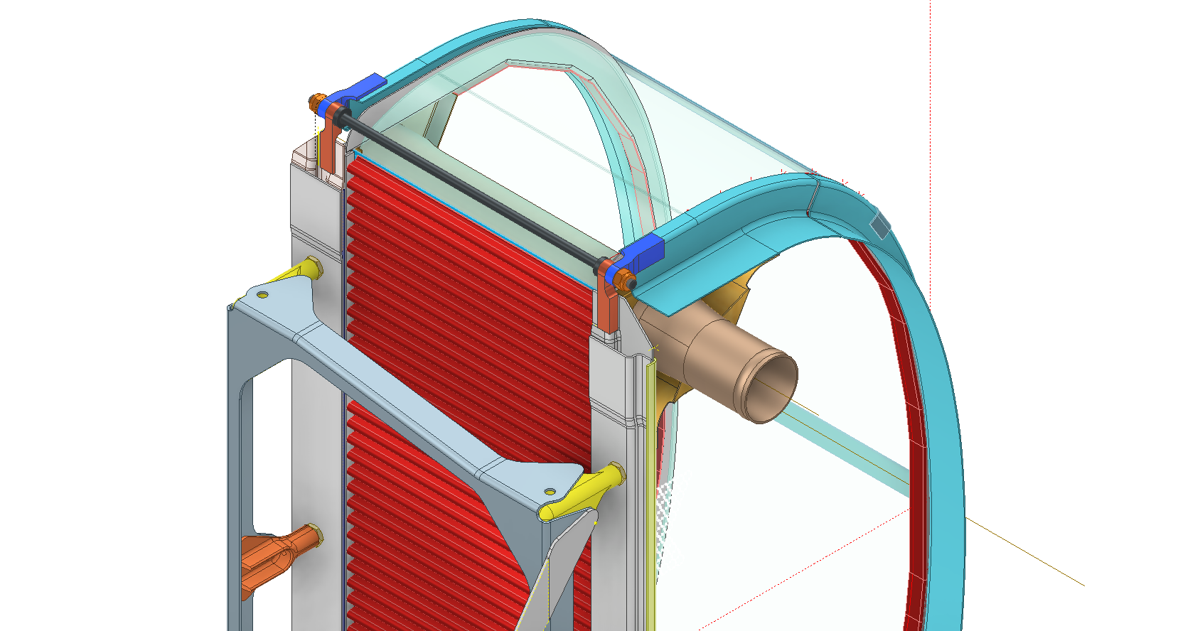
The Coolant Radiator is compromised by wrong dimensions as well…the top clamp cover, for example, had dimensions for the connection to the rod with the part drawing showing conflicting locations for different views of the same part.
The problem here is the connecting bracket item 224045 cannot possibly be 1″ from the edge of the cover plate whilst the overall dimension of 6 7/16″ prevails. I initially had located that bracket at 1 inch which seemed to be correct at the time because it fitted the part profile but when I introduced this into the assembly drawing it would not correctly align with the radiator. However, when I revised this using the 6 7/16 inch dimension it worked. That connecting part also caused more problems because the face of the part is machined 1/64″ which is not taken into account when positioning the part in the assembly.
Accumulatively this resulted in the overall width of the clamp assembly being smaller than it should be. This only came to light when I modeled the 234183 almost inconspicuous part as the stated dimension of 9.25″ did not fit with my initial layout..my first thought was this may just be an oversight but when I tried to align the main support frame (in gray) it did not align correctly. I went through everything and realized that the machined face of the corner parts connecting to the rod as shown may not have been taken into account and when removed the alignment was better and the 9.25-inch dimension on the strap was now correct. I am convinced that there should be spacers/washers between those connecting parts but this is not apparent on the assembly drawings. There remains a small discrepancy of 0.8mm which I am unable to account for….as this mainly relates to a clamp mechanism that will be compressed on assembly it was probably not deemed important but when you are trying to establish baseline dimensions it is actually very important.
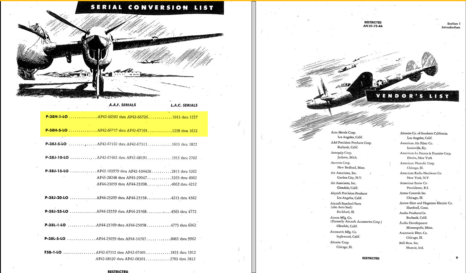
The Part catalogs generally are your first port of call when developing these assemblies but they do not contain the key dimensions you need so these 3d CAD models are essential to achieve clarity. Incidentally, while we are talking about part catalogs it is important to understand what parts belong to which version of the aircraft. For the P-38 Lightning, the first few pages list the version and serial numbers which in turn are listed elsewhere where a Usage code is assigned. In this case the “e” is essentially the P-38H and the “bv” is the P-38J. The P-38 Part catalogs tend to show the version variations on one page; which can be really daunting; whereas others may show the version differences on separate pages…so you have to be attentive.
As I mentioned at the beginning of this article the main purpose of these assembly models is to achieve clarity and to check dimensional relationships. I think this is very important stuff that would certainly benefit from exploded views in conjunction with clear assembly 2d drawings.
As usual, get in touch if you can help support my work. hughtechnotes@gmail.com
An update on some recent work I have done for the P-38 Lightning and P-39 Airacobra. For the P38 Lightning, I now have the Boom Tailend interface with the Empennage and for the P-39 Airacobra, the new work includes the Auxiliary Fuel tank, Wing and underside panels at the Centre Section.
P-39 Airacobra Wing Layout and Aux Tank:
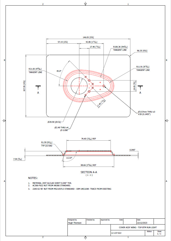
I was doing some research into the various closed penetrations on the underside panel as shown in the photograph on the right. So I modeled this panel to get a clearer idea of what was happening in this area as marked “A” in the underside view and front view images above. The 2 oblong holes are actually openings that normally would have a curved reinforcement which I understand would be used for the Auxiliary Fuel tank pipes and hoses. The Teardrops are for domed covers, which you can see more clearly in the first image view.
The Square cutout towards the rear of the panel is for the exhaust Flap and the slot to the front is for a removable panel that houses the Auxiliary Fuel tank mounting. The Aux fuel tank itself was well documented and was an interesting model to develop…I still have the fuel cap and vent pipe to add along with a few bracing struts to complete.
Following this exercise, I decided to further develop the wing layout. Although the CAD work for the wing was well-dimensioned with outlines for the Wing plan, Front Beam, Rear Beam, and Aux Rear Beam there was not much information on the actual rib profiles. We know that at STA 1 (22″) from the center of the ship the rib profile is a NACA 0015 and at the wing tip this is a NACA 23009 profile (204″ outboard). Other than that we have virtually no ordinate information for the ribs except for a partial profile at STA 7 +7.
The arrangement for the wing has been a subject of debate on several forums mainly regarding the construction of the Wing Tip. Usually, when there is a change in the rib profile the change occurs at the intersection of the wing tip and main wing however in this instance it is located at the extreme point of the wing tip. So the surface model is based on a loft between the 0015 profile at the root and the proxy 23009 profile at the extremities. This loft reveals an interesting caveat related to the evident wing twist and alignment of the Leading Edge.
Clarification on the location of the different NACA profiles was actually found in the NACA Report L-602 on the Flying Quality of the P-39 which defines the relative positions of the profiles. The caveat I was talking about relates to the wing twist…normally when we think of Wing twist or Washout we visualize the rib rotated about the 30% or 35% chord with the leading edge dropping and the trailing edge lifting slightly…but that is not what is happening here. The entire 23009 rib drops from a static position at the trailing edge towards the leading edge…the rotation is roughly 1.257 degrees. This results in a continuous leading edge downward alignment all along the length of the wing from the root to the tip.
As this is most unusual I was able to check the resulting surface model against known dimensional information for the beams and the partial profile at STA 7 +7 which matches. I still have to model the wing tip which has an interesting upward curvature.
P-38 Lightning Boom Tail End:
Another challenging aspect of the P-38 Lightning was determining the geometry for the Boom Tailend…essentially the intersection of the Boom and Empennage. We do have the lines of intersection for the Vertical Stabiliser, Horizontal Stabiliser, and the end of the boom but we don’t have any dimensional information for the curved profiles though we do have drawings that give us some idea of the profiles.
This was surprisingly difficult to get right and to be honest this final version is the result of 3 different attempts to achieve a viable solution. At first, I attempted to draw the Boom section, and stabilizers then fill the void with a surface patch to naturally define the curved fillets…with a few guidelines I managed to get a reasonable result but I incurred a few anomalies with the finished surface which I couldn’t correct. The second effort was more structured with a number of contours traced from the available drawings as a reference to gauge the curvature and then try again with surface patches but this time is broken down into quadrants, top 2 sections, and bottom sections…this was better and very close but again I had a few surface deviations at the leading edges.
Finally, I decided to have a look at using variable radius fillets…although I had already tried this unsuccessfully I changed my approach slightly which gave me good results. The fillets I used initially were tangential which caused a few problems where they met particularly on the top surface…what was happening was a sharp edge developing where the fillets intersected…so that was no good. It also mattered in which order the fillets were generated.
Eventually, I figured why not try G2 fillets and see if that worked…I am always wary of using G2 fillets due to some bad experiences using them before but I was running out of ideas and I was keen to find a workable solution. I started with variable G2 fillets at “1” and “2” with several control points to control the curvature and avoid folding the surface at the leading edges. After some fine-tuning, this worked out well for the first 3 locations. The remaining fillet for the Vertical Stabiliser did not go quite so well as it was impossible for the CAD software to give me a G2 variable fillet…so this one ended up being tangential. Perhaps with a bit more tweaking, it may have achieved a G2 fillet but I had spent many hours on this and I needed to make a decision.
There is a very very slight edging but it is almost unnoticeable on the final product. The final curvature of this model matches well with the guidelines extrapolated from the drawings and I am satisfied it is a very good representation of the Boom Tail End.
I hope you find this article useful and as usual any inquiries please get in touch at hughtechnotes@gmail.com
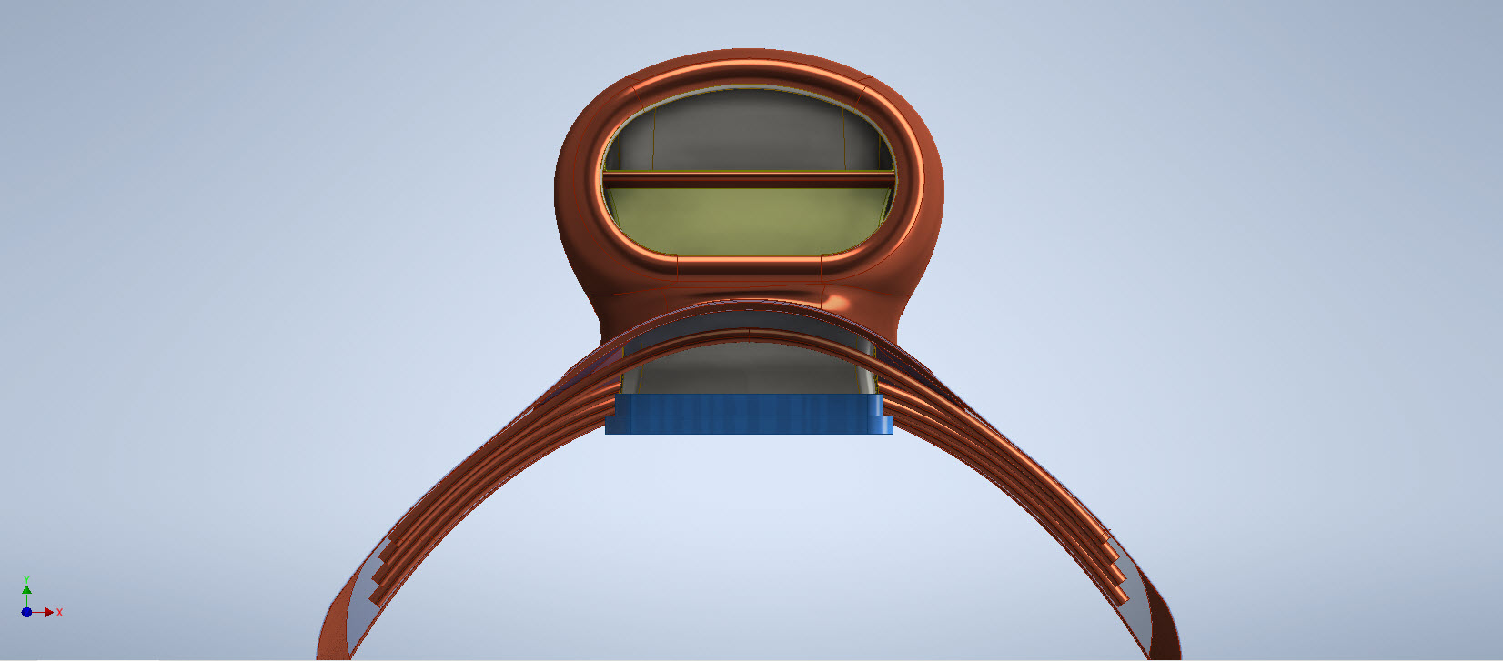
This rather small unassuming item is at first glance a straightforward little model that actually turned out to be a huge headache. I spent several days working on this model which will all be explained in this article. Hopefully, the solutions I found can help you.
The first hurdle was the Bell Drawing 12-614-001… several key dimensions were illegible and a complete end section was non-existent. The first task was to develop what I do know to help determine what I needed to know…that in itself took an inordinate amount of time but eventually managed to get that sorted. In addition to the sections shown on the drawing I needed to include a control sketch to control the dimensions of the eventual loft activity…this was essentially an ellipse with fixed height and variable half-width.
The side/outside lines of the Exhaust Stack are fixed profiles so it will be the inner profile that will change to make sure that the intersections of the 2 pipe exhausts were correctly located in the centre of the element.
You will notice the side profile sketch is separate from the main model sketches, this just makes it easier to see what I am doing as for the most part, it was mainly for reference.
At this stage, everything is quite straightforward as all I had to was loft the 2 pipes by selecting each of the profiles as shown and then trim the surfaces to give me a base model. A small tip: for this to work correctly and ensure the alignment with the external lines and allow for expansion internally it was necessary to loft using the Centreline option…the centerline holds the loft shape between sections normal to the centerline.
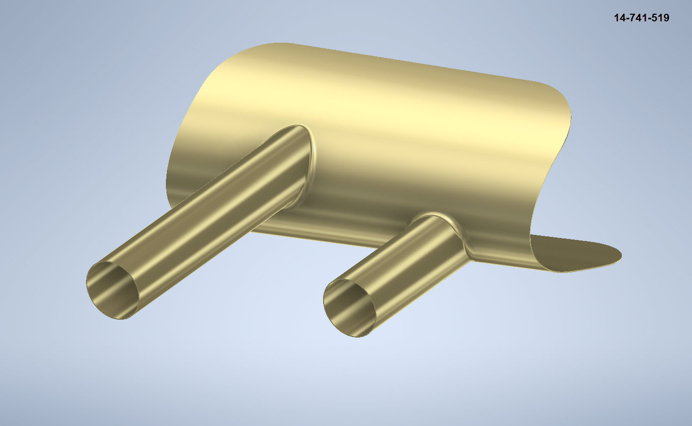
This is where everything got crazy. The main body part of this stack has no joint seam and is quite bulbous…so what I had to do was adapt this base model to form the bulbous surface complete with an internal curve.
As you can see in the image on the right the real item shows the bulbous main body part and the generous inside curve. By the way, some may have observed the real item looks shorter than the model…this is a puzzle…some of these exhaust items are indeed short and this is further noted on the Bell drawing as a dotted line! I suspect this may be linked to the engine used but as yet I do not know for sure.
I initially created the short version thinking that this was normal until I found out that most are actually longer versions. That was the start of many frustrations to come as that first batch of models was quickly scrapped and started again. That bulbous bit though is the main problem.
In order to achieve this I had to derive a solution that filled the void between the 2 tube lofts and at the same time provide an internal curve consistent with the real product. What I opted to do was simply trim and then remove the inner surfaces and then blend the remaining void with a surface patch.
My initial effort was to remove the centre section according to the natural divisions along the centre of each tube and the sketch plane. I tried variation after variation on this, adjusting tangency strength and G2 for each side, I even adjusted the dimensions on the control systems to make minor corrections. I eventually ended up with something reasonable and we got it 3d printed. The second image above is the latest model incarnation which I will explain below.
Two immediate issues are quite visible on these printed models…the initial curve between the 2 tubes is far too tight and almost looks as though it has folded. The second is the surface continuity…okay admittedly I was unsure about the short and long versions of this stack so the end extensions were a separate model part…though I should note that the surface should have been tangential and it’s clearly not.
Coming back to the cad model above…the second image shows what needed to be done. In this one you can see the cutout in the main body is an ellipse which gave much better results and a larger smoother curve between the tubes.
What was happening with effort 1 was that choosing the centre of the tubes at 2 and 3 (which by way was a logical choice) was actually restricting the area in which the inner curve could form, resulting in small deviations in surface accounting for the folded look. Essentially by selecting the centre lines I was actually creating self-imposed restrictions. It took me a while to figure that one out and many hours of work.
Further the mere fact that this patch includes sharp angular corners also did not help as the patch stretches to accommodate those corners again leading to imperfections. Finally, I decided to forego that first attempt and ended up using an ellipse profile that extended beyond the centrelines of the tubes. As there were no sharp edges continuity of the surface patch outline was good and ended with a smoother patch surface that was G2 compliant. There is a small additional patch at the end of the stack…there was a natural seam there which I needed to get rid of.
The final model is shown above and is a very much improved surface with good continuity and a generous internal curvature between the tubes. One final point is the mounting plate… which is not dimensioned on this Bell drawings because it is a contractor-supplied item. I searched through many drawings and found something similar…so I cannibalised the dimensions from that drawing to create the mounting plate. It turns out that this was a good effort as it actually aligns with the engine block.
Surface modelling is rarely this complex but occasionally you will come across something equally challenging. If something is not turning out the way you had hoped or expected just check to see if your choices are imposing restrictions on how the surface is created. When you are trimming or splitting surfaces try to minimise sharp edges and instead opt for curved circular solutions.
Update: 7th October 2022:
Just received word that the newly revised Exhaust Stack model has now been 3d printed…just another 11 sets to go. Apparently, the time for printing and ultrasonic cleaning will be about 4.6 days. They look good…check out the awesome curvature on these prints.
Following a recent inquiry about the P-39 Airacobra, I was asked if I had a model for the P-39 Carburettor Air Scoop. At the time I didn’t, though I did have some preliminary outlines that were done as part of the dimensional ordinate study. So I decided to get stuck in on this new project and see what can be accomplished…by the way did I mention this will be used on a real aircraft. The template moulds will be 3d printed and used to form the aluminium plates.
When you look at a photograph of the Carb Scoop it looks deceivingly uncomplicated however it turns out this part is surprisingly complex. The main body part itself is challenging with the curved profiles and filleted interfaces, the curvature of the fuselage; which by the way is not actually documented anywhere and the transitions from one frame to another to achieve smooth curvature. The internal duct comprises many varying profiles…the profiles tend to be rectangular with different corner radii throughout culminating in what can be described as a slot profile for the Air Scoop inlet.
I have been working on this for a few days now studying various modelling methods to achieve the most accurate and consistent results. So far I have the main scoop body and the fuselage skin modelled. The internal ductwork is set out on a sketch, though I will still have to define a number of intermittent profiles to ensure I get that right as well. Overall there are 12 individual parts for this assembly all detailed on one drawing…so some interpolation of design intent and cross-referencing with a few external drawings is essential.
At the Scoop inlet, there is a small lip that I have yet to model. The drawing has very little information on this so I decided to model the scoop without the Lip and then I will have to sculpt the curved form from extrapolated model information. That Lip at the end of the day will probably look inconsequential but the development work for such a small item cannot be understated. I shall update this article as work progresses.
An overview of the underlying geometry sketches for the CAD model. Point “1” is the fuselage skin…as mentioned the ordinates for this profile do not exist on available Bell drawings. So I work with what I know, namely the fuselage frames fore and aft and below. These were surface lofted and then the profile at “1” was patched to align with curvatures of known surfaces. using tangency and G2 on selected edges.
Point “2” is the scoop outline sketches, in which I made continuous elliptical profiles with an additional circular profile at the very tip below the fuselage plate surface.
The blue lines at “3” are the lofting guidelines, absolutely essential to getting this right. I initially skimped on this, instead, I attempted to just loft and use G2 or Tangency adjustments…it did not work well…so if you are doing this don’t skimp on these guidelines. Once the scoop body was lofted there was trimming to do with the flange plate (it was the offset from the fuselage surface) and then the 2 items were stitched. This provided an edge to which a variable fillet was applied. Cautionary note on the variable fillet…when initially applied don’t try and create adjustment points all at once…take your time, just create one pair at a time making micro adjustments and let the model regen and repeat.
The other key consideration is that the Bell drawing dimensions are generally only accurate to 1/32″ and 1/16″ (0.8mm and 1.6mm respectively). This will invariably impact the eventual quality of the end product when using CAD so it is important to understand where and how you need to compensate.
Update: Internal Duct:
I have now modelled the internal duct which has a partial concave curve on both sides to allow clearance to the main scoop housing. That was a real pain to model and to be honest, to achieve continuity with the duct curvature I simplified it slightly.
The sides of the duct are shown on the Bell drawings as being flat from the base level almost to the scoop inlet itself; merging to a point just past the horizontal breaker bar. I tried various methods of doing this but failed to achieve a good result…even using freeform curves…mathematically it is not to be! I settled for a smooth loft of the various sections to ensure that at the very least I could still achieve the partial concave surface and a smooth shell.
The front curved edge of the scoop inlet has a weld seam which is shown in the centre of the edge on the Bell drawings. I decided to move that joint further inward because an extended flange may reduce the installation clearance when installing the duct.
The curved plate you see will be cut back to finalise the flange for the scoop, which I shall leave until the main parts are all modelled. More updates to follow.
Duct Vane and Scoop Ring Stiffeners:
All inquiries as usual to HughTechnotes@gmail.com
Update 11th Sept 2022: Almost There:
Looking good and is deadly accurate. Trimmed the flange for the scoop main body and added the fuselage frame stiffeners. I still have a small panel door, forward lip and a few miscellaneous items to finish. One more day should do it.
The Main Body Sorted: Just the Lip to model and add to the finished model.
If you require a professional design and draughting service for your projects then please do not hesitate to drop me a line. Providing professional engineering, draughting (time served, old school) and modelling services in CAD since 1985. Fully conversant with Geometrical Tolerancing, Geometric Dimensioning and Tolerancing (GD&T), ISO Geometrical Product Specification (ISO GPS), BS 8888 and mechanical specification.
Email: hughtechnotes@gmail.com
Update 12th Dec 2022:
I have just received word that the P-39 Carb Scoop has just come off the 3d printer after 4 days. They printed this in 2 parts as you can see. Still a lot of finishing work to do before they have a chance to fit it onto the P-39.
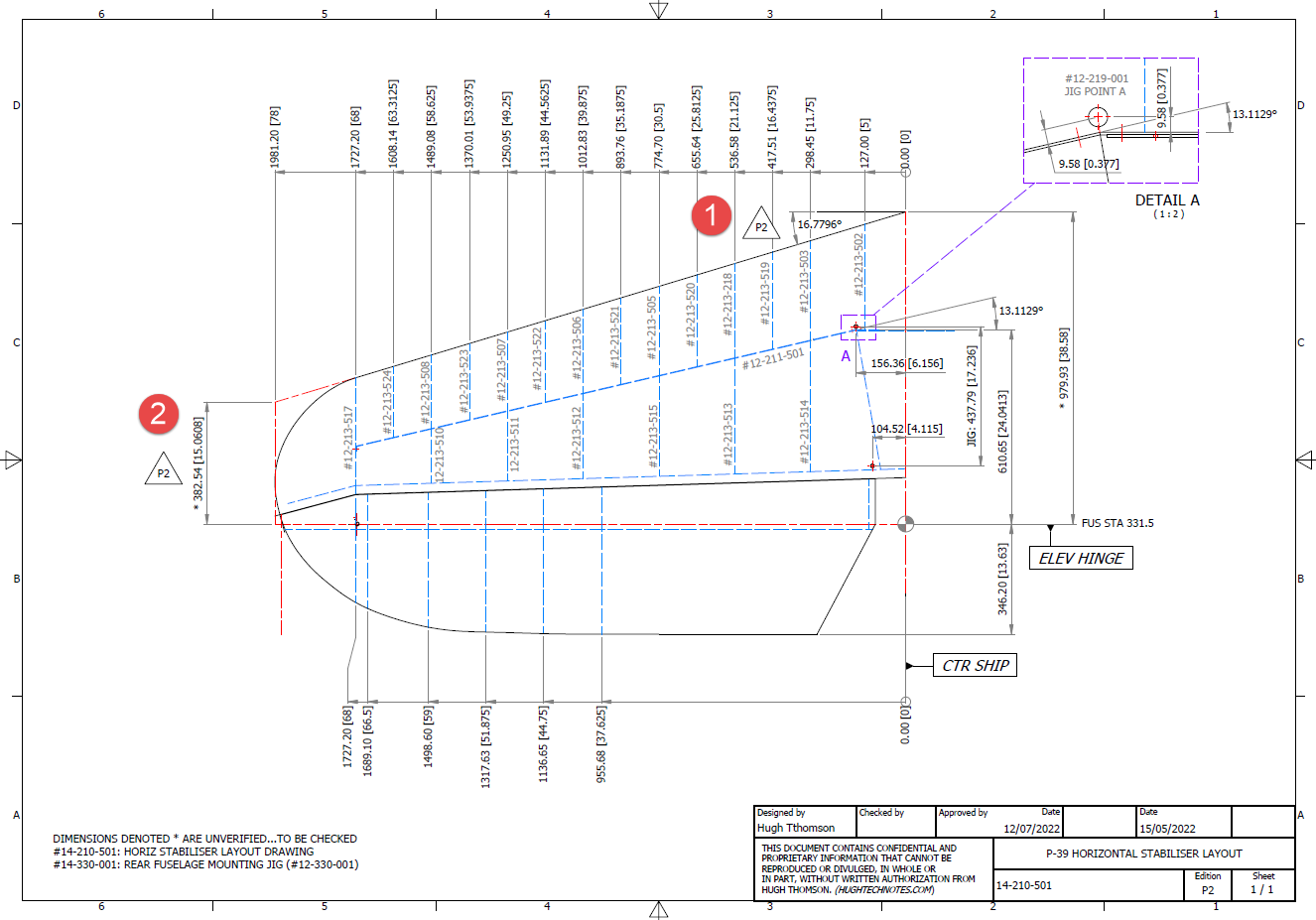
In a previous post, I covered the significant new model for P-39 Airacobra. This model is fully inclusive of all aspects of the aircraft. Within this post, I mentioned the extensive study involved in determining the layout for the Horizontal Stabiliser; the dimensions of which were unclear in the available blueprints
I was particularly keen to establish verification for the leading edge angle and though I had written to a number of organisations that have the P-39; surprisingly none of them took the time to either acknowledge or indeed reply…which of course was disappointing. From my experience, the industry is normally very supportive with regard to technical inquiries.
I revisited the documentation I do have and established that relevant information was included in the NACA Wartime Report L-602 which gives the chord length at Sta 49.25. It turns out; from my initial assessment; that the dimension at “2” was barely 2mm out and the Leading Edge angle is now 16.7796 degrees.
I mentioned in my last post that this latest study is available now which also includes the original model; which was more of a 3D modelling exercise than a dimensional study.
The P-39 Airacobra new CAD/Ordinate study is an impressive project.
All inquiries as usual to; hughtechnotes@gmail.com
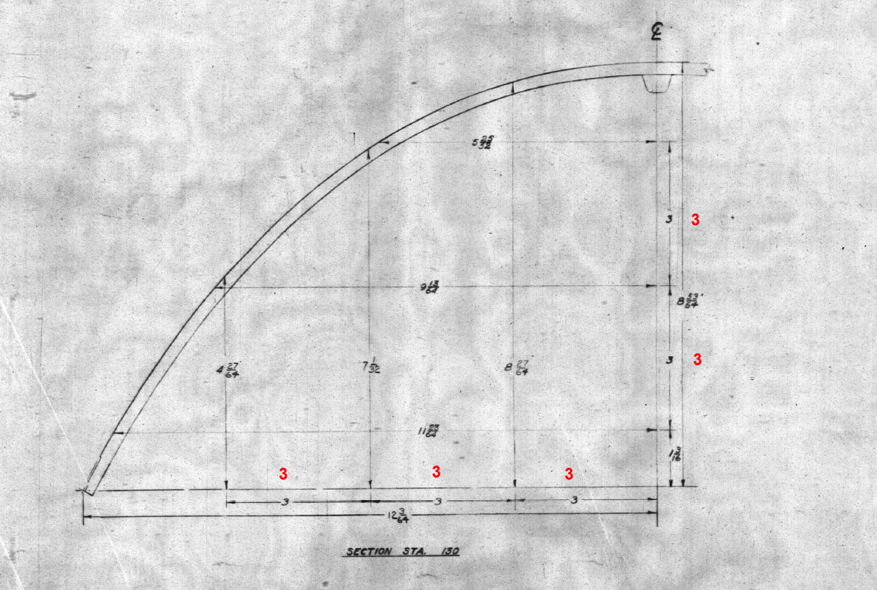
These are the basic profiles for the P-38 Cockpit Canopy glass panels derived from the XP-38 drawings. Knowing that there were differences between the prototype XP-38 and the production models I was initially reluctant to accept the XP-38 dimensions for developing the cockpit canopy. The production drawings do not contain any useful information to develop these profiles nor indeed was there any drawing stating the inclination angle of the windshield. There was also not enough information from the Lockheed ordinate drawings for the fuselage frames which left me with the only option to use the XP-38 information.
It transpires the dimensions on the XP-38 drawings are indeed pertinent to the production models. There are exceptions which relate to the side windows.
The drawing on the left is the P-38H side glass frame and you can see this is dimensioned as a radius value which differs from the XP-38, which is defined by ordinate dimensions. There is also a slight variation in the overall length, so I naturally presumed that there may be other variables that conflicted with the prototype model. The only way to know for sure was to build the model based on the XP-38 and cross-check against known information with the production models.
So after 3 days of frustrating intensive work, I now have the base model for the XP-38 glass profiles and I have concluded that the profiles for the front, top and rear panels dimensionally are compatible with production variants. The only area that has marginally changed is the side panels, although changing from ordinate to radial dimensions still retains alignment with the known fuselage frames.
Also worth noting is that Lockheed uses a 3-inch grid system for aligning all the fuselage components which are useful when you are trying to locate these panels where no location is noted…you just have to align the 3-inch offsets to the grid. Each of the 3-inch offsets on this drawing section for example can be matched with the full-size grid to locate the correct elevation for the top glass panel and so on.
It is actually a really clever idea and helps obviate any doubt about where an item should be located.
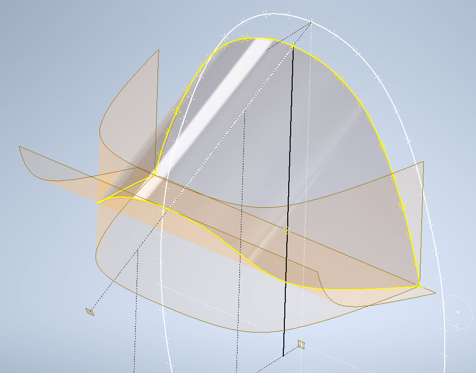
One further tip when working with these Lockheed drawings is that for plan views and elevation views there may not be enough dimensions to fully locate a 3d point for determining a complex curved line.
For the windshield, there was sufficient information in the vertical plane and the horizontal plane but as they were not related I could not derive specific 3d points from this data alone.
So I resolved to replicate this on 2 sketches and extrude a surface profile for each sketch. The intersection of the surfaces gave me the requisite 3d glass mold line.
The final check; that ensures this is correct; is to view the final glass panel along its axis to check that the curvature matches exactly with the top of the ordinate fuselage profile at STA 126…which it does.
For some reason, the ordinate dimensions are on STA 123 instead of STA 126 which means the end result will need to be projected to get the full glass panel model…I haven’t done that here. These are primarily dimensional studies and I tend to only include 3d models where this benefits the purpose of confirming data integrity. Oh by the way the inclination angle for the windshield is 27 degrees…don’t be sidetracked by the frame connectors that show 26.5 degrees…the reason for the 0.5-degree variance relates to the interface with the rubber sealing. Hopefully, you will find this useful.