Technote: 3D Printing-My Perspective
Recently, I acquired the Elegoo Centauri printer, and I would like to share some details about my experiences using it for aviation projects. When I received this printer, it actually sat in its box for about a week, as I was not quite ready to deal with the vagaries of FDM printing until fate intervened. I was also swamped with updates to the Grumman Goose and FM2 ordinate studies alongside development of the P-47. I didn’t really have much time for anything else.
Then the unexpected happened: my computer suffered a catastrophic hard drive malfunction. I opted to send the hard drive to a specialist company for data recovery; though technically I could have done this myself, the data was too important. So, having time on my hands, I set up the Elegoo Centauri and did some 3D printing.
I have been using resin printers for a few years, but I have never tried FDM printers. I used to believe that resin printing was the ultimate form of 3D printing when it came to dimensional accuracy and surface finishes, which FDM printers couldn’t match. However, I now realise I was mistaken!
This Elegoo Centauri is, quite frankly, a really good printer, a bargain at less than £300.
As I had an old laptop, I was still able to access my email and online accounts, but running any substantial software was out of the question on an antiquated version of Windows. So what I did was send CAD files from my online backup to my son-in-law, and he would slice them for me and send me the G-code for printing. This was sufficient for me to get started and explore the vagaries of FDM printing. Later, of course, when I got my hard drive sorted and my computer back up and running, I was then in a position to address several questions from my first foray, and this is what I will share with you today.
P-39 Airacobra – Planes of Fame:
As many of you know, and as previously covered in various posts on this blog, I have been assisting Planes of Fame with their P-39 restoration project. Where possible, replacement parts are manufactured to the original material specification; however, in some areas, particularly the cockpit control units, it was decided to opt for 3d printing replica parts. This is a static restoration, so this is quite acceptable. Though I often wonder with the plethora of advanced printing materials, whether 3d printing could be an effective replacement for flight-worthy restorations.
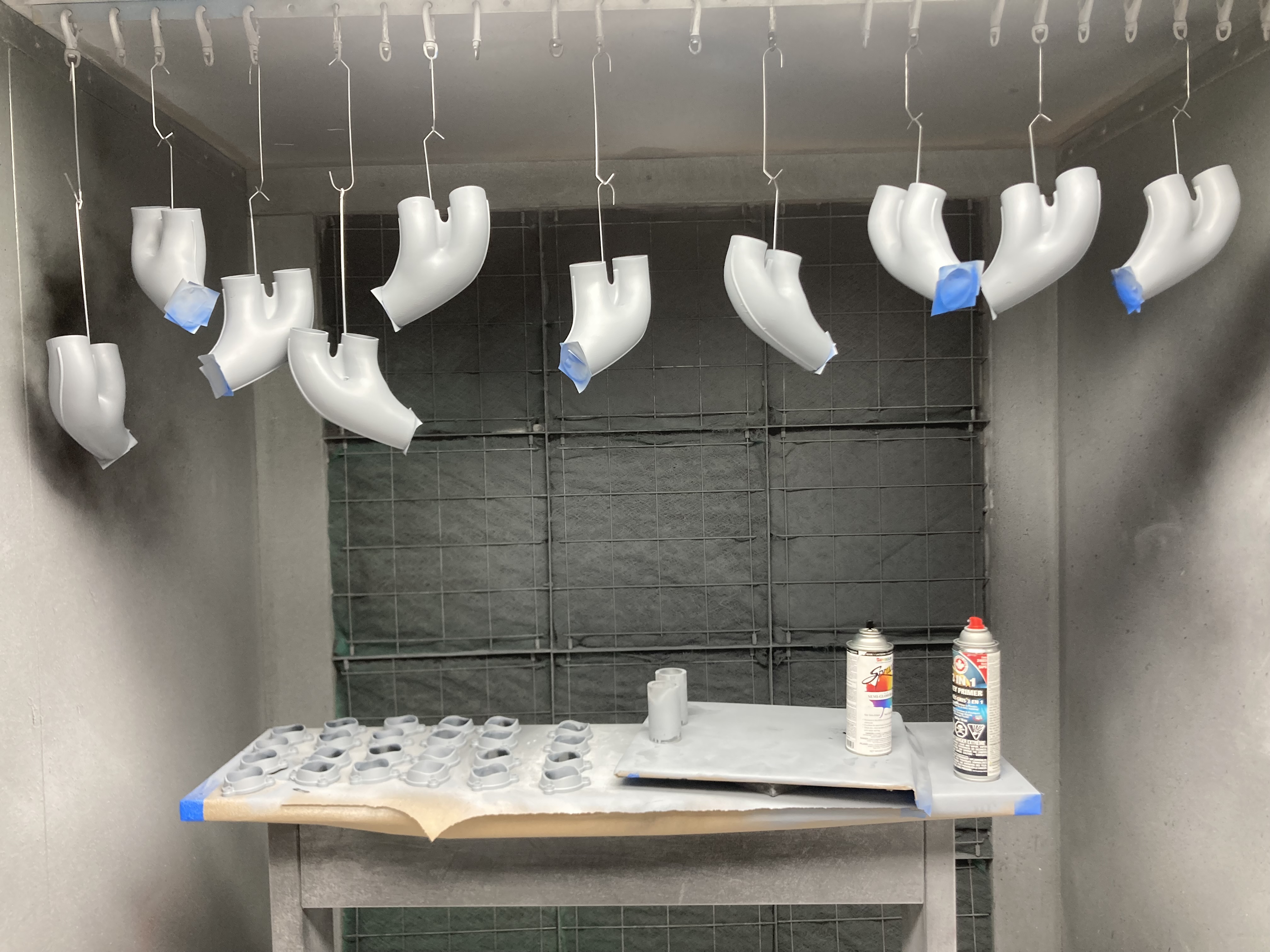
One of the first parts I printed when I got my computer back in working order was the Exhaust Stacks. Previously, I have had a post already on this, but the reason why I decided to print this was to explore metallic finishing options and acceptable material thicknesses.
Planes of Fame has access to an industrial-grade 3D printing facility using engineering-grade filament, the results of which are shown in the second image above. I figured that there was no way I could replicate that level of quality on a budget printer, but surprisingly, the Elegoo Centauri did remarkably well just using PLA+.
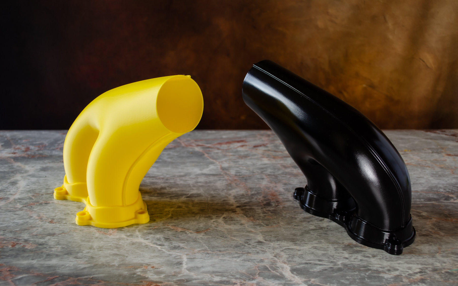
When I developed this CAD model, the exhaust wall thickness was set to 1mm…this was to make it easier for Planes of Fame to adjust the minimum wall thickness to suit the industrial printing preferences. I actually decided to initially print this at the 1mm wall thickness to see how well the Centauri handled thin walls. I was pleasantly surprised that, other than a few minor imperfections, the print came out really well. However, as this exercise was more about exploring metallic finishes, I decided to print it at 1.6mm wall thickness to give me some latitude for sanding. The black version in the first image shows the result of applying Filler Primer; 2 coats of sanding with 80, 120 and 320 grit sandpaper, and then applying 2 coats of black gloss. To achieve the metallic finish shown in the second image, I rubbed in graphite powder. There are several cosplay videos on YouTube showing how this was done on items like the Mandalorian helmet.
The surface should ideally be completed with a clear coat, but I don’t have any of that. The finish, I think, is quite dark and could be improved to be more aluminium-like if the paint were Gloss Grey instead of Gloss Black. I shared these details with Planes of Fame; I understand they may opt for the latter.
Custom Supports:
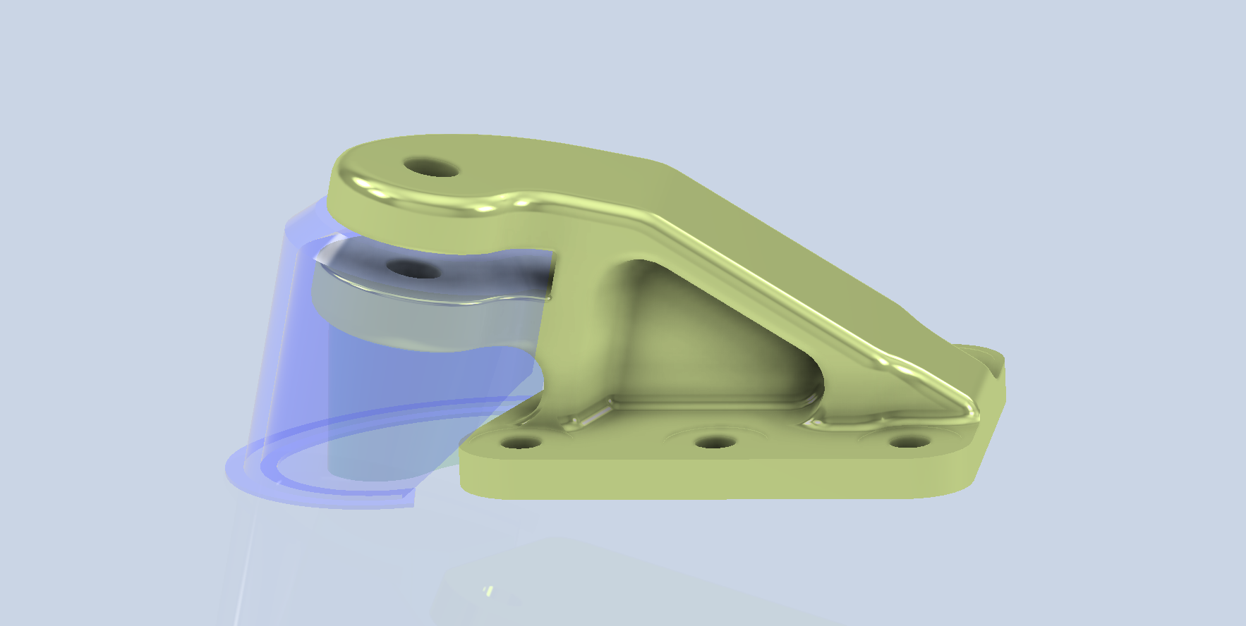
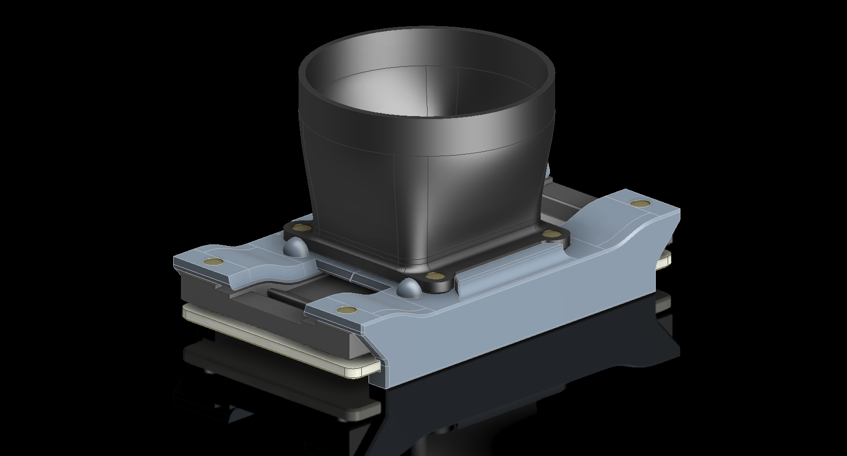
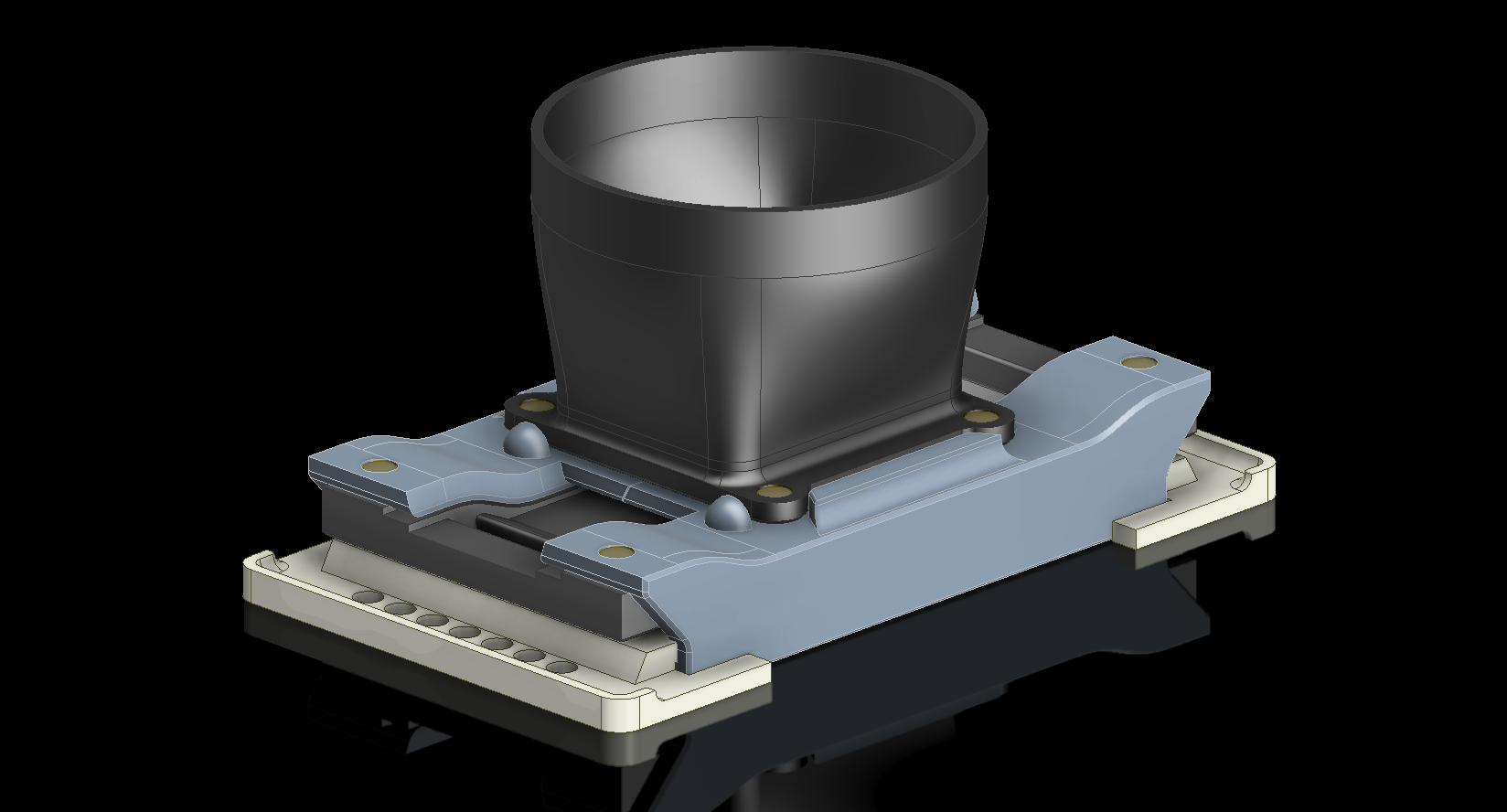
For the Exhaust stacks, I used the slicer Organic Tree supports, which were fine, but there was some stringing evident on the inside surface. I decided to explore options for custom supports instead to achieve better results. Again, working with a P-39 part, this time the pilot seat top support bracket. I should note that Planes of Fame has this same model; however, they will be making this from aluminium.
The first image shows the comparison between the slicer standard tree supports and using custom supports. Looking at the circular portion, the item on the left shows an irregular surface from the tree supports, whereas the version on the right shows a much more refined, consistent surface from using custom supports. The second image shows the custom supports created in CAD.
From my experimentation with generating custom supports that a gap of 0.24mm when printing at 0.12mm layer height works quite well. There is some consensus that one layer thickness would be an optimal gap, which may be applicable if the surface is planar to the base; however, in this instance, there is a small incline, and I find that 0.24 works well with the supports easy to remove.
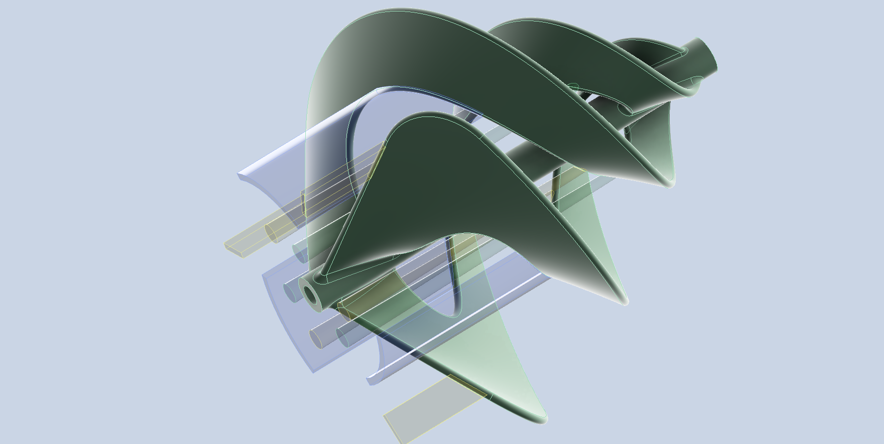
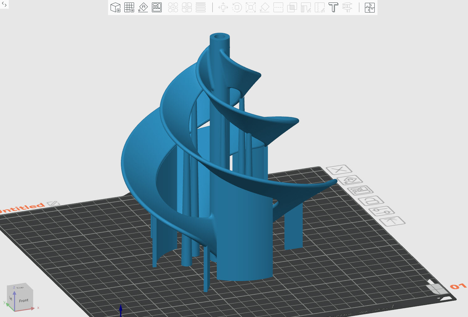
I also did some experimentation with another model, completely unrelated to Aviation, and this was for my wind turbine project.
Supports are necessary when the threshold angle is less than 30 degrees. Additionally, I’ve included extra supports to enhance stability, as the model may flex during printing due to the thin blades. I often find that a combination of custom supports and standard tree supports works well on more complex models.
Minimum Wall Thickness:
I touched on this with the Exhaust Stacks, and though 1mm is the recommended minimum wall thickness for 3D FDM prints, you can go thinner. There is a setting in most slicers called “Spiral Vase” or similar. What this does is produce a print with a wall thickness equal to the nozzle diameter. I tried this with a surface model for the Vertical Stabiliser for the Grumman Goose at 1:10 scale, and it actually worked quite well.
The downside is that this setting ignores any internal ribs that may be in the model and only prints the outside wall. I imagine there may be some uses for this in aviation modelling, but to be honest, without internal rib supports, there is probably too much flex. I should note that layer adhesion remains good, and the surface finish is smooth.
I intend to explore workable solutions for achieving minimal wall thickness and thus reducing the weight of model RC aircraft. As my main line of work is compiling all the known key dimensional information for the various aircraft and presenting this information in a concise, accessible format and in CAD, I see this as a natural extension of these studies.
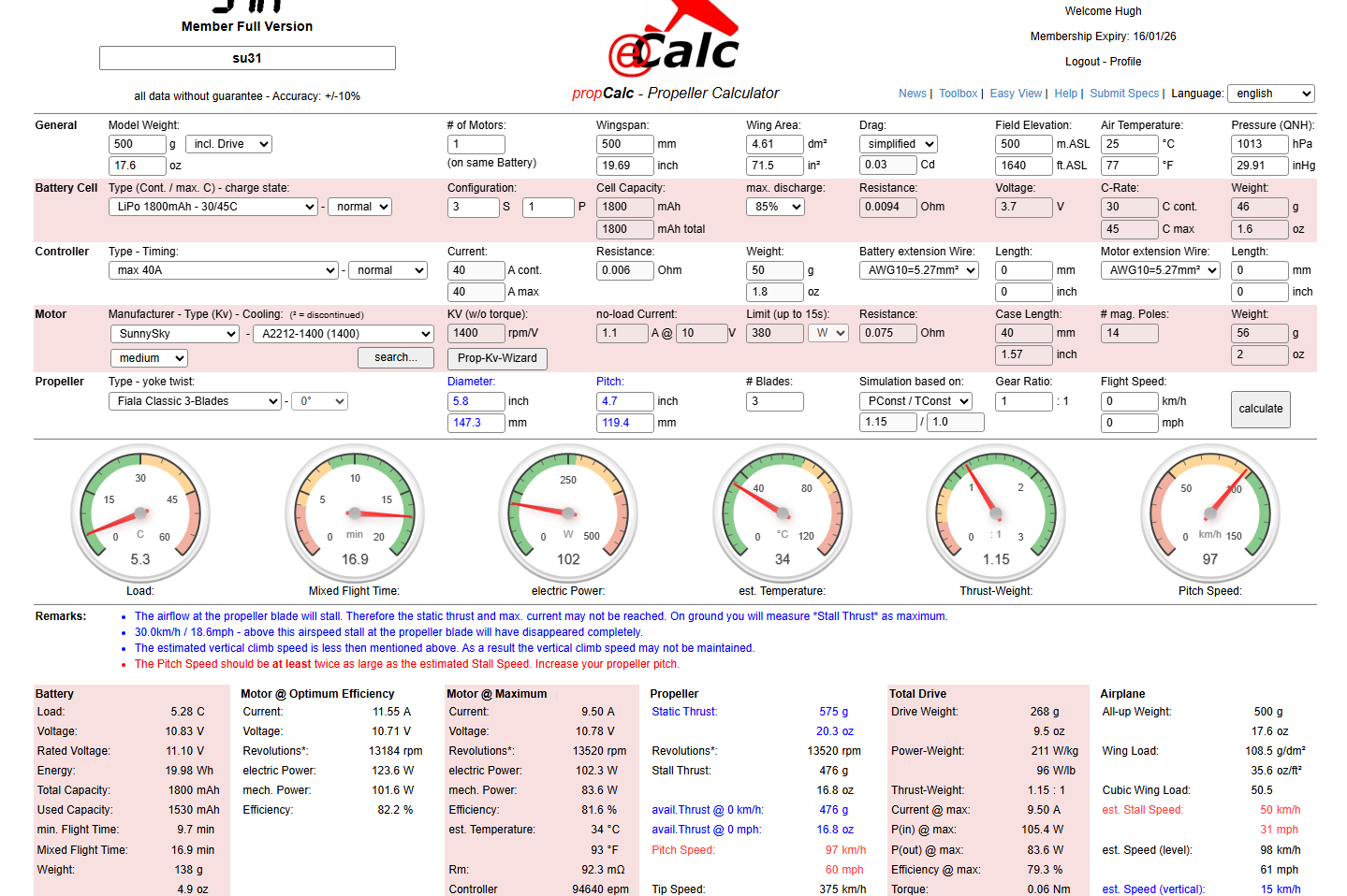
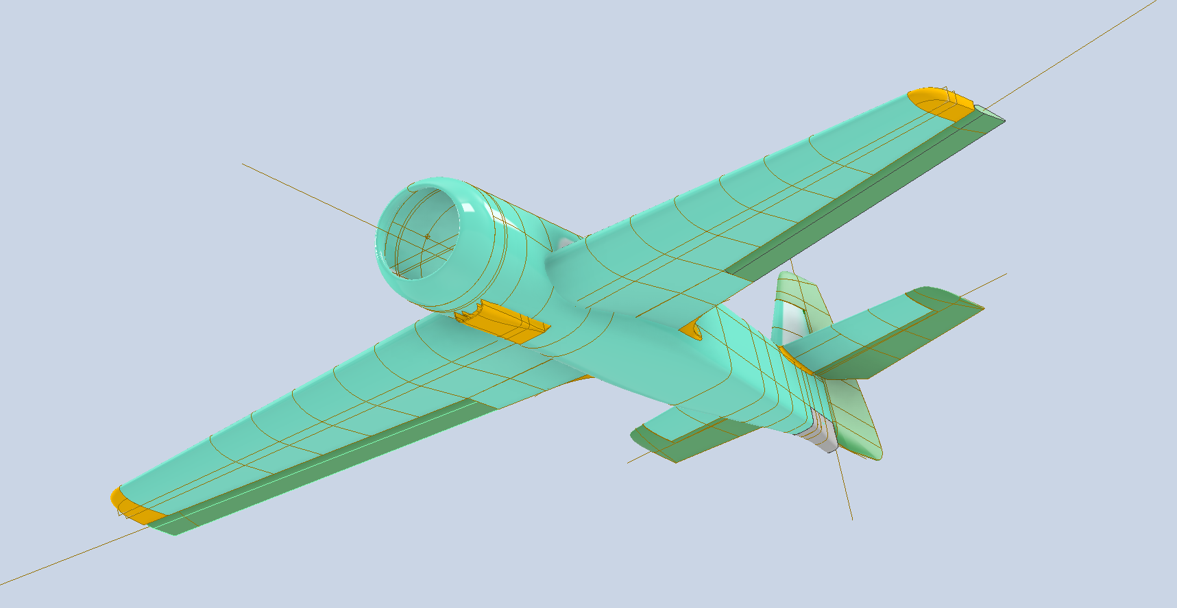
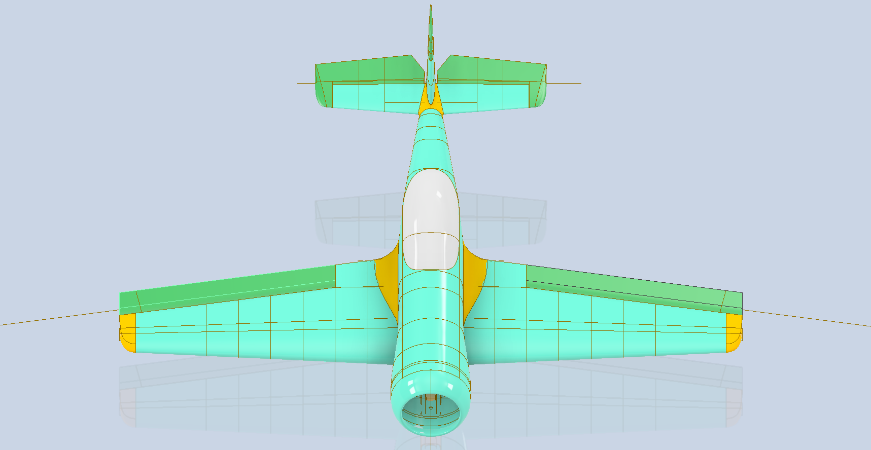
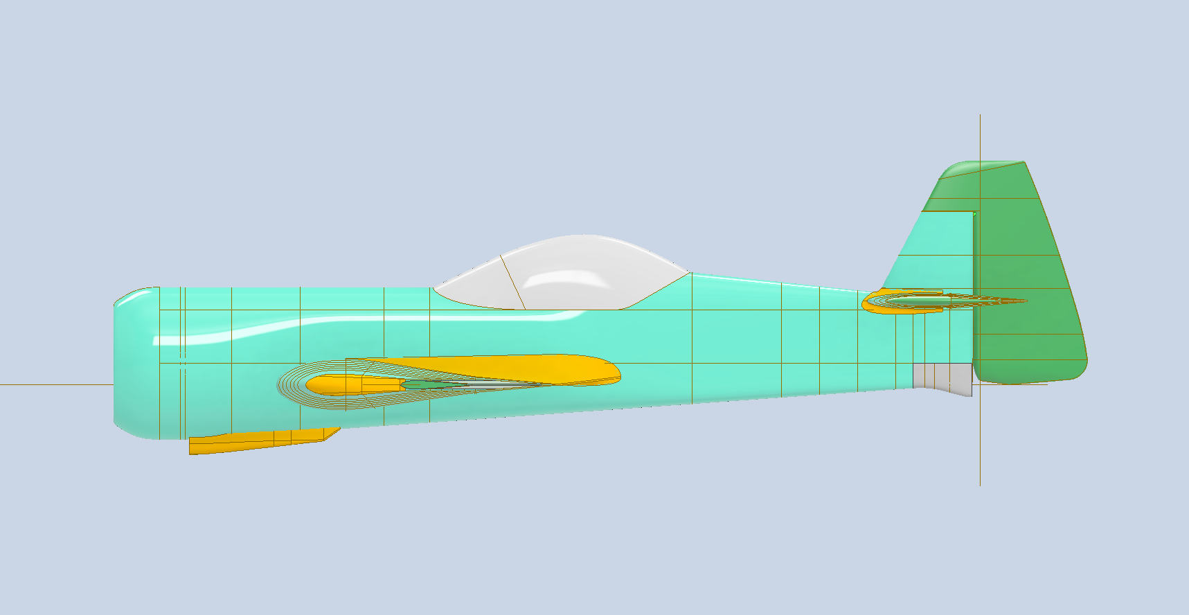
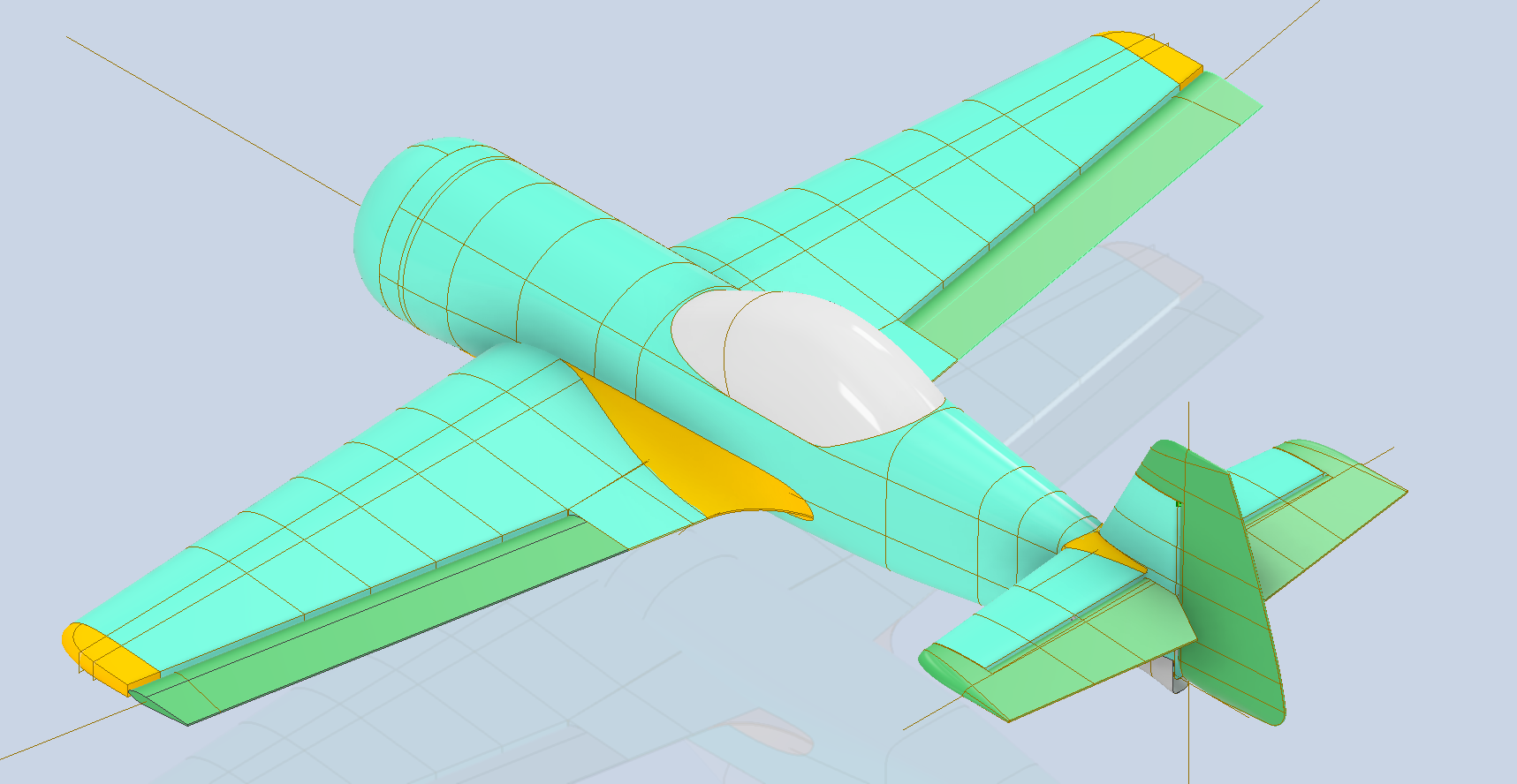
I already have several surface models (SU-31 and L23 Blanik) that can be easily scaled and adapted to produce accurate replicas for RC flight. The key to this is when scaling to then apply material thickness to the ribs, frames and surfaces that will be suitable for 3D printing whilst maintaining structural integrity with minimal weight. My current theory is that 2 x nozzle diameter for minimum wall thickness and 3 x minimal layer thickness may work.
My work on this issue is in the very early stages, and I will dedicate a specific post to this with my suggestions and samples of the end product.
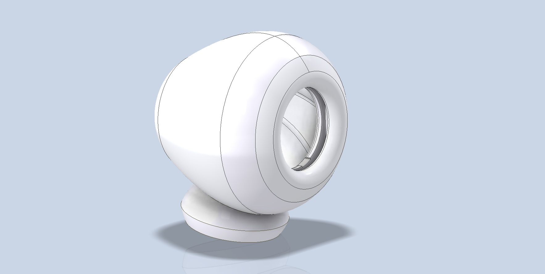
Finally: Printing Dowels:
This is something I only ever did on my resin printer due to the possibility of snapping along the layer lines. However, there is a solution for successfully printing dowels on FDM printers. I tend to use dowels a lot for aligning individual parts of an assembly.
For my desktop speaker projects, the body parts are aligned using dowels. As you can see, the dowel has 3 flat sides which can then be laid flat on an FDM print bed to enable printing with layer lines longitudinal to the axis and thus preventing splitting.