The Real Value of the CAD/Ordinate Datasets: Often Overlooked!
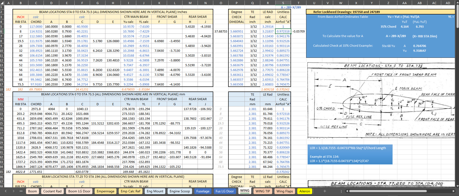
For many of my aircraft projects listed on the CAD+Blueprints tab, I offer comprehensive datasets of ordinate dimensional data in inches and millimetres listed in Excel spreadsheet tables. This data is extracted directly from original blueprints, verified by development in CAD, and, in many cases, verified by accurate recalculation.
This is the real value of these datasets, many of which took days or even weeks to compile. As an Excel spreadsheet, the X,Y, Z data is easily cut and pasted into your CAD system of choice, instantly providing point datasets that define fuselage frames, wing ribs, cabin contours and so on. It is that easy and saves you many days and weeks of trawling through blueprints and extracting the data piece by piece yourself.
The format of the tables replicates the same layouts as the data presented on the original blueprints, where applicable. So the data is easily cross-referenced for verification.
To give you a clearer picture of what to anticipate, the screenshots above showcase typical coordinate datasets for the P-38, presented in an Excel spreadsheet format. These datasets feature organised columns and rows, making it easy to navigate through the intricate details associated with the P-38’s specifications and performance metrics.
There is one caveat: there is a small cost involved. I have overhead expenses for software licenses and for running this blog Ad-free. I rely on donations and the sale of datasets like this to help cover those ongoing costs.
The Excel spreadsheets provided are fully adaptable and not restricted in any way, allowing you to modify them to meet your specific needs.
I wanted to take a moment to share this brief article that emphasises the true value of the CAD/Ordinate datasets. My aim is to shed light on how these datasets can be instrumental in enhancing your project and productivity. With their rich features and detailed information, the CAD/Ordinate datasets can provide invaluable insights and support, making your work not only more efficient but also more effective.
All datasets are supplemented with CAD models derived from them in commonly used formats, such as DWG, to assist you further.
This project aims to document and preserve dimensional data for historical aircraft, currently working on models such as the P-47, FM2, and Grumman Goose, alongside two glider projects. Utilizing archival blueprints—often of suboptimal quality—we employ precise digital reconstruction techniques to ensure the accuracy of aircraft structural data. The goal is to support restoration efforts, research, and educational initiatives in aviation history.
3. Objectives:
Digitally reconstruct and verify the dimensional data of historic aircraft.
Provide comprehensive documentation for restoration, museum displays, and aerospace research.
Develop methodologies for extracting accurate data from degraded blueprints.
Expand the available reference library for aviation researchers and engineers.
4. Significance & Impact:
Historical Preservation: Ensures that legacy aircraft remain accurately documented for future generations.
Educational Contribution: Supports aerospace research institutions and museums with validated technical data.
Collection and analysis of historical blueprints and microfilm archives.
Use of CAD software to recreate accurate aircraft structures.
Cross-referencing archival data with existing dimensional records.
Collaboration with restoration experts to validate findings.
6. Challenges & Solutions:
Suboptimal Blueprint Quality: Implement specialized image enhancement and measurement techniques.
Funding Limitations: Seek partnerships with aviation museums, historical organizations, and aerospace institutions.
Data Validation: Engage with experts to cross-check reconstructed aircraft dimensions.
7. Funding Request & Justification:
The project has been independently funded to date, but rising operational costs present financial challenges. Support is requested to sustain ongoing research, enhance documentation quality, and facilitate broader distribution to historical and aviation institutions.
8. Potential Collaborations & Sponsorships:
Aviation Museums: Partnerships for data preservation and restoration projects.
Educational Institutions: Opportunities for research integration and student engagement.
Aerospace Industry Experts: Validation and application of documented data.
Fellow Enthusiasts and Donors: Acknowledge contributions, engage in peer-to-peer discussion and provide technical support where applicable.
9. Conclusion:
This initiative offers a critical contribution to aviation history by preserving precise structural data of historical aircraft. With adequate funding and institutional partnerships, the project will continue advancing research and documentation efforts for aviation scholars and engineers.
—————————————————————————————————
Contact Hugh Thomson via email: hughtechnotes@gmail.com.
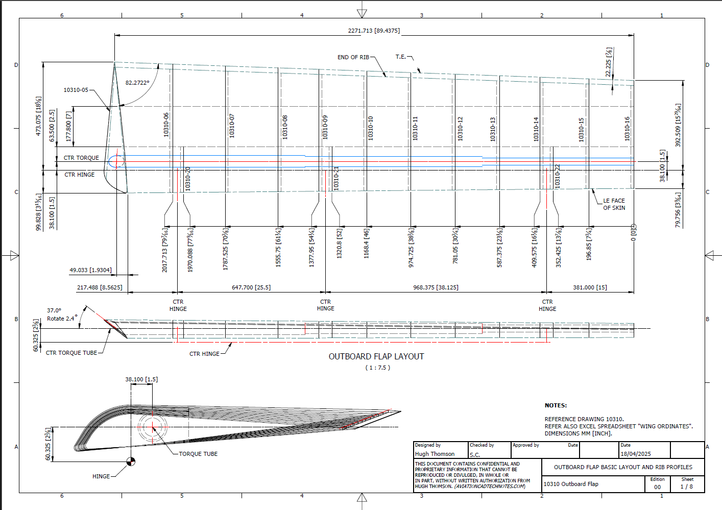
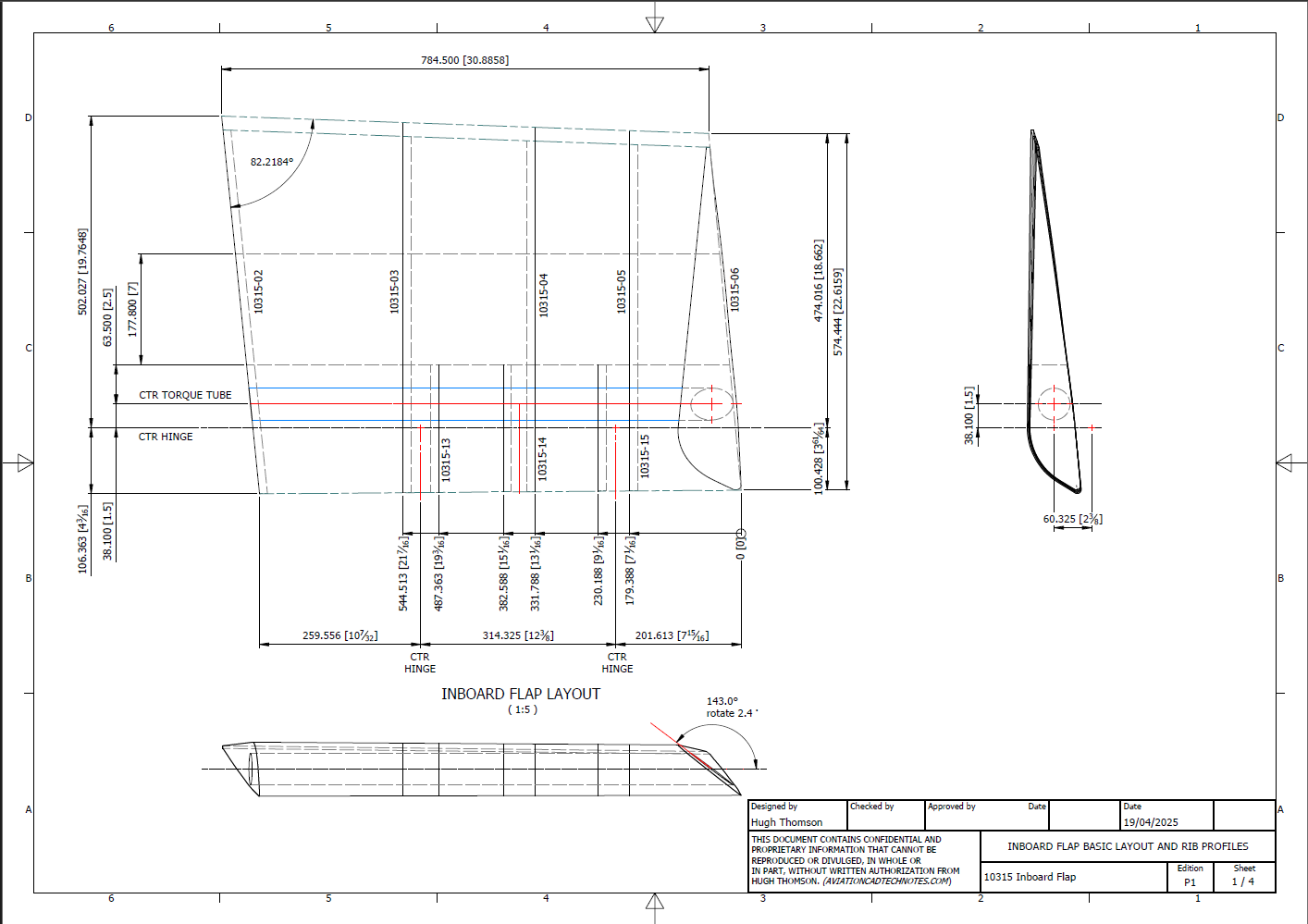
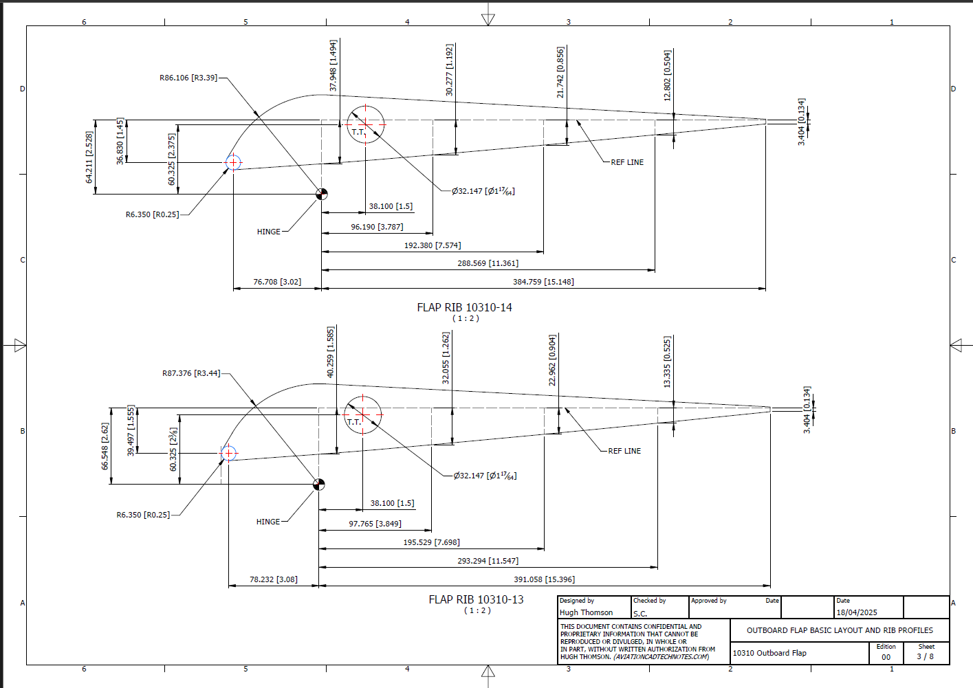
I have added new updates to the FM2 CAD/Ordinate dataset, completing assemblies for the Aileron, Outboard Flap, and Inboard Flap. In addition to the 3D CAD models, we have the fully dimensioned 2D drawings defining the profiles for all ribs.
Wing Layout and Rib Profiles:
The wing ribs comprise 3 separate rib profiles for the Leading edge, Mid-section, and Trailing edge. The detailed drawings show the complete profile and the individual component profiles separately. This will identify the blueprint drawing number in each case and the related blueprint scan file name.
Every drawing will be available as a full size Autocad DWG. All rib profile offsets are listed in a comprehensive Excel spreadsheet.
The CAD/Ordinate datasets are designed to offer detailed documentation of the dimensional information pertaining to the core profiles of various aircraft components. This includes elements such as fuselage bulkheads, cowls, vertical stabilizers, horizontal stabilizers, wings, rudders, flaps, ailerons, and elevators. Essentially, these datasets provide all the dimensional information needed to develop the main profiles for aircraft construction.
The research studies were conducted to fill in important gaps in information and to clarify unclear details. Often, data on blueprints can be difficult to read, making it necessary to record and analyze the bulkhead or rib profiles in CAD. This process helps accurately determine the correct dimensions.
The examples of ordinate dimensions above are not necessarily the worst; in fact, there are truly poor examples that exist. To tackle these issues, we should start by recording the known dimensions in Excel and making educated guesses about the worst examples. Next, we can create each profile in CAD. This CAD profile will give us a clear visual representation of any anomalies in the curvature, which can be further analyzed through curvature analysis to identify low and high spots. This process is done for every rib and bulkhead profile where we have ordinate dimensions.
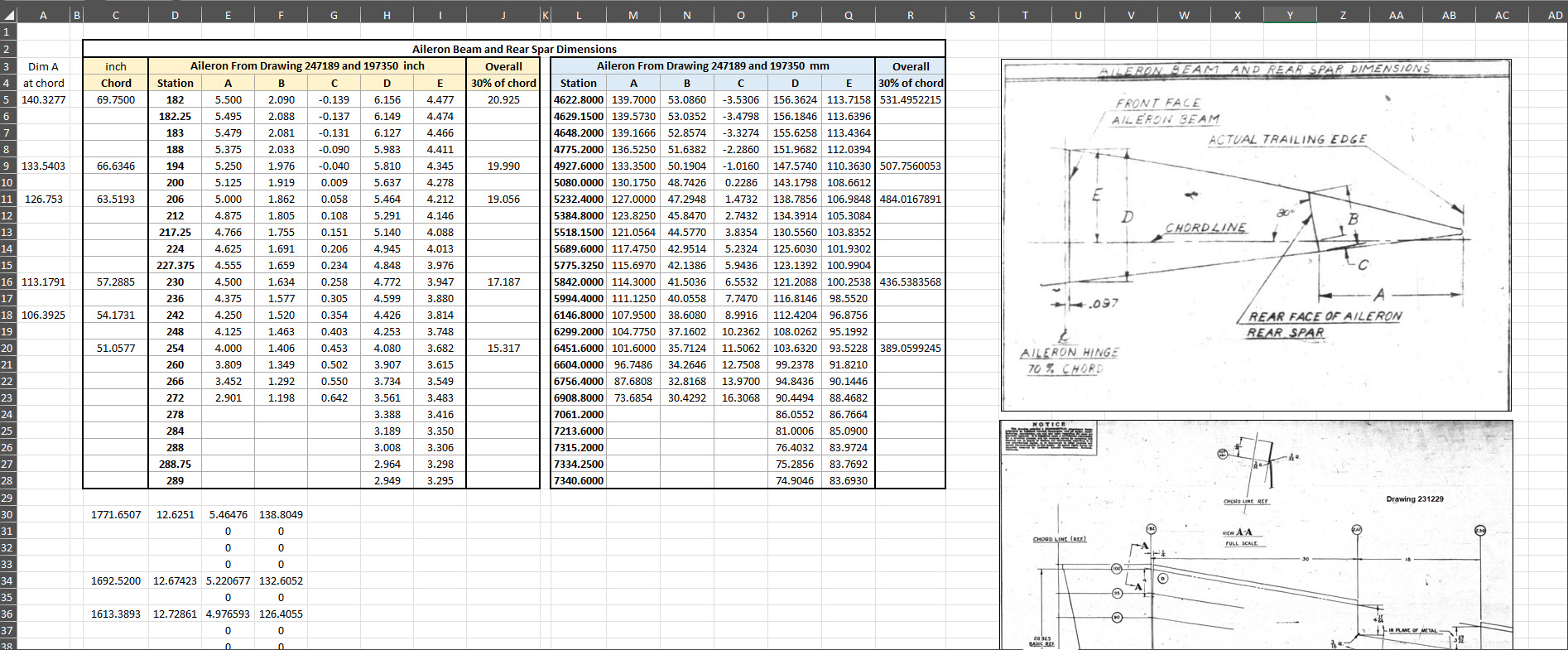
The spreadsheets above are typical examples of CAD/Ordinate datasets. The first spreadsheet contains the Ordinate record for the P-38, while the second one features the Aileron sheet for the FM2. You may notice a Linear Regression analysis table included in the FM2 sheet. Initially, determining the individual profiles of the ribs or bulkheads is just the first step; we now need to assess the assembly of all these components and check for proper alignment.
Each drawn sketch profile in CAD will serve as the border for containing a surface patch.
There are two primary reasons for doing this. First, it provides us with a plane that can be converted into a working surface, which can be utilized in any CAD product. Secondly, it provides us with a tangible element that we use to check assembly cross sections at key locations for alignment checks.
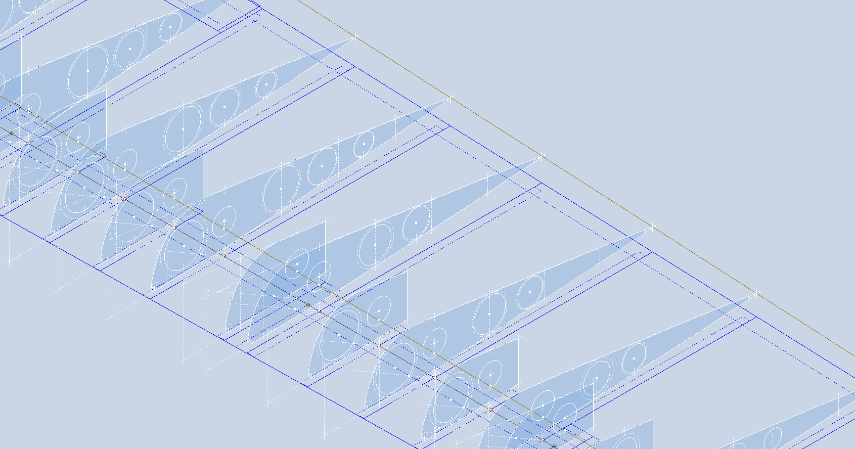
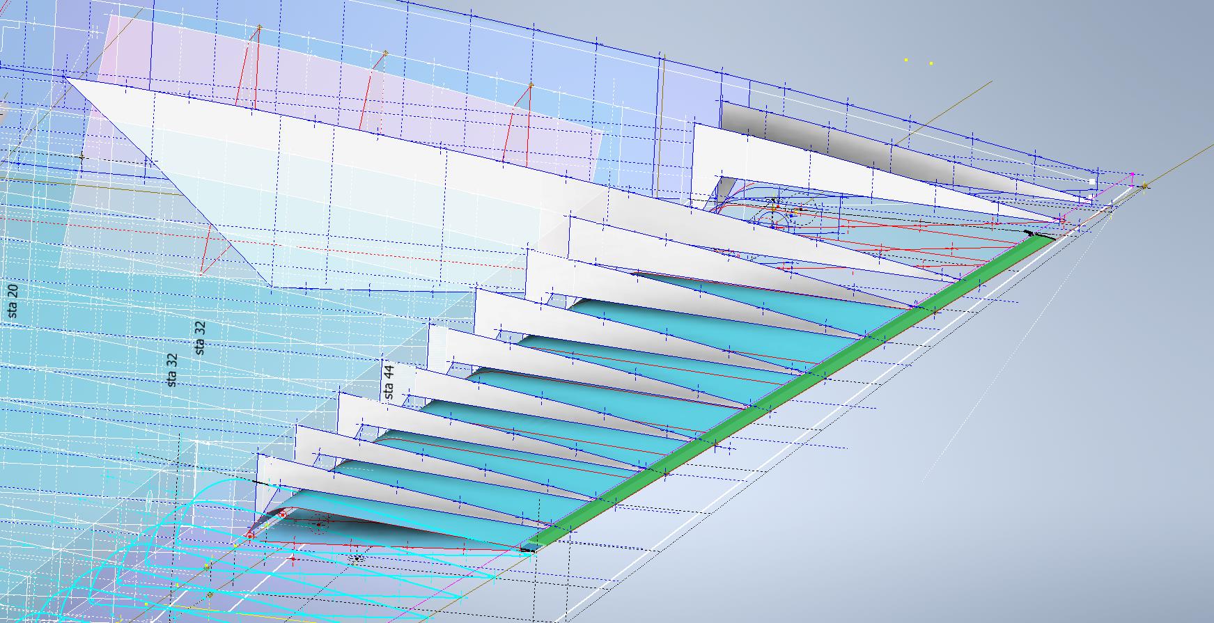
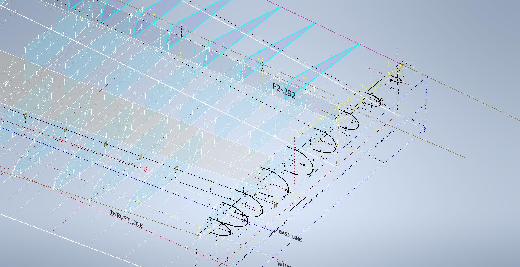
For example, consider the wing of the FM2. The wing assembly has been converted into a part file, and cross-section sketches were created at various chord locations: 30%, 60%, 70%, and 80%. Each sketch utilized the “Project Cut Edges” function to generate a cross-section of each rib. As shown in the second image, the array of lines representing the rib cross-sections provides a visual aid to identify high and low spots on the wing assembly. By creating a surface plane for each rib, we were able to generate these cross sections effectively. There were a few high and low points, which were double-checked and rectified.
If we require additional verification and strive for precision, we could use Excel’s Linear Regression to generate the coordinates for a Best Fit Line and make adjustments as needed. However, this approach may be excessive since our primary goal is to clarify the original blueprint data and apply it to identify appropriate rib and bulkhead profiles within acceptable parameters.
We can also use Linear Regression to give us an overview of how the ordinate profiles align with one another and to identify any discrepancies. Typically, acceptable parameters are within +/- 0.01 inches (or 0.254 mm), as specified by the dimensions on the blueprints, which usually only provide accuracy to two decimal places. Sometimes, as was the case with the P-51 and P-38, we had key design parameters that allowed us to calculate the exact profiles for each wing.
Validating dimensional data is crucial because the actual wing construction may not always match the accepted specifications. The design specifications for the FM2 call for a NACA 23015 airfoil at the root and a NACA 23009 airfoil at the tip. You might be surprised to learn that the NACA 23009 is a modified version of the standard 23009. Nothing is therefore assumed or taken for granted.
The CAD/Ordinate datasets are the result of extensive and thorough research and analysis, often taking many months of work, sometimes around the clock. These spreadsheets include every known ordinate dimension for various aircraft, gathered not only from blueprints but also from manuals, reports, and even correspondence. The CAD/Ordinate packages also include various 3D CAD models in various formats, including 3D DWG and fully dimensioned 2D DWG. All documents provided are fully editable so you can adapt the information to your work processes.
For more details on using the Ordinate spreadsheet data for your own CAD systems, see my earlier post here: Ordinate Overview
With over 45 years of experience in structural and mechanical engineering, my expertise influences everything I do.
In summary, the purpose of the CAD/ordinate datasets is the result of intensive work and research to provide the user with correct usable data that can be utilized in any CAD system.
When you buy CAD/Ordinate datasets and Blueprint collections from me, you support my ongoing research to provide the most comprehensive and probably the most accurate dimensional information about various aircraft. This blog and my research work would not be possible without your support.
The Grumman Goose project is both challenging and frustrating; it is definitely not a straightforward aircraft to work on. I have primarily focused on updating the empennage, which includes the vertical stabilizer, horizontal stabilizer, rudder, and elevator. During the development of the ordinate study, I observed discrepancies in the documented locations of various components. Let me explain what I mean.
Upon reviewing the CAD drawings on the left and comparing them with the Maintenance Manual diagram, I noticed that the level of the ribs varies by 1/16 of an inch. This discrepancy caused me immediate concern, and I began to wonder where I might have misinterpreted the Grumman drawing data. Therefore, I felt it was necessary to review and verify the information.
Initially, we do not have any reference location information on the Rudder Layout drawing. Normally, you would expect reference dimensions to the fuselage centerline or a fuselage station reference, but there are none. We do, though, have locations of the Hinges on other drawings for the Station bulkheads and Fin layout which in turn will help derive location information for the Rudder.
The first image above is the bulkhead layout at Station 36, which specifies the centre of the hinges 1, 2, 3, and 4 relative to the Fuselage Ref Line.. The second image is the bulkhead at Station 33, which shows the dimension of 65 13/16″ to the top of the Lower Rib on the Vertical stabilizer Fin.
I am looking to verify the dimensions and locations of the rudder ribs and hinges in relation to the Fuselage Reference Line. To accomplish this, we will start with the information we have and determine what additional information we need. The first image confirms that the CAD drawings for the rudder accurately depict the positions of the hinges. The second drawing further supports this; the “Top of Rib” location refers to the lower rib of the fin which includes the locations of the hinge centers. At this point, we have established the correct locations of the rudder hinges from two different sources.
Having determined the hinge locations, we know that the ribs for the rudder are offset by 5/8″ on either side of those locations, which allows us to derive the final levels noted on the Rudder Layout CAD drawing. Does this mean that the Grumman drawings, and therefore the CAD drawings, are correct while the manuals are incorrect? Yes and No…let me explain…
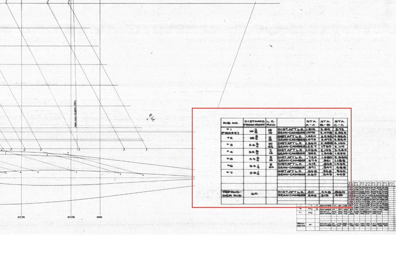
The first image is the Lines Diagram for the Vertical Stabilizer Fin Ribs. In the Table of Offsets, you will notice a list of dimensions from the “Root,” with the first rib specified at 10 7/8 inches. If we overlay these dimensions onto the CAD drawing, we observe a 1/16-inch discrepancy to the top of the first rib. However, all other sources, including those mentioned above and additional references not listed, such as the fuselage Lines layout, indicate that the top of the rib is correctly positioned in the CAD model (second image), contradicting the information provided in this Table of Offsets.
So what is going on?
We should take into account the revision history of the Grumman Goose development. If you examine their drawings, you’ll notice that they have made numerous revisions, some of which are labeled with letters as late in the alphabet as “R.” That indicates a significant number of changes.
I believe that various details have changed over the year, with the more prominent aspects being updated while the less prominent drawings remain unchanged. Regarding the manuals, it seems they were created early in the project, and it may have been considered too labor-intensive to update the level references. This aircraft is quite complex, and I can only imagine the effort involved in both its development and the ongoing updates to its design.
Whenever a small anomaly becomes apparent, I will make an effort to gather information from other drawings to verify the final result. This is one reason why these Odinate studies take so much time; it is crucial to ensure that the final study represents the most accurate dataset possible. If I were building a Grumman Goose replica, I would be using my datasets.
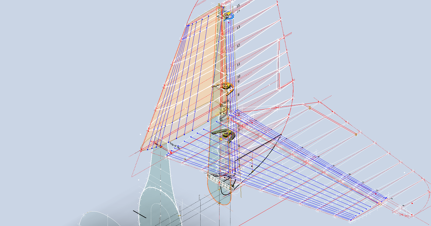
Progress Update 18th March:
A few screen shots showing the latest updates to the JRF Goose. The wing has been completely rebuilt with all dimensions verified.
On the CAD/Blueprint resource page, I have compiled a list of Ordinate Dimensional studies for various aircraft. The purpose of these studies is to gather all known dimensional information in a format that can be easily transferred to any CAD system. Additionally, they serve as a dimensional check to verify the designer’s intent and assess the accuracy of data from different resources, including blueprints, manuals, and correspondence.
Let me give you an example:
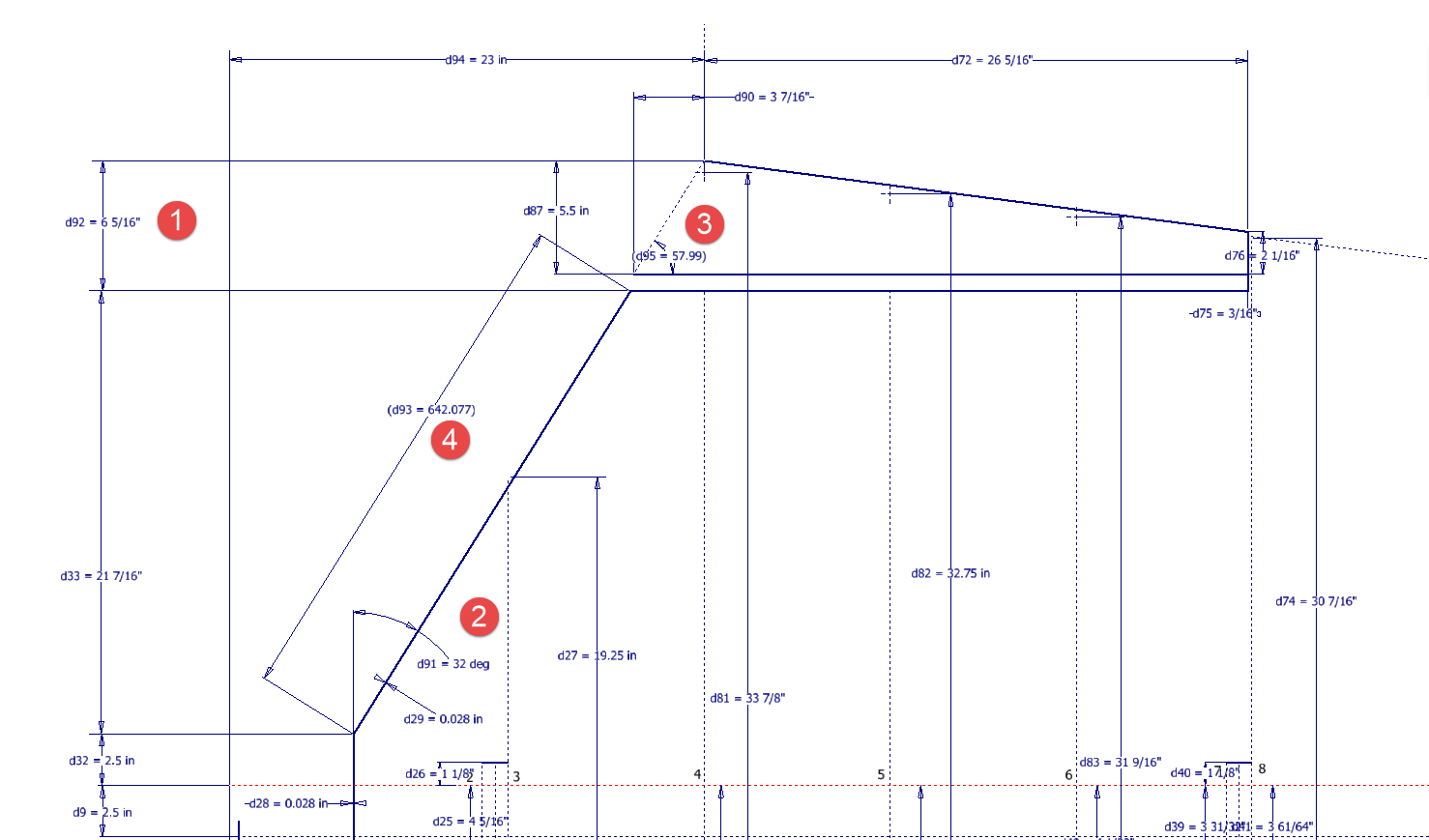
I am currently updating the CAD/ordinate dataset for the Grumman Goose and have already identified a few anomalies in the empennage. This document includes the layout study for the elevator, and you will notice that, based on the blueprint dimensions, the trim tab is incorrectly positioned.
At first glance, it may seem that the dimension labeled “1” is incorrect, as it appears to be the catalyst that causes the trim tab to go out of alignment. However, when we consider the length of the diagonal line labeled “4,” which measures 642.07 mm (25.27 inches), we find a discrepancy with the blueprint that specifies this dimension as 25 inches. Additionally, this measurement does not align with the chord dimension for the rib labeled “2.” As it stands, the angle of the sloping line appears to match at 32 degrees for both the trim tab and the elevator.
This type of issue frequently arises when working from blueprints for any aircraft project. To address it, further research is required, which will involve cross-referencing all part and sub-assembly blueprints in the affected area, reviewing general arrangement layouts, and consulting relevant manuals. It is essential to understand the design intent in order to develop the most likely solution. I have even extracted key information from correspondence that was important for the P-51 Mustang.
Small dimensional discrepancies are common in these projects, not only due to converting inch dimensions to millimeters but also because of typographical errors on the blueprints themselves.
The screenshots of the Ordinate spreadsheets display the dimensional information for the Horizontal Stabilizer and the Rudder. Several dimensions are highlighted in red, indicating errors on the blueprints that have been corrected. The dimensions marked in gray represent the measured dimensions from the CAD model. This discrepancy arises from the inherent accuracy of the specified dimensions, which may only be precise to 1/32″. As a result, minor deviations can occur during the CAD development process. Understanding these differences requires careful consideration of all key layout dimensions and material thicknesses, as they all influence the final derived dimensions. Nothing is taken for granted.
The CAD/Ordinate datasets compile all known dimensional information from various thoroughly researched sources, providing a comprehensive collection of data. This data is presented in editable spreadsheets, fully dimensioned drawings, and 2D/3D CAD drawings and models.
Elevator Layout Solution:
I have identified a solution regarding the layout dimensions. The dimension labeled as “1” is incorrect, but it is not the primary issue. Firstly, the Trim Tab has its own drawing #12530, which indicates that the overall length of the tab is 28.75″. This measurement is incorrect; it should be 29.75″. Additionally, other dimensions are also contributing factors.
In the bottom left corner, we find the specifications for the Hinge and Torque Tube, where two dimensions are marked with a tilde underscore to indicate that they are approximate. Generally, approximate dimensions are expected to be close to the actual measurements; however, that is not the case here. By adjusting the overall length of the Trim Tab along with modifying the approximate dimensions at the hinge torque, and also ensuring proper alignment with the known trailing edge, I have arrived at a workable and accurate solution.
Tech Tip: Using the Ordinate Spreadsheets:
I often get asked this and I have written about using the Ordinate spreadsheets before. Bumping it up to a more recent post, this one; I thought I would share a quick tip.
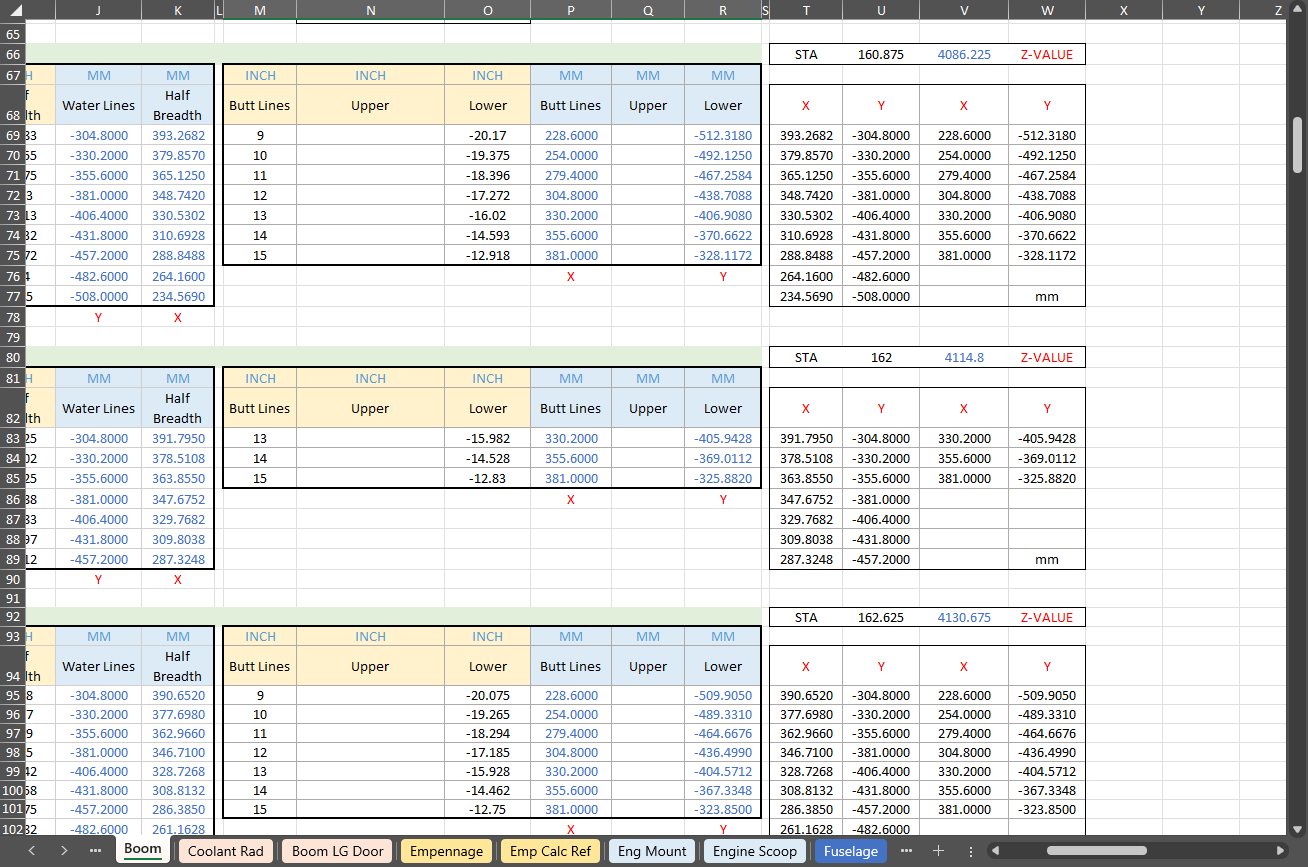
The Ordinate data spreadsheet is on the left, while the other is an empty spreadsheet that I use to paste data for a specific frame or rib that the CAD system can access. The empty spreadsheet just sits on my desktop, which makes it accessible.
Generally, the format of the data table is set out according to the original resource, which makes it easier to cross reference and check. This is not entirely ideal for CAD access as the X, Y coordinates are in rows and not in columns. The fix for that is easy, copy the data from the spreadsheet as required, select Paste Special in the destination spreadsheet making sure to select the “Values and Formats” and the “Transpose” options. The former ensures the data format remains the same and the purpose of the Transpose function is to convert data rows to columns. This gives us the data in X, Y columns ready for insert into the CAD system.
Note the “inch” header…I am using a millimetre template in my CAD system so I have to specify the unit of measure when I select from the first table. By the way, there is a second table that has all those values converted to millimeter anyway, so we could easily use that…in this case, you would not require a header row.
In other datasets, I have developed additional data tables in the spreadsheet, where I have transposed columns for the X, Y, and Z coordinates, such as those for the P-39.
I receive a lot of feedback from users about the spreadsheets, specifically regarding the time they save on projects since they do not have to manually input data themselves.
The ordinate dimensional study for the f4F/FM2 Wildcat will now be ready in January. This will include dimensional information for all the rib, strut, and frame profiles fully documented in 3D CAD, 2D drawings, and Excel spreadsheets. Probably the most accurate dimensional study available.
In January I will be taking this project and the P-39 Airacobra to the next level. The plan is to fully 3D model in CAD all the primary structural components for the wings, flaps, ailerons, elevators, rudder, fuselage, empennage, cowl, and landing gear; and then produce a 3D printed scale model at either 1:15 or 1:10 scale. The F4F empennage is already partially fully 3D modeled in CAD which gets us off to a good start in the New Year.
These models will be printed on an Elegoo Saturn MSLA printer capable of producing a 0.02mm accuracy. The resin I will use will likely be PLA with a 10% mix flex resin to minimize brittleness. This is an ambitious project and will take most of the year to complete.
Many of the components are thin-walled profiles which may have to be adjusted to suit the scale of the printed model. Some testing will be done to find the minimum thickness to achieve model integrity and maintain dimensional accuracy.
This project is something I have been thinking about for a long time which is only now possible with the incredible accuracy achievable by the latest 3D printing technology. The final 3D CAD model; suitable for 3D printing; will NOT be available publicly but I am open to the idea of private sponsors.
As usual, all inquiries to hughtechnotes@gmail.com
I have taken a break from the wing development whilst I await more information. So I have switched my attention to resolving the Canopy layout for the F4F/FM2 and true to form I have yet another bunch of questions. I often wonder how on earth they actually managed to build this aircraft.
First of all, we have a layout drawing showing the canopy dimensions…at first glance, it would appear that this will be a straightforward task. However, this is not the case.
We have a number of key dimensions that don’t quite add up…the dimension at “1” is shown as 29.25″ and the dimensions at “2” is 29/875″ but when you compare that with the offset dimensions from the Fuselage Station locations at “3” and “4” there is absolutely no way that “1” and “2” can be correct. The depth dimension at “5” is presumably along the line that would otherwise be defined by the dimensions “1” and “2” but as those dimensions are incorrect then what is this actual dimension relating to?
So I need to figure out what is going on here and therefore I thought I should check the track locations which should provide clarity and verification.
We do have a drawing that details the track components but there are no setting out dimensions for the track relationship to the fuselage. The only other drawing that shows the track is the Structural Assembly drawing…alas that does not help either. The fuselage section above the cockpit shelf is as shown highlighted in yellow. It shows the track and a number of frames that in my opinion are very important aspects of the design but what you see is the only information we actually have. You would think that something as important as a canopy track would be critical to warrant a detailed layout showing the correct alignments and setting out points…there is nothing there! I literally sat here one day reviewing every single drawing in my archive…all 8775 of them to find useful information.
It gets even more interesting as we continue this quest.
The forward section of the canopy has no location information so there is no context as to where this actually resides in relation to the fuselage. Furthermore, although we do have the dimensions for the windshield itself there is absolutely no setout information for the side and top glass surfaces. This is again an area that will require full 3D development, similar to what I had to do with the horizontal and vertical stabilizers. However, I have run into problems with that as well. At Sation 2; the key to getting this correct; is an offset dimension (highlighted in yellow) which is noted as 2.781″ or 2.834″ depending on whether you take into account insulation….so ideally in an “as fitted” condition you have to wonder what the correct fitted dimension should be.
As you can see I have started the 3D development of the cockpit and canopy to hopefully realize pertinent information from individual part drawings and fitting details to determine the missing information and verify the setout for the canopy. This is a lot more work than I anticipated but other than just giving up on this project it is my only option.
I have also reached out to various companies and organizations to try to source more information that will help establish the key parameters I am currently missing. This can be expensive and the reason why I rely heavily on your support so that I can find the answers to these important issues.
I am very close to finalizing the ordinate/dimensional study for the FM2 so it would be a real shame to give up at this stage.
Please help fund these projects so I can find answers for you. Get in touch as usual to hughtechnotes@gmail.com
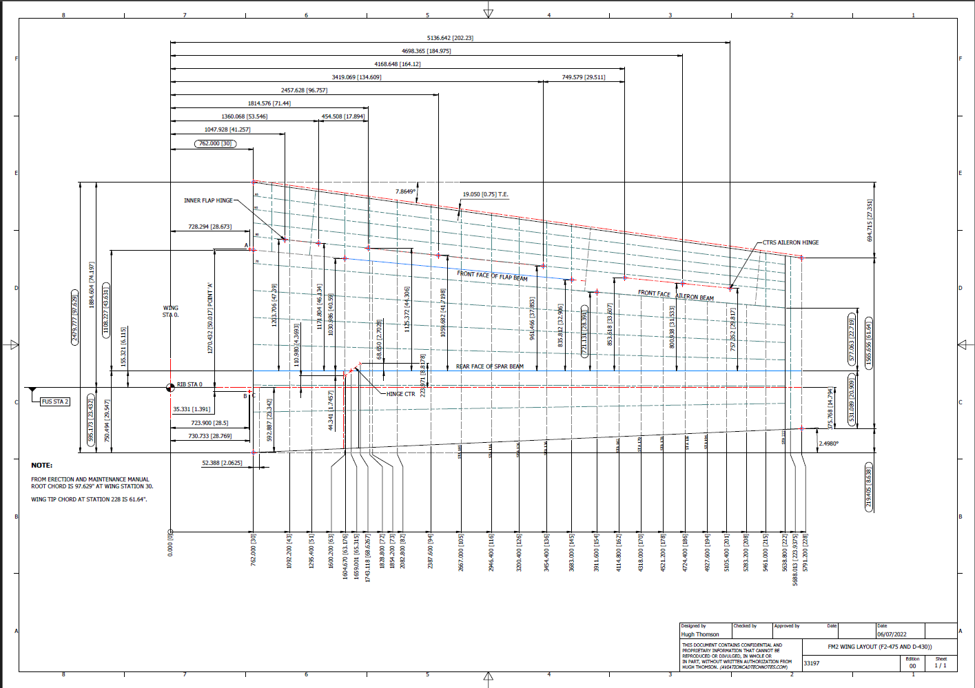
Since my last post, I have further developed the Wing layout which has revealed a number of key considerations that you may be interested in.
Wing Trailing Edge:
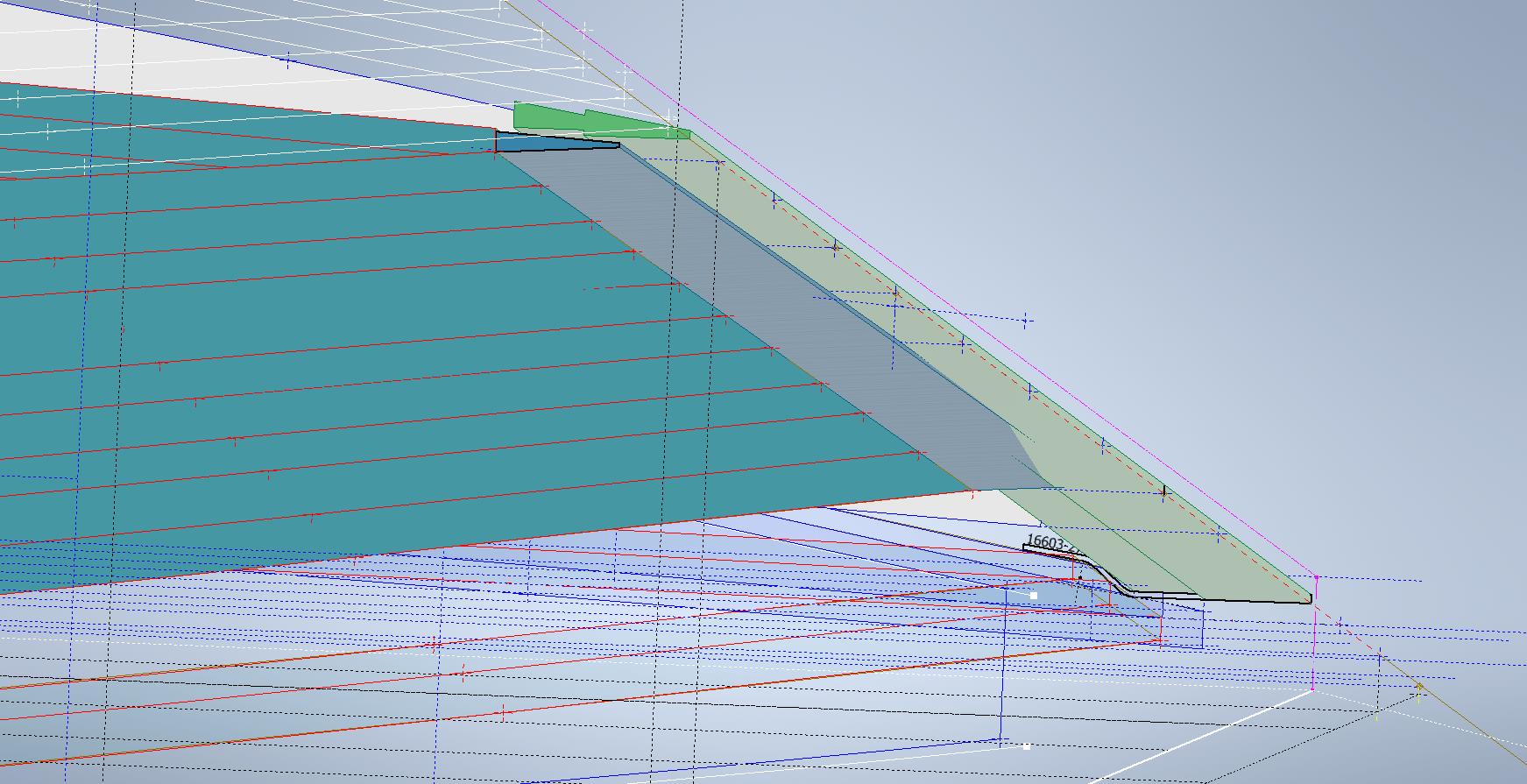
Other than a noted offset on the rib drawings there is no definitive alignment specified for the Wing Trailing Edge. What I found was the Wing Trailing Edge rib profiles were reasonably accurate from which I could determine this alignment.
The component shown in green is the Alcoa K14403 standard Grumman profile for the trailing edge. When I developed each of the wing TE profiles (white) there was a minuscule variation in the alignment, so I needed to determine the best-fit line through those points using Linear Regression Analysis. I could just have easily selected 2 random points from the wing TE profiles which would have been okay but I like to get this stuff right.
By using Linear Regression there is no guesswork or random selection it simply analyses the point coordinates and calculates a line that best fits all these known points. As we have 11 coordinate points to analyze the end result will be an accurate placement of a Trailing Edge line that represents the collection of known coordinate points. The column named Residuals is the offset from the known coordinates to this line. As you can see the max offsets are in the region of 0.3mm…well within normal fabrication tolerances.
Having now established a correct Trailing Edge I checked this against the flaps (cyan) to see how well the assembly aligns with this newly defined trailing edge. I noted a deviation of 2.2mm on the outboard edge towards the wing tip.
Flaps:
In the image above you can see how the flap assembly does not align exactly with the wing trailing edge. My first impression was that I had made a mistake with the model, so I rebuilt it resulting in the same deviation. So I checked the location of the hinges…they are dimensioned to 4 decimal places of an inch so for all intents and purposes they are exactly located. Further research reveals that there is a return spring on these flaps and I think what is happening is the flap layout is deliberately set out this way so the flap first engages with the wing at the control cylinder end and then the return spring engages closure with the outboard end…hope that makes sense. Grumman has used this type of spring mechanism to engage the closure of wing surfaces elsewhere at the wing folding mechanism.
I believe the geometry for the flaps is correct however my dilemma is whether or not to adjust the alignment to align perfectly for the future purpose of design analysis…and of course should there be any interest in the development of an RC model. One to ponder.
Wing Folding Web:
On the inner wing stub section, there is a sloped web plate attached to 3 triangular gussets. This is basically the mating plane for the wing stub and the main wing assemblies at the wing folding joint. This is one area that is not so accurately dimensioned…when you develop the triangular gussets there is a slight variation in the edge slope that this web plate is fitted to and similarly, the profile of the web plate is also marginally out. We are talking about fractions of millimeters but it does matter. I developed this area in a separate assembly where the wing ribs were lofted and then the triangular ribs and web plate were sectioned. Incidentally, the second image above is the only drawing (#7150645) that indicates the slope of this web plate at 50 degrees. You can also see the numerous datum lines that we have for setting out this wing that I mentioned in previous articles.
The mating portion of the outboard wing that engages with this web plate is the spring-loaded assembly I mentioned above…I have yet to do that part…will probably feature in a future article.
Wing Folding Hinge:
Just a quick update on the Wing Folding Hinge. I have this fully dimensioned now as an ISO View, Front and Side elevations which enables alignment checks with associated ribs and web plates. It is important that the rear face of the main spar aligns with the center of the hinge so these dimensions help establish this correct relationship.
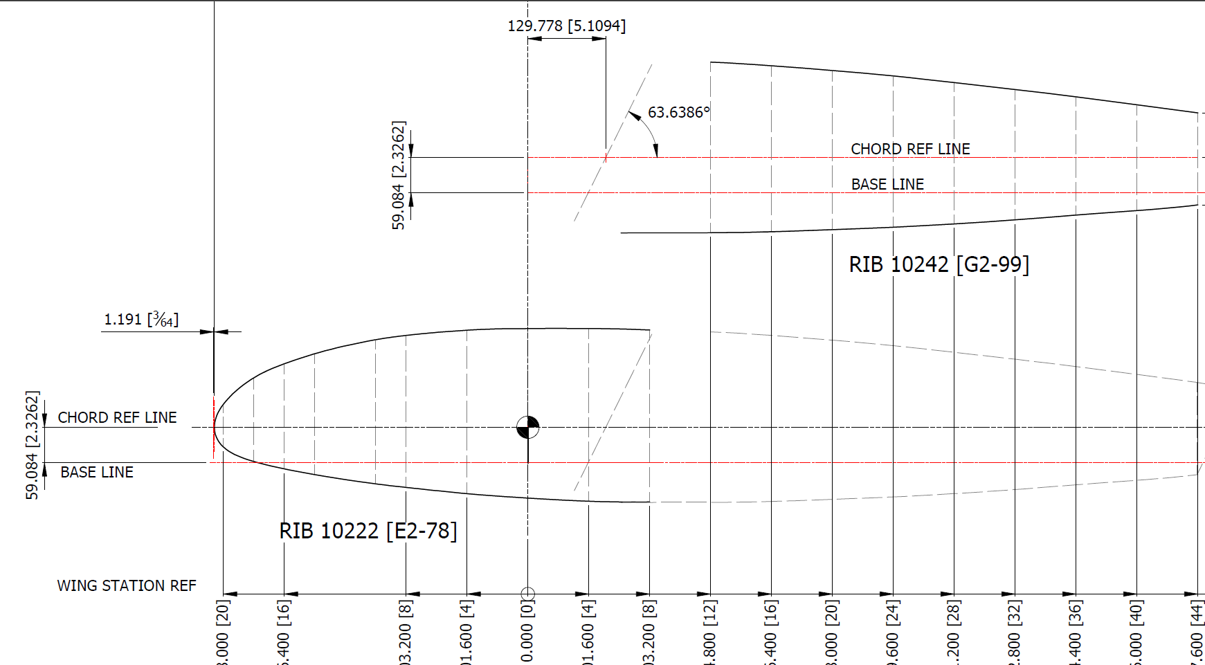
Wing Tip:
The wing tip sketch profiles are now drawn but there appears to be a slight mismatch with the wing tip rib profile at Sta 222. The Trailing Edge at 55/64″ below the Chord LIne was also puzzling as it did not align with the Trailing Edge line mentioned above. Again my first impression was that I made a mistake with the rib profile…drawn again…same result. I then checked the alignment with the Aileron assembly and whilst the wing rib TE aligns with the Aileron TE the Aileron does not align with the Wing Trailing Edge line.
This one is a bit more difficult to comprehend as there is no logical reason for the Aileron to essentially drop toward the Wing tip…yet the wing tip rib and aileron align well. Again I checked the hinge locations and they are exactly where they should be. I have been in touch with a number of museums and restoration companies to see if they have an explanation and also requested photographs along the edge of the aileron to visually examine the aileron alignment. I will get back to you on this one. By the way, I also carried out a linear regression analysis to determine the exact reference line locations for each aileron rib as a check.
This aircraft is surprisingly complex and whilst there may be perceived anomalies that at first cannot be explained there is usually a good reason for being the way they are. For example, the leading edge of the horizontal stabilizer has a negative camber towards the tip, essentially the leading drops….this is most unusual.
Finally, to make things even more puzzling the wing tip rib profile is not actually a NACA 23009…it is close in profile but it does match exactly…I believe this is a modified NACA 23009. Once I have all the ribs modeled according to the Grumman drawings I will calculate the wing rib ordinates to double-check the profiles…that will be a real pain and time-consuming thing to do as the ordinates are at 4-inch and 2-inch intervals along the chord and not by chord percentage as one would expect…so I need to transpose that data from the cad models to develop the equations for checking.
I have spent an incredible amount of time developing this wing, perhaps more than any other aircraft study I have done. This design is very complex and keeps throwing up small anomalies that at first are difficult to comprehend…it does require a lot of research to figure out the reasons why.
Update 17th Sept 2023:
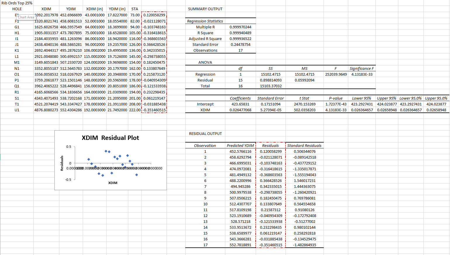
Wing Rib Ordinate Check: As mentioned above I have now carried out a check on the wing rib profile ordinates. Normally I would do this the same way as I calculated the wing rib ordinates for the P-38 Lighting but that is only applicable when you know for certain the root and wing tip rib profiles. The main point of this exercise was to determine the accuracy of the FM2 wing tip profile which is apparently different from the stated NACA 23009 profile.
I resolved to do this using Linear Regression Analysis from plotted points on the 15%, 25%, 50%, and 60% chord planes. These percent chord planes actually have to be determined separately because the wing rib ordinates on the Grumman drawings are incrementally spaced at 2″ and 4″ intervals which of course does give us the straight-line projections we need.
Typically I did this for the top and lower ordinates recorded from each rib at each chord plane and compiled the resulting data into a table in Inventor which was then exported to MS Excel for analysis. The analysis confirms that the wing tip profile is accurately drawn and the ordinates on the drawing profile are correct. I shall also do a similar exercise to check the dimensions of the main beam at the flap and ailerons.
Drop me a line for further information at hughtechnotes@gmail.com
Please consider making a small donation, every contribution makes a real difference.
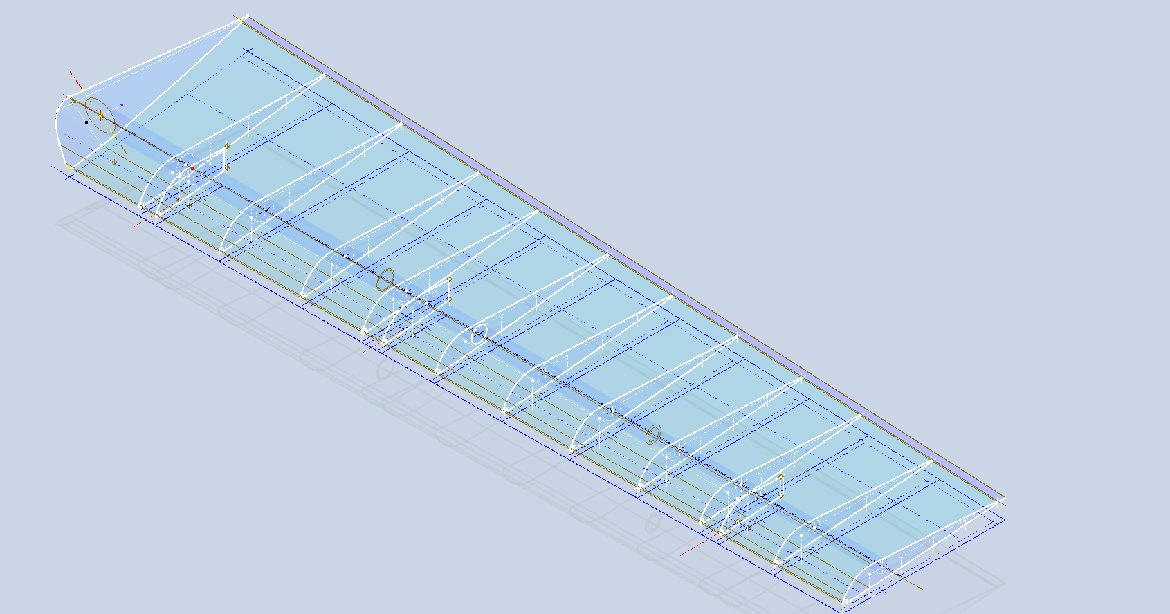
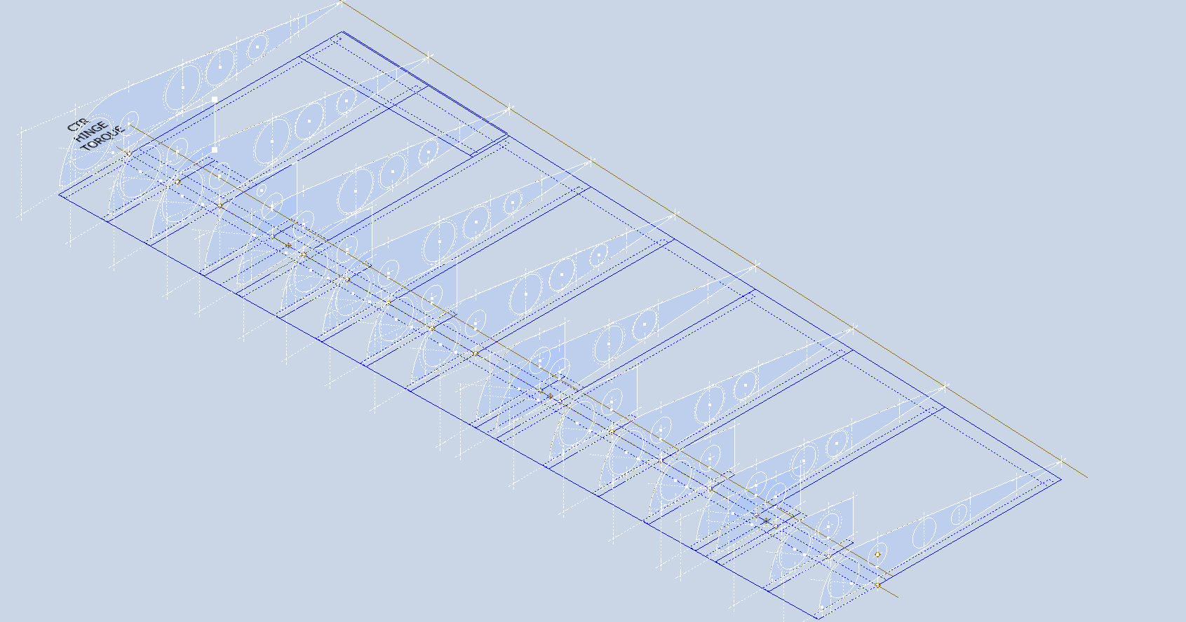
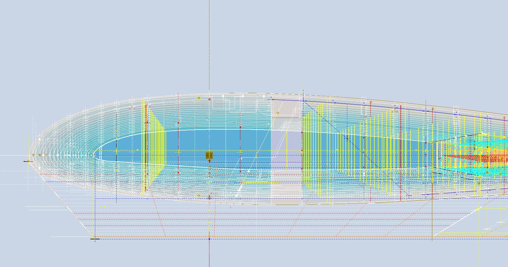
Developing this wing tip turned out to be more complex than I originally thought it would be. Because the model required a few interesting techniques I figured it is worthy of a quick technote that hopefully will assist others.
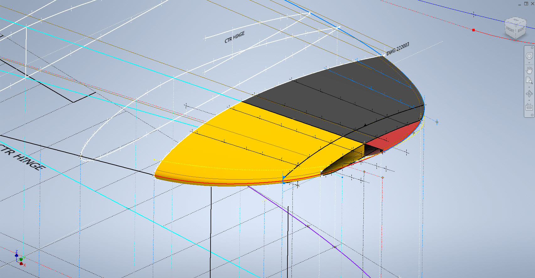
First, off the bat, you will probably have noticed the center partition which came about as a consequence of the development process. I will try to explain how this transpired…read on for more details.
What we have is essentially one main rib profile at Station 289 and 2 others towards the tip which you would normally just loft to achieve the finished surface assuming that the required outline guide rails were included in the initial data set. Actually in this case we didn’t have those curved outlines as a 3d profile only a 2d outline on the plan view. Even with the guide rails in place just lofting the full rib profiles did not work due to the continuity of the rails in a circular manner that prevented a successful loft.
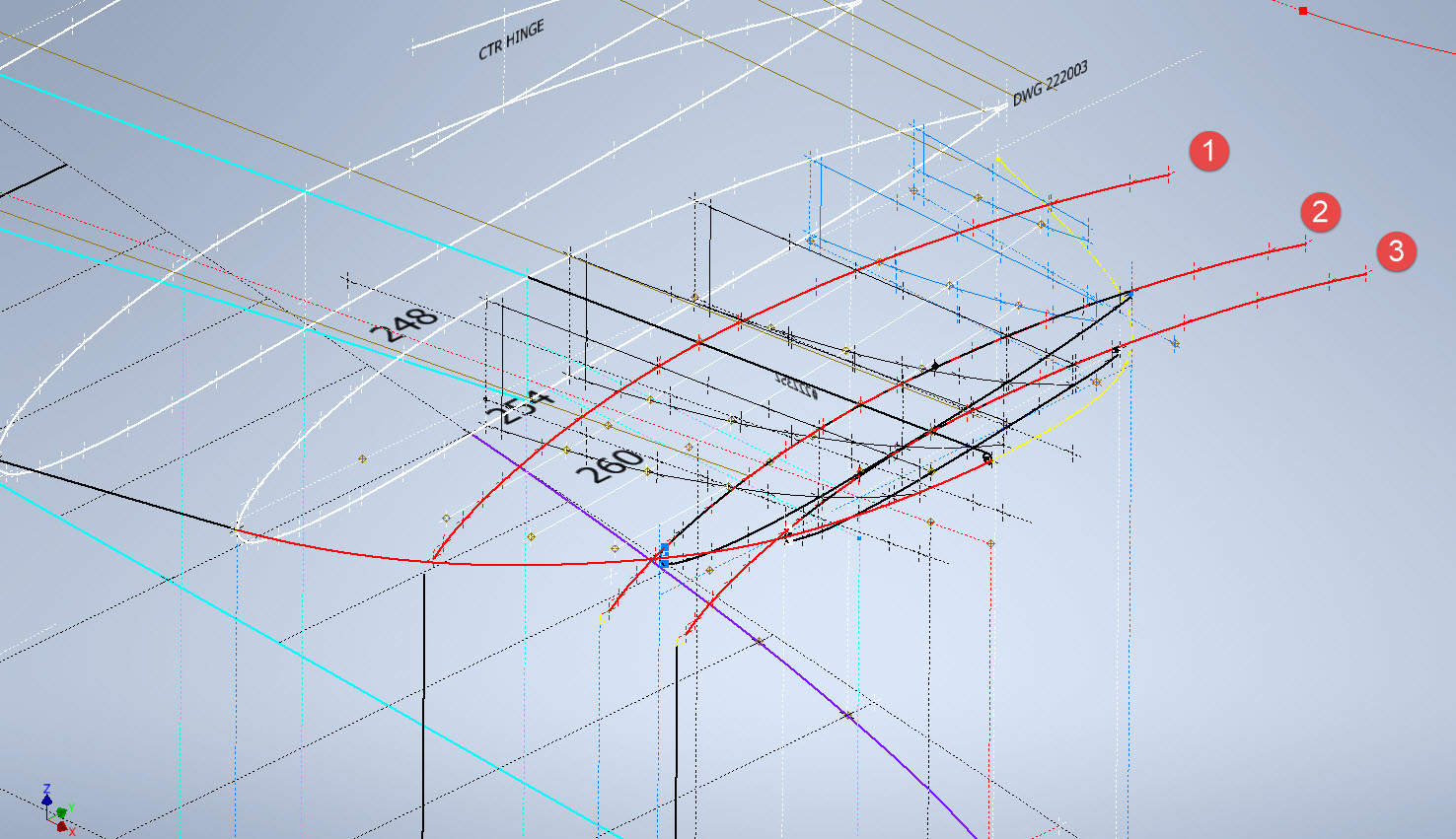
By the way, the circular guide rails at “A” and “B” were generated as intersection curves using a side profile (top right in the background) and the plan profile to derive the resulting intersection lines. I initially wanted to extrude the 2d plan profile and build a 3d curve on the face of the surface but I was unable to apply a tangent constraint to align with the Leading and Trailing edges…so my only option was a 3d intersection curve.
Realizing that a full rib profile loft was not achievable I decided to fill each rib profile with a patch surface and then split the surface at the main beam intersection, which incidentally is perpendicular to the ribs. So this gave me a patchwork of surfaces fore and aft that I used as surface profiles and lofted each section as shown using the guide rails at “A” and “B” and the center rail at “C”…this created the partition I mentioned in the beginning.
Once the main fore and aft sections were modeled I then proceeded with the extreme tip which was simply a case of again adding a surface patch to the small projecting profile in the center and lofting the surfaces separately as before. Occasionally when you have problems with lofting it often helps to break it down into more manageable chunks.
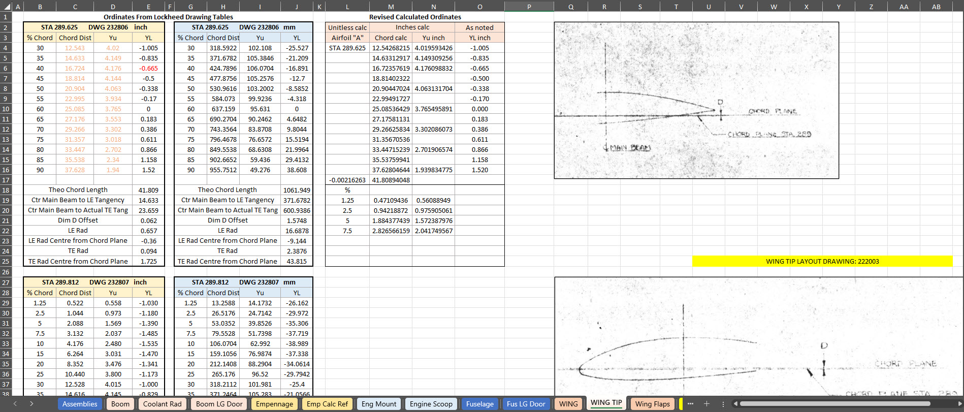
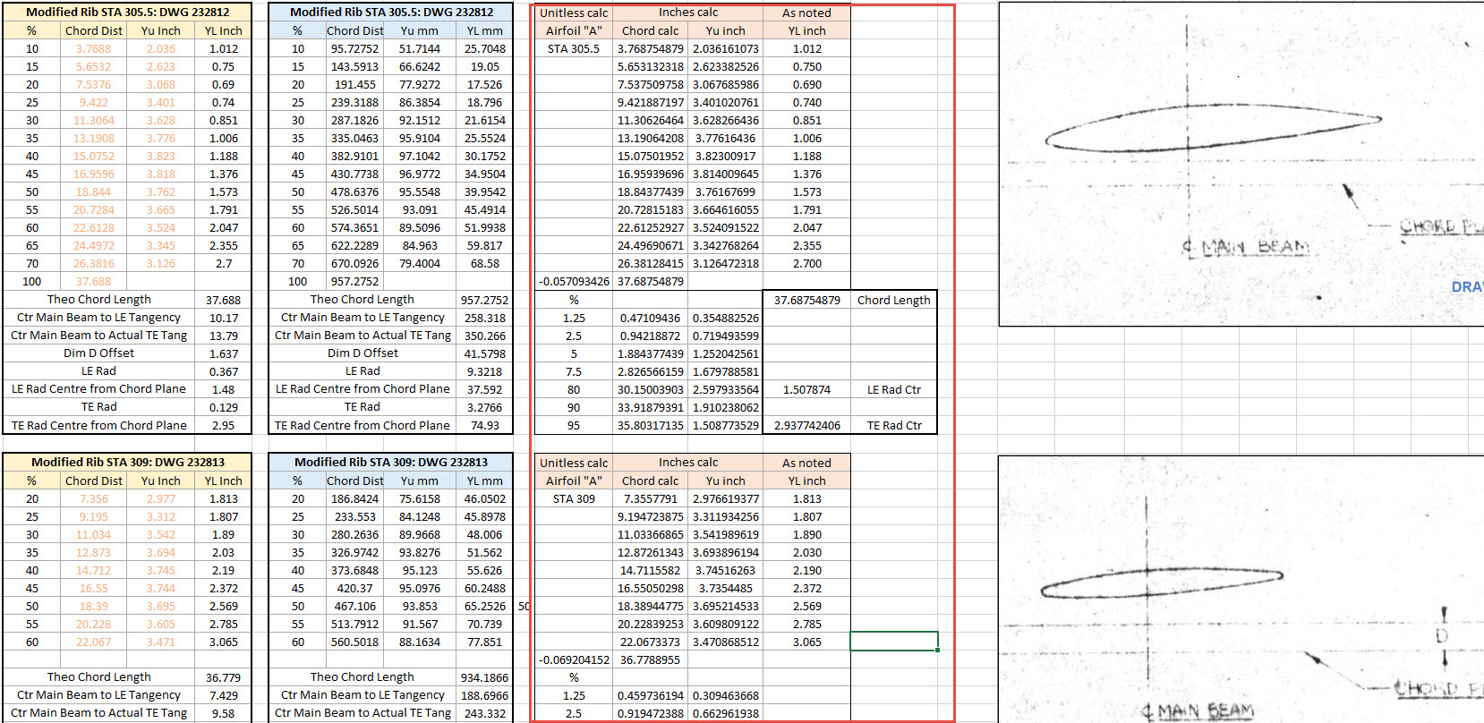
Accuracy is extremely important to ensure a good surface finish with no small deviations or folds. So I checked the coordinates of each profile mathematically and adjusted the dimensions accordingly for the top surface.
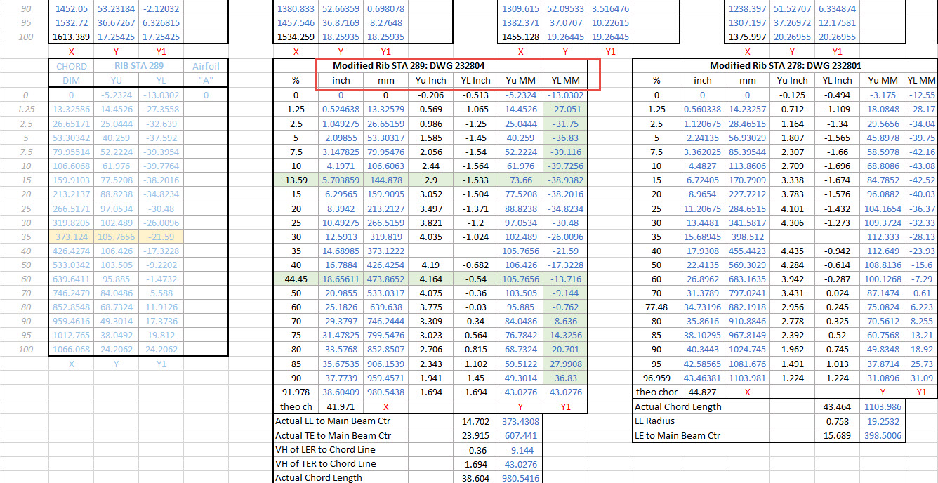
The rib profile at 1,2 and 3 was adjusted to the new coordinates for the top line only but making sure that the LE and TE were tangential to the mathematically generated curves shown in red. These end ribs are actually modified profiles according to the tabulated information on the Lockheed drawings…apparently, the profile at the wing tips is based on a NACA 4412 airfoil but when I generated a 4412 it did not match…I am not sure why but it is something that warrants further research. As I did not have the mathematical formulas or guidance on hand to check the lower profiles I accepted what information was contained in the tables…mind you I could have generated a line equation from this information in Excel. Incidentally, all the wing ribs were checked mathematically with the resulting dimensions used to generate the profiles throughout.
The first image shows a sample of the modified values at Rib station 289, highlighted in green alongside the normal profile on the left. The second image shows the explanation of how the main wing rib profiles were generated. All this information is included in the CAD/ordinate dataset. Also on the second image, you can see a typical rib profile extracted from the Lockheed drawings which shows the 0% chord is actually set back from the Leading Edge, which is most unusual. This created a few problems because now I had to determine from the CAD model the Actual Leading Edge before I could define the curved guide rails for generating the wing tip lofts.
This all may seem overkill and a lot more work than one would expect just to build a wing tip but the Inventor Loft command requires absolute precision when lofting with guide rails so it pays dividends to mathematically check everything where possible to ensure successful lofting. I shall update the CAD/Ordinate dataset over the next few days to include this new data.