Technote: 3D Printing-My Perspective

Technote: 3D Printing-My Perspective

Recently, I acquired the Elegoo Centauri printer, and I would like to share some details about my experiences using it for aviation projects. When I received this printer, it actually sat in its box for about a week, as I was not quite ready to deal with the vagaries of FDM printing until fate intervened. I was also swamped with updates to the Grumman Goose and FM2 ordinate studies alongside development of the P-47. I didn’t really have much time for anything else.

Then the unexpected happened: my computer suffered a catastrophic hard drive malfunction. I opted to send the hard drive to a specialist company for data recovery; though technically I could have done this myself, the data was too important. So, having time on my hands, I set up the Elegoo Centauri and did some 3D printing.

I have been using resin printers for a few years, but I have never tried FDM printers. I used to believe that resin printing was the ultimate form of 3D printing when it came to dimensional accuracy and surface finishes, which FDM printers couldn’t match. However, I now realise I was mistaken!

This Elegoo Centauri is, quite frankly, a really good printer, a bargain at less than £300.

As I had an old laptop, I was still able to access my email and online accounts, but running any substantial software was out of the question on an antiquated version of Windows. So what I did was send CAD files from my online backup to my son-in-law, and he would slice them for me and send me the G-code for printing. This was sufficient for me to get started and explore the vagaries of FDM printing. Later, of course, when I got my hard drive sorted and my computer back up and running, I was then in a position to address several questions from my first foray, and this is what I will share with you today.

P-39 Airacobra – Planes of Fame:

As many of you know, and as previously covered in various posts on this blog, I have been assisting Planes of Fame with their P-39 restoration project. Where possible, replacement parts are manufactured to the original material specification; however, in some areas, particularly the cockpit control units, it was decided to opt for 3d printing replica parts. This is a static restoration, so this is quite acceptable. Though I often wonder with the plethora of advanced printing materials, whether 3d printing could be an effective replacement for flight-worthy restorations.

One of the first parts I printed when I got my computer back in working order was the Exhaust Stacks. Previously, I have had a post already on this, but the reason why I decided to print this was to explore metallic finishing options and acceptable material thicknesses.

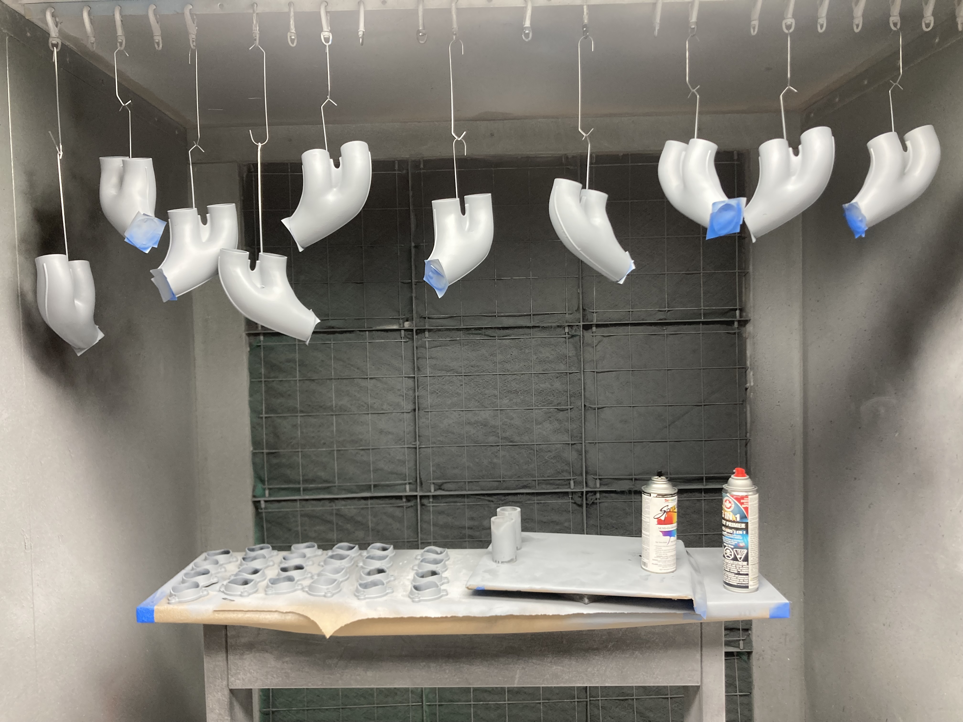
Planes of Fame has access to an industrial-grade 3D printing facility using engineering-grade filament, the results of which are shown in the second image above. I figured that there was no way I could replicate that level of quality on a budget printer, but surprisingly, the Elegoo Centauri did remarkably well just using PLA+.
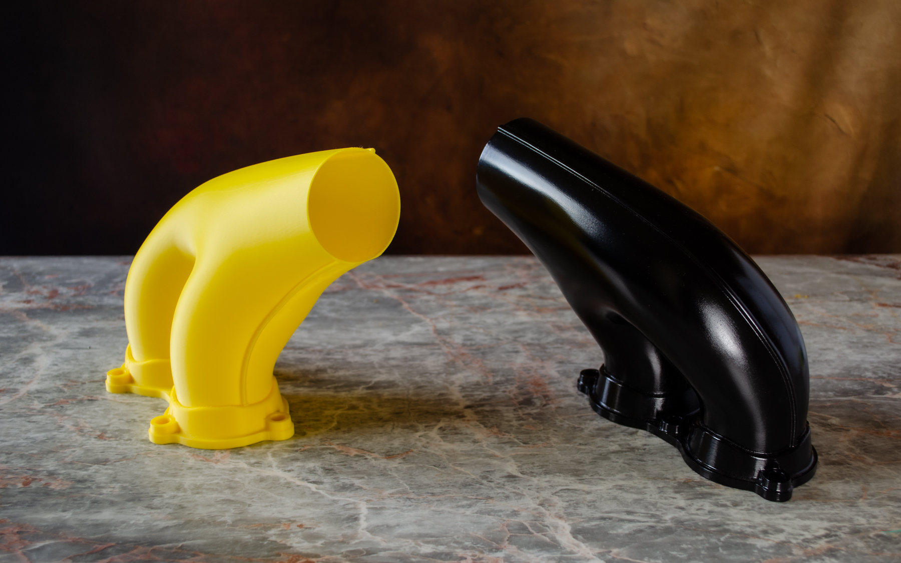
When I developed this CAD model, the exhaust wall thickness was set to 1mm…this was to make it easier for Planes of Fame to adjust the minimum wall thickness to suit the industrial printing preferences. I actually decided to initially print this at the 1mm wall thickness to see how well the Centauri handled thin walls. I was pleasantly surprised that, other than a few minor imperfections, the print came out really well. However, as this exercise was more about exploring metallic finishes, I decided to print it at 1.6mm wall thickness to give me some latitude for sanding. The black version in the first image shows the result of applying Filler Primer; 2 coats of sanding with 80, 120 and 320 grit sandpaper, and then applying 2 coats of black gloss. To achieve the metallic finish shown in the second image, I rubbed in graphite powder. There are several cosplay videos on YouTube showing how this was done on items like the Mandalorian helmet.

The surface should ideally be completed with a clear coat, but I don’t have any of that. The finish, I think, is quite dark and could be improved to be more aluminium-like if the paint were Gloss Grey instead of Gloss Black. I shared these details with Planes of Fame; I understand they may opt for the latter.

Custom Supports:

For the Exhaust stacks, I used the slicer Organic Tree supports, which were fine, but there was some stringing evident on the inside surface. I decided to explore options for custom supports instead to achieve better results. Again, working with a P-39 part, this time the pilot seat top support bracket. I should note that Planes of Fame has this same model; however, they will be making this from aluminium.

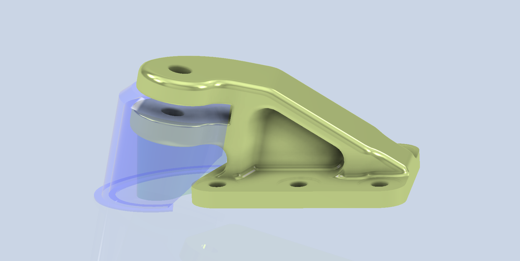
The first image shows the comparison between the slicer standard tree supports and using custom supports. Looking at the circular portion, the item on the left shows an irregular surface from the tree supports, whereas the version on the right shows a much more refined, consistent surface from using custom supports. The second image shows the custom supports created in CAD.

From my experimentation with generating custom supports that a gap of 0.24mm when printing at 0.12mm layer height works quite well. There is some consensus that one layer thickness would be an optimal gap, which may be applicable if the surface is planar to the base; however, in this instance, there is a small incline, and I find that 0.24 works well with the supports easy to remove.

I also did some experimentation with another model, completely unrelated to Aviation, and this was for my wind turbine project.
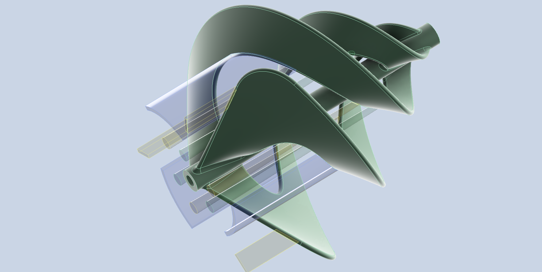
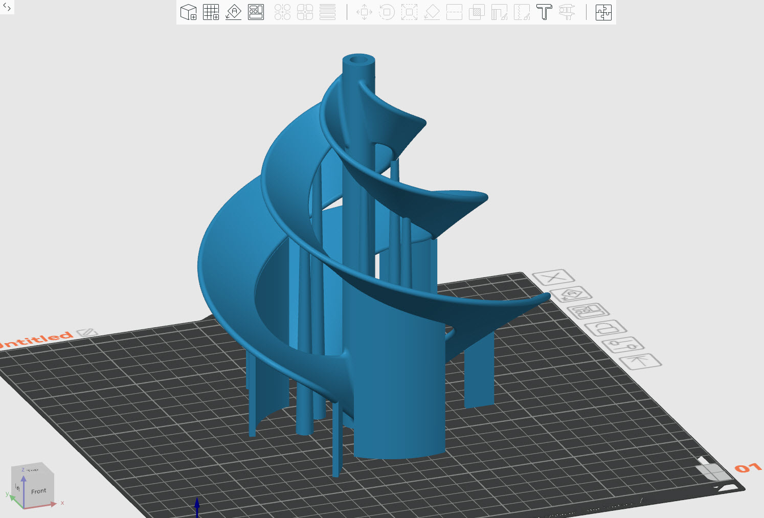
Supports are necessary when the threshold angle is less than 30 degrees. Additionally, I’ve included extra supports to enhance stability, as the model may flex during printing due to the thin blades. I often find that a combination of custom supports and standard tree supports works well on more complex models.

Minimum Wall Thickness:

I touched on this with the Exhaust Stacks, and though 1mm is the recommended minimum wall thickness for 3D FDM prints, you can go thinner. There is a setting in most slicers called “Spiral Vase” or similar. What this does is produce a print with a wall thickness equal to the nozzle diameter. I tried this with a surface model for the Vertical Stabiliser for the Grumman Goose at 1:10 scale, and it actually worked quite well.

The downside is that this setting ignores any internal ribs that may be in the model and only prints the outside wall. I imagine there may be some uses for this in aviation modelling, but to be honest, without internal rib supports, there is probably too much flex. I should note that layer adhesion remains good, and the surface finish is smooth.

I intend to explore workable solutions for achieving minimal wall thickness and thus reducing the weight of model RC aircraft. As my main line of work is compiling all the known key dimensional information for the various aircraft and presenting this information in a concise, accessible format and in CAD, I see this as a natural extension of these studies.

I already have several surface models (SU-31 and L23 Blanik) that can be easily scaled and adapted to produce accurate replicas for RC flight. The key to this is when scaling to then apply material thickness to the ribs, frames and surfaces that will be suitable for 3D printing whilst maintaining structural integrity with minimal weight. My current theory is that 2 x nozzle diameter for minimum wall thickness and 3 x minimal layer thickness may work.

My work on this issue is in the very early stages, and I will dedicate a specific post to this with my suggestions and samples of the end product.

Finally: Printing Dowels:

This is something I only ever did on my resin printer due to the possibility of snapping along the layer lines. However, there is a solution for successfully printing dowels on FDM printers. I tend to use dowels a lot for aligning individual parts of an assembly.

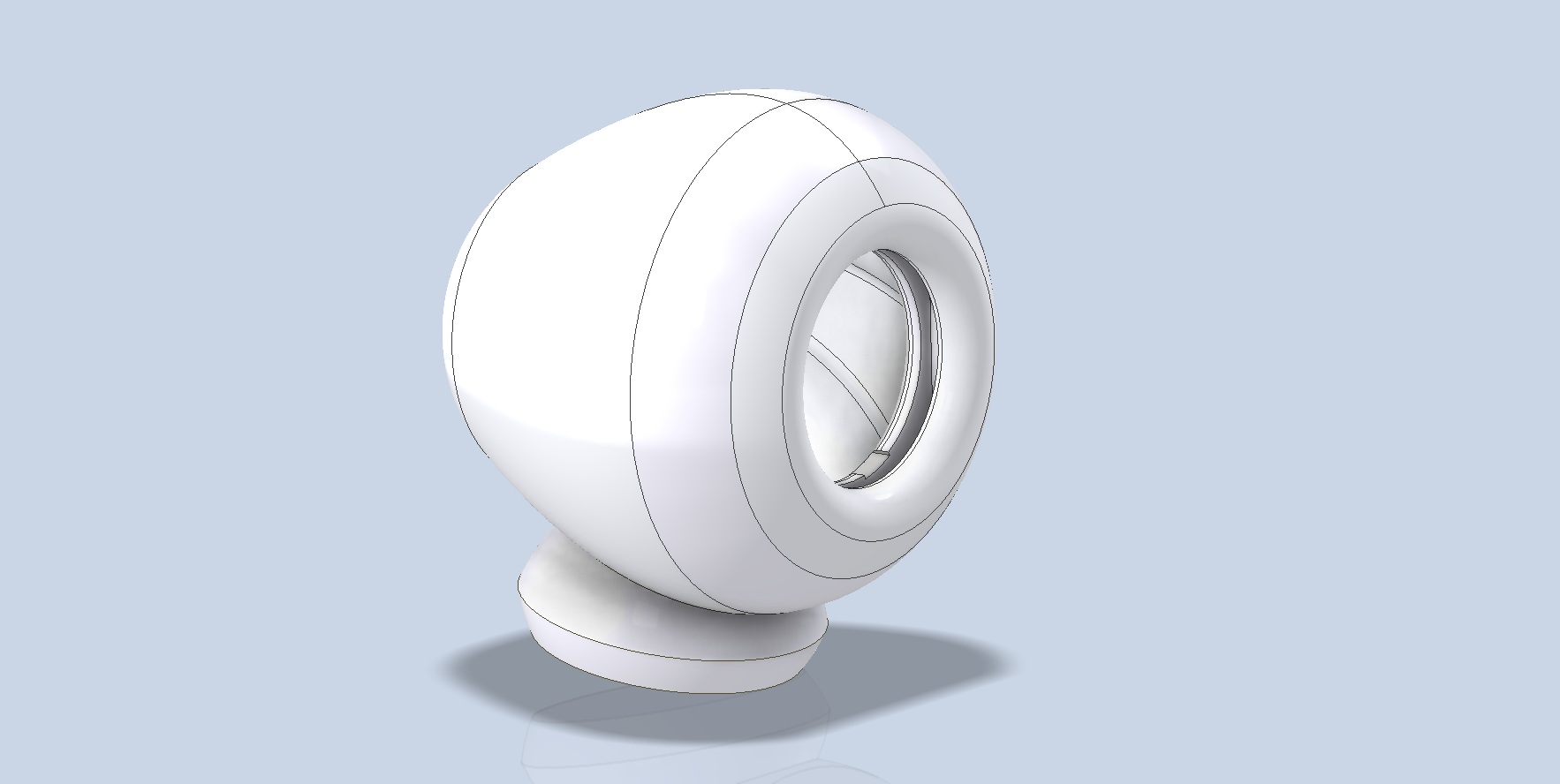
For my desktop speaker projects, the body parts are aligned using dowels. As you can see, the dowel has 3 flat sides which can then be laid flat on an FDM print bed to enable printing with layer lines longitudinal to the axis and thus preventing splitting.

Rendering the JB2 Using Autodesk Vred

Rendering the JB2 Using Autodesk Vred:

For quick renderings that are perfect for blog posts, I typically prefer KeyShot. It provides an intuitive workflow and a large library of environments and materials. However, the trial version has some limitations: you cannot save projects or export a rendered image, except as a screenshot. When I was recently asked to produce high-quality renders of the Republic JB2 for a museum display, I was uncertain about how to accomplish this.

These products are very expensive and far exceed my budget, so I urgently needed to find a solution. That’s when I discovered Autodesk VRED. I downloaded the software along with the accompanying asset library, and to my surprise, the trial version is fully functional. It allows me to save projects and create high-resolution renders, and it runs for 30 days.

Autodesk Vred retails at around $14000, which is extraordinarily expensive, but it is aimed primarily at the Automotive industry. Consequently, the product is packed full of features and limitless options on environments, materials, lighting and camera setups. It truly is a comprehensive and, to some degree, rather complex product, so there is a steep learning curve.

Undeterred, I set to work by reviewing tutorials, YouTube videos, and various online resources. Over the course of six days, I gained a deeper understanding of the nuances of VRED rendering. While I’m not an expert yet, the test renders started to come together, culminating in the images showcased below.
These images are not final, as I still need to work on the texture mapping and apply materials to some internal components. However, they demonstrate that it is possible to achieve satisfactory results in a relatively short time. Although the product has a steep learning curve, it encourages you to deepen your understanding of materials, textures, and lighting, which ultimately enhances your grasp of rendering processes.

I highly recommend that anyone interested in creating renders try Autodesk VRED. It offers the full functionality of a high-end rendering product, including the ability to save your projects and export high-resolution renders. The availability of a 30-day trial version is exceptional—Keyshot, take note!

I want to clarify that I have no affiliation with Autodesk, but when it comes to the accessibility of professional products, Autodesk is unparalleled. I have no problems recommending worthwhile products, like this one.

Preserving Memories: A Personal Journey Through 35mm Film

Preserving Memories: A Personal Journey Through 35mm Film

I haven’t posted in a while due to personal reasons. During this time, I’ve been browsing through my extensive film archives and reflecting on cherished memories. Alongside family and friends captured in many rolls of film, I also have a comprehensive collection of aircraft photographs spanning the last 40 years.

From sleek fighters and vintage prop planes to experimental designs and airshow spectacles, each frame tells a story of engineering, elegance, and airborne ambition. These images aren’t just pictures; they represent moments suspended in time, chronicling my lifelong fascination with aviation.

However, as the years pass, the urgency to preserve these images grows. Film curls, fades, and gathers dust. Scanning them digitally isn’t just about convenience—it’s about safeguarding history, honouring friends and family, and unlocking the full potential of each shot. Therefore, I decided to explore options for digitally scanning these libraries to preserve both personal memories and the history of aviation.

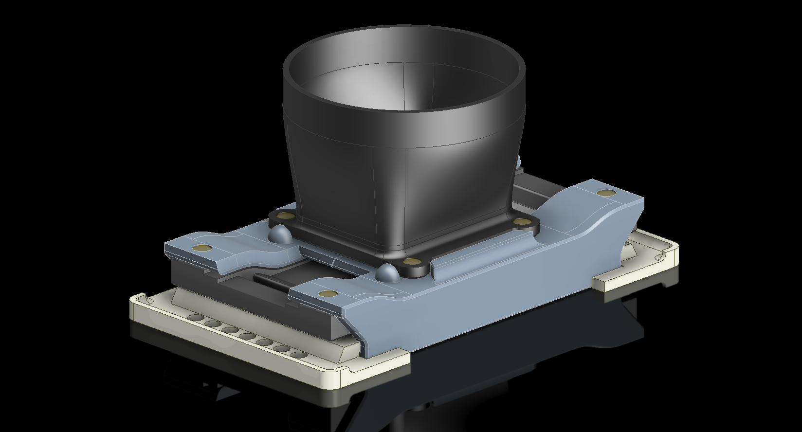
This led me to design a new type of 35mm film holder for digital scanning—one built not only for precision but also for passion. It’s a tool that respects the fragility of film while delivering the flatness, fidelity, and ease needed for high-quality digital scans.

From top left:

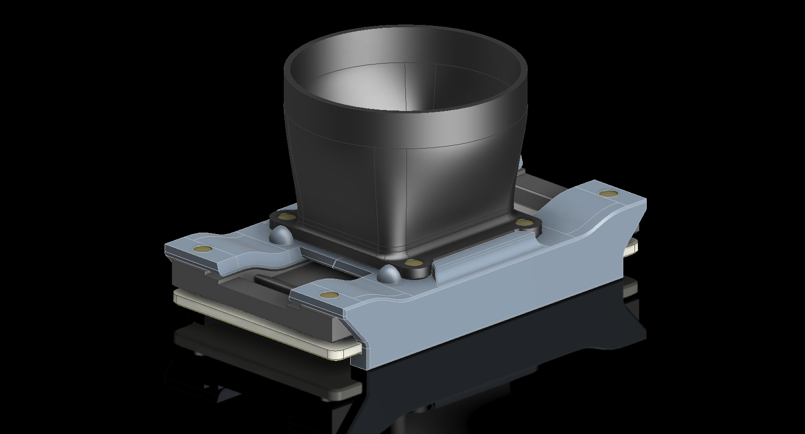
Film Holder, Film Holder with Hood, Film Holder with optional Diffuser, Film Holder with Spacers to fix location on CineStil Light box, 35mm Mounted Slides sit on top and held in place by magnetic Hood and finally a plan view of the complete assembly.

This Film Holder is designed to be Resin printed on the smallest build plate using the minimum amount of Resin. For the prototypes, I am using the Anycubic ABS-Like. It features an S-Curve guide track for the negative or slide film strips. This S-Curve is actually a mathematical matching of second-degree curves to ensure surface continuity instead of 2 tangent arcs. This S-Curve removes the physical curves typically found in film strips to ensure flatness at the viewing window. The S-curve is not a new innovation; in fact, I have examples of film holders for the rather old Epson 4870 flat-bed scanner, which has this feature, but only for 120 film.

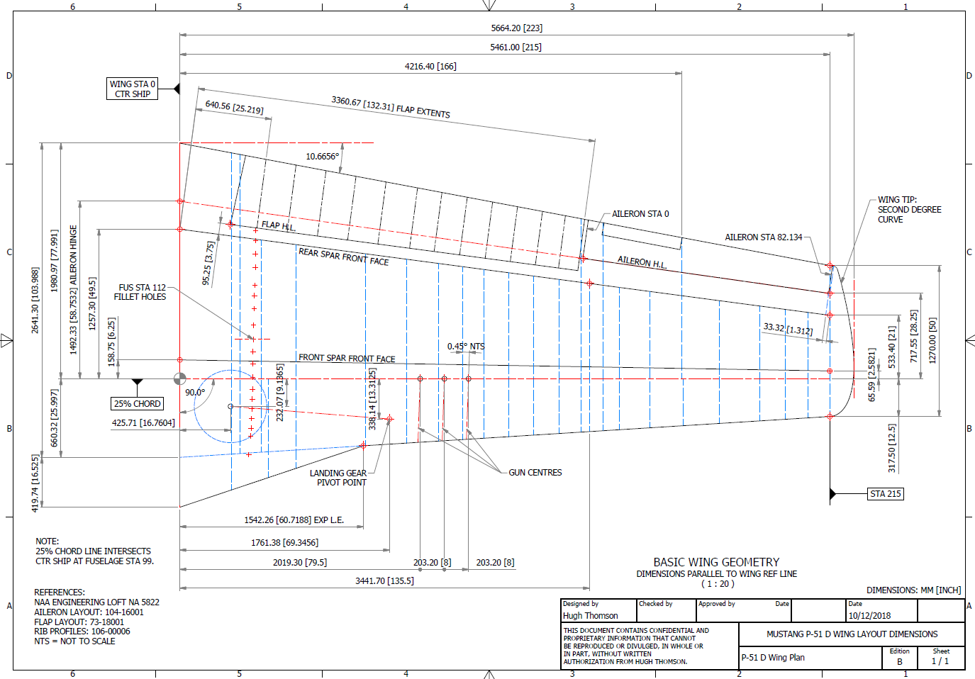
Incidentally, second-degree curves are essentially the building blocks that define the conic profiles of the P-51 Mustang.

I did some research on current commercially available options. Most off-the-shelf film holders suffer from a few persistent issues:

  • Curling and warping of negatives, especially older or heat-exposed strips
  • Inconsistent flatness, leading to soft scans and uneven focus
  • Enclosed loading slots that risk scratching or misalignment

As an aeronautical engineer and product redesign specialist, I saw an opportunity to rethink the film holder from the ground up—merging mechanical precision with modern usability at minimum cost.

I still have the copy stand to design and, of course, get my hands on a 1:1 macro lens. I currently have access to a friend’s camera and lens setup for a few days for testing, but in the long term, I need to try and raise funds for a more permanent camera and lens solution…currently looking at the Sony A7 III with 70mm Macro…a full frame, rather expensive, but worthwhile combination to achieve the optimum reproduction fidelity of the original.

I will update this post shortly with images of the final product…so watch this space!

For more information or inquiries, please drop me a line at: hughtechnotes@gmail.com

Update 17th Sept 2025: Some Renderings of the final product showing the configuration for mounted 35mm slides:

Footnote:

Of course I am still continuing my work on various aircraft ordinate studies, which will also now include the full DWG profiles for every listed fuselage frame and wing ribs. That is a lot more work than I intended with these packages, as the dimensional information is already listed in spreadsheets. I appreciate that not everyone has access to CAD and perhaps not the experience to develop profiles from spreadsheets; instead, they just want to get something made…so the information needs to be more accessible and usable.

Preserving Aviation History: Documenting Aircraft Dimensions


Aircraft Dimensional Data Documentation: Help Support This Initiative.

1. Project Title:

Aviation CAD TechNotes: Documenting Historical Aircraft Structures

2. Executive Summary:

This project aims to document and preserve dimensional data for historical aircraft, currently working on models such as the P-47, FM2, and Grumman Goose, alongside two glider projects. Utilizing archival blueprints—often of suboptimal quality—we employ precise digital reconstruction techniques to ensure the accuracy of aircraft structural data. The goal is to support restoration efforts, research, and educational initiatives in aviation history.

3. Objectives:

  • Digitally reconstruct and verify the dimensional data of historic aircraft.
  • Provide comprehensive documentation for restoration, museum displays, and aerospace research.
  • Develop methodologies for extracting accurate data from degraded blueprints.
  • Expand the available reference library for aviation researchers and engineers.

4. Significance & Impact:

  • Historical Preservation: Ensures that legacy aircraft remain accurately documented for future generations.
  • Educational Contribution: Supports aerospace research institutions and museums with validated technical data.
  • Technical Innovation: Implements advanced CAD techniques to refine aviation blueprint analysis.

5. Methodology:

  • Collection and analysis of historical blueprints and microfilm archives.
  • Use of CAD software to recreate accurate aircraft structures.
  • Cross-referencing archival data with existing dimensional records.
  • Collaboration with restoration experts to validate findings.

6. Challenges & Solutions:

  • Suboptimal Blueprint Quality: Implement specialized image enhancement and measurement techniques.
  • Funding Limitations: Seek partnerships with aviation museums, historical organizations, and aerospace institutions.
  • Data Validation: Engage with experts to cross-check reconstructed aircraft dimensions.

7. Funding Request & Justification:

The project has been independently funded to date, but rising operational costs present financial challenges. Support is requested to sustain ongoing research, enhance documentation quality, and facilitate broader distribution to historical and aviation institutions.

8. Potential Collaborations & Sponsorships:

  • Aviation Museums: Partnerships for data preservation and restoration projects.
  • Educational Institutions: Opportunities for research integration and student engagement.
  • Aerospace Industry Experts: Validation and application of documented data.
  • Fellow Enthusiasts and Donors: Acknowledge contributions, engage in peer-to-peer discussion and provide technical support where applicable.

9. Conclusion:

This initiative offers a critical contribution to aviation history by preserving precise structural data of historical aircraft. With adequate funding and institutional partnerships, the project will continue advancing research and documentation efforts for aviation scholars and engineers.

—————————————————————————————————

Contact Hugh Thomson via email: hughtechnotes@gmail.com.

P-39 Fuel Tank Covers and Filler Cap

P-39 Fuel Tank Covers and Filler Cap

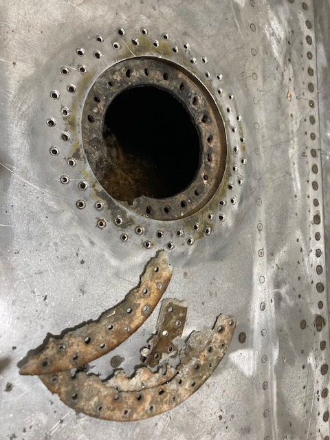
The P-39 restoration project is still very much a work-in-progress. The latest addition to the project is the Fuel Tank Covers and Filler Cap. When the existing components were removed there were visible signs of corrosion so it was decided to replace the inner mounting rings as well as the covers/caps.

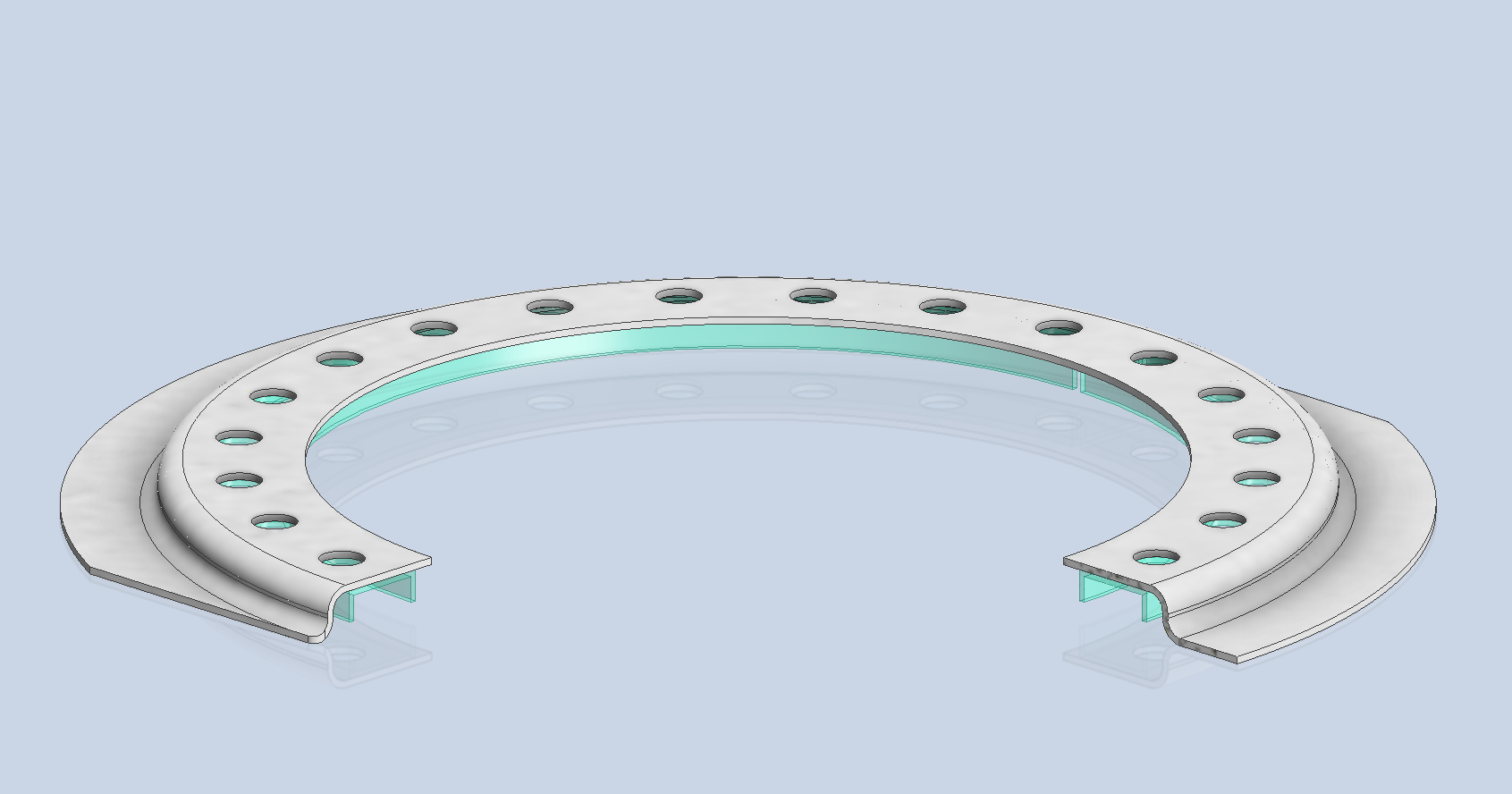
Each cap assembly consists of an inner mounting ring, a Goodyear-type sealing ring, and cover plates. It is important to consider the varying thicknesses of the sheet metal at each location, as this can lead to slight differences in the profiles of the mounting rings. Typically, when we develop these types of parts, we mark the holes in situ based on existing hole patterns to ensure a proper fit. This is usually done because the holes are evenly spaced between two known locations, which can vary during manufacturing. However, for these covers and caps, we have precise knowledge of the hole locations, allowing us to ensure an accurate match.
The flush rivets used throughout are the 35R1 Bell standard, featuring a 120-degree countersink designed for thin sheet materials. An equivalent Boeing standard for this type of rivet is also available. In the assembly drawings, I have spaced the components apart to enhance clarity. I should note that the drawings shown are still a work in progress.

Update: Ready for issue:

This is the final assembly, typical for the fuel tank covers and caps.

The lower ring features an Elastic Stop Nut Gang Channel. It is presumed that this channel was designed according to Bell standards when it was constructed. I have examined various companies that supply similar Gang Channels; however, the hole centers in their standard components differ slightly from our specifications. I suspect that we will need to have a bespoke fabricated item to meet our requirements.

It may be possible to purchase Elastic Stop Nuts and retaining springs from companies like Howmet Aerospace and create a channel to match the design in the second image below. I will provide an update later on how we will proceed.

I will also soon be able to provide you with more information about the P-39 restoration and a gallery of images showcasing the latest work.

F4F/FM2 CAD Updates

F4F/FM2 CAD Updates

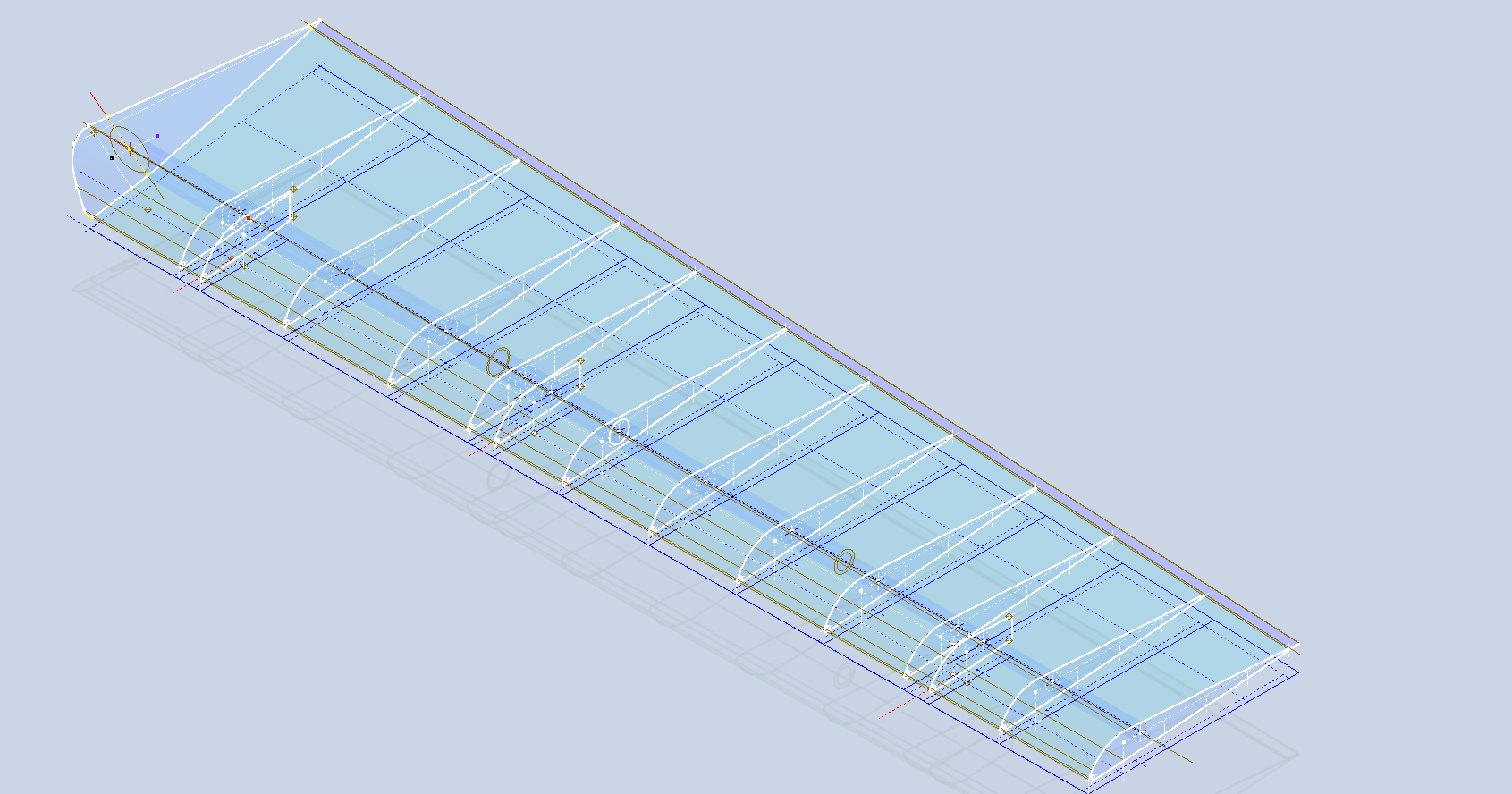
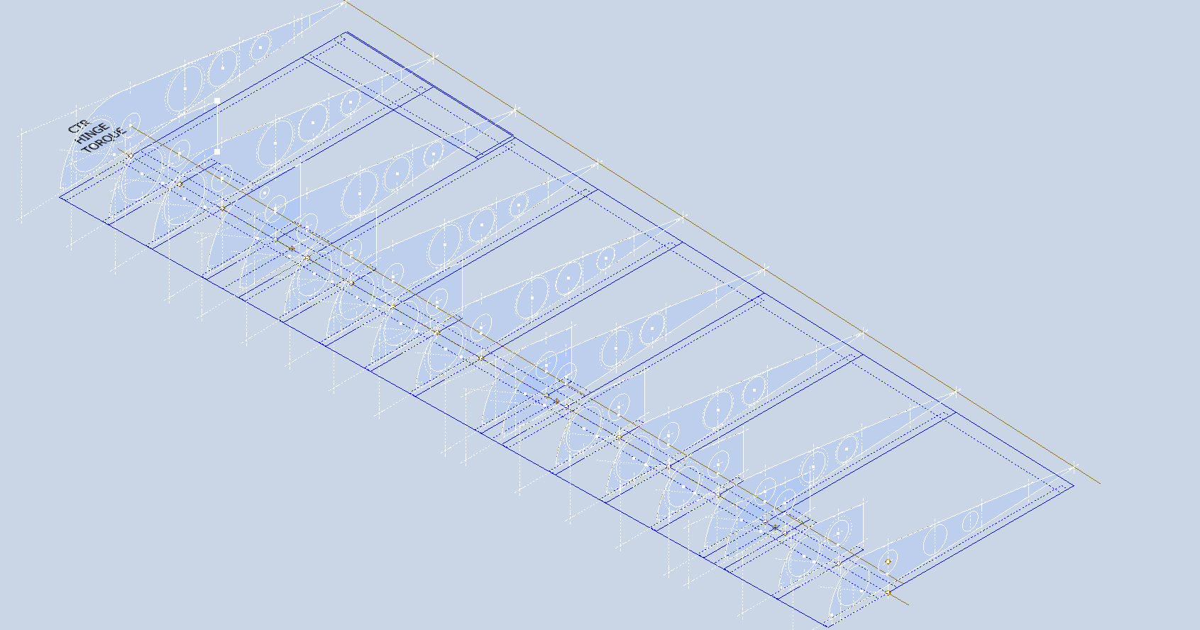
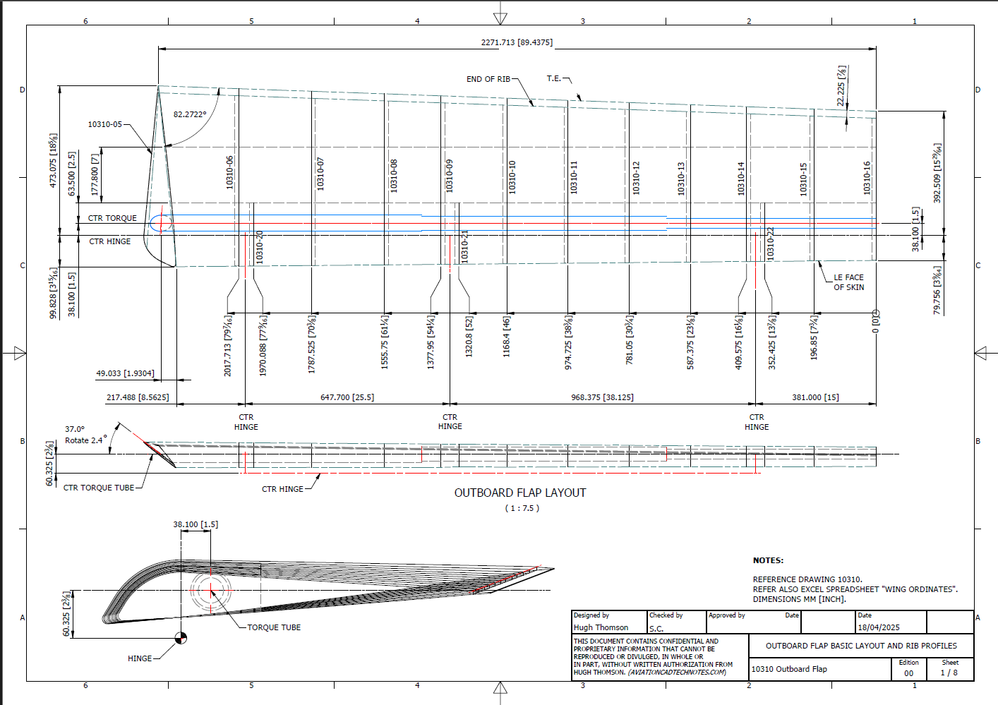
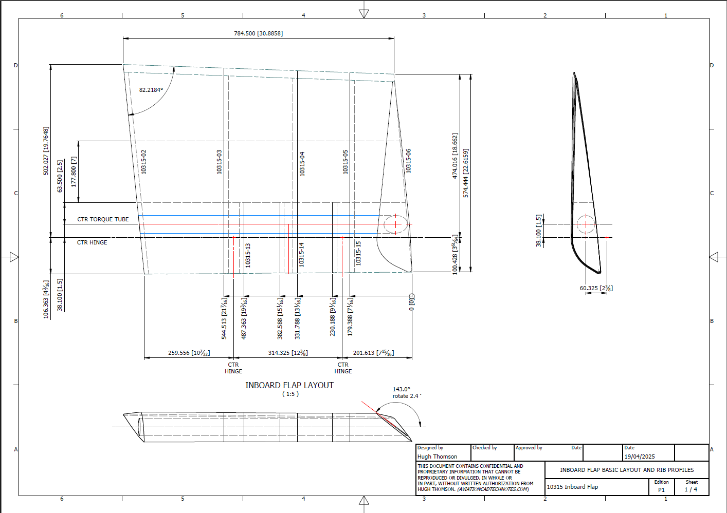
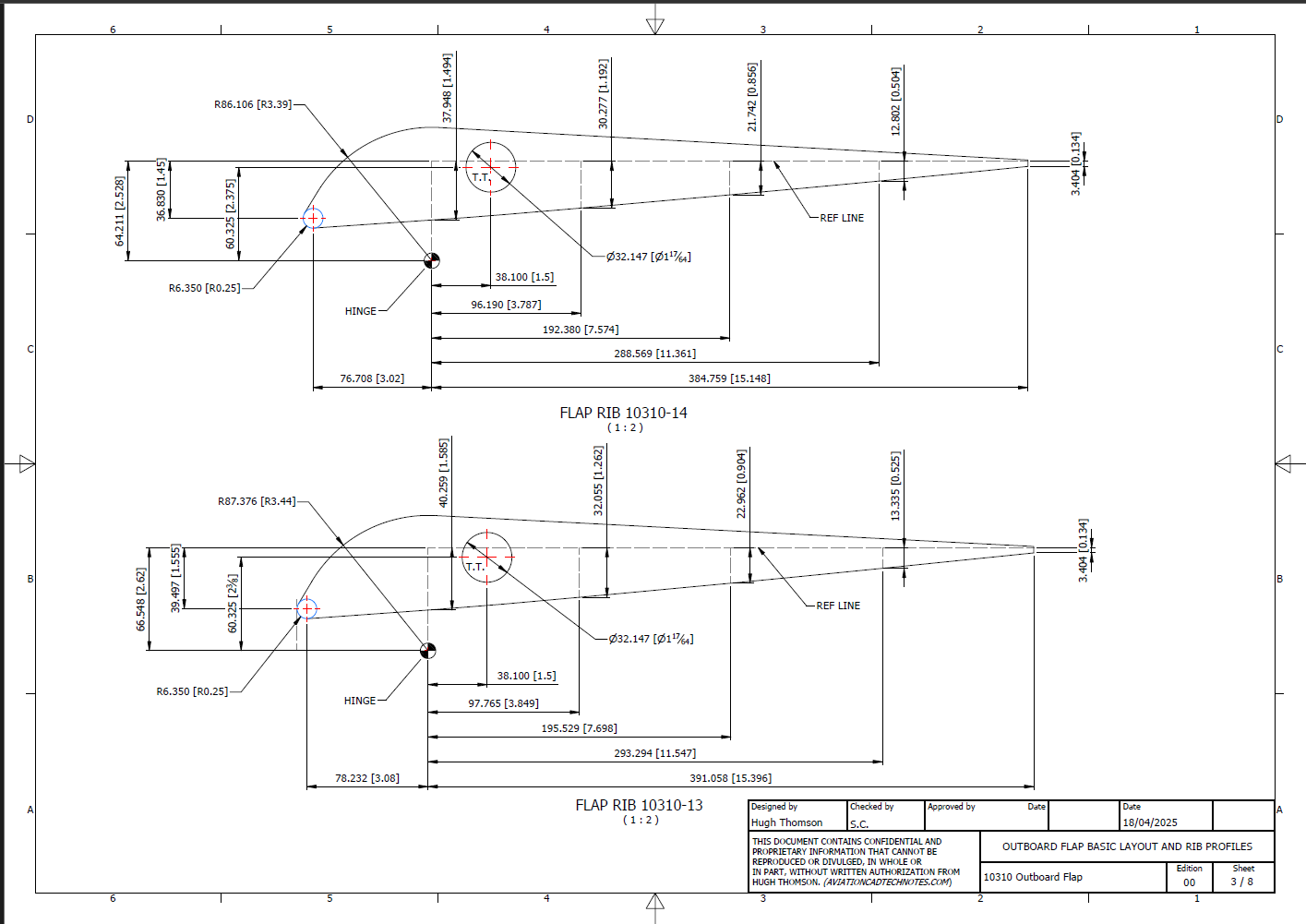
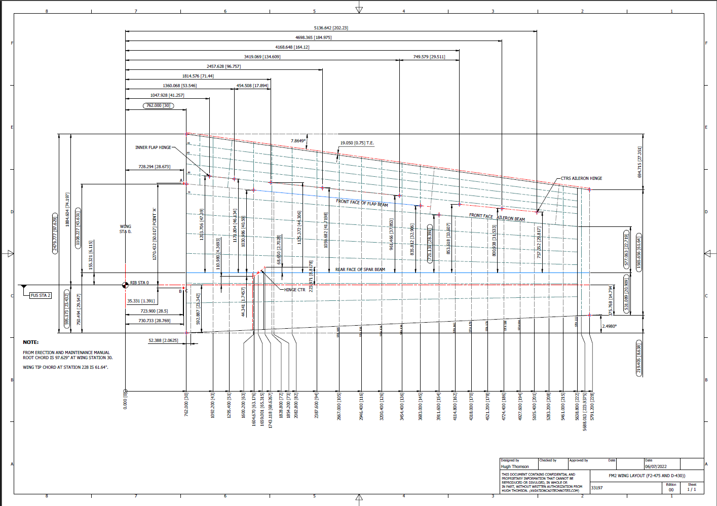
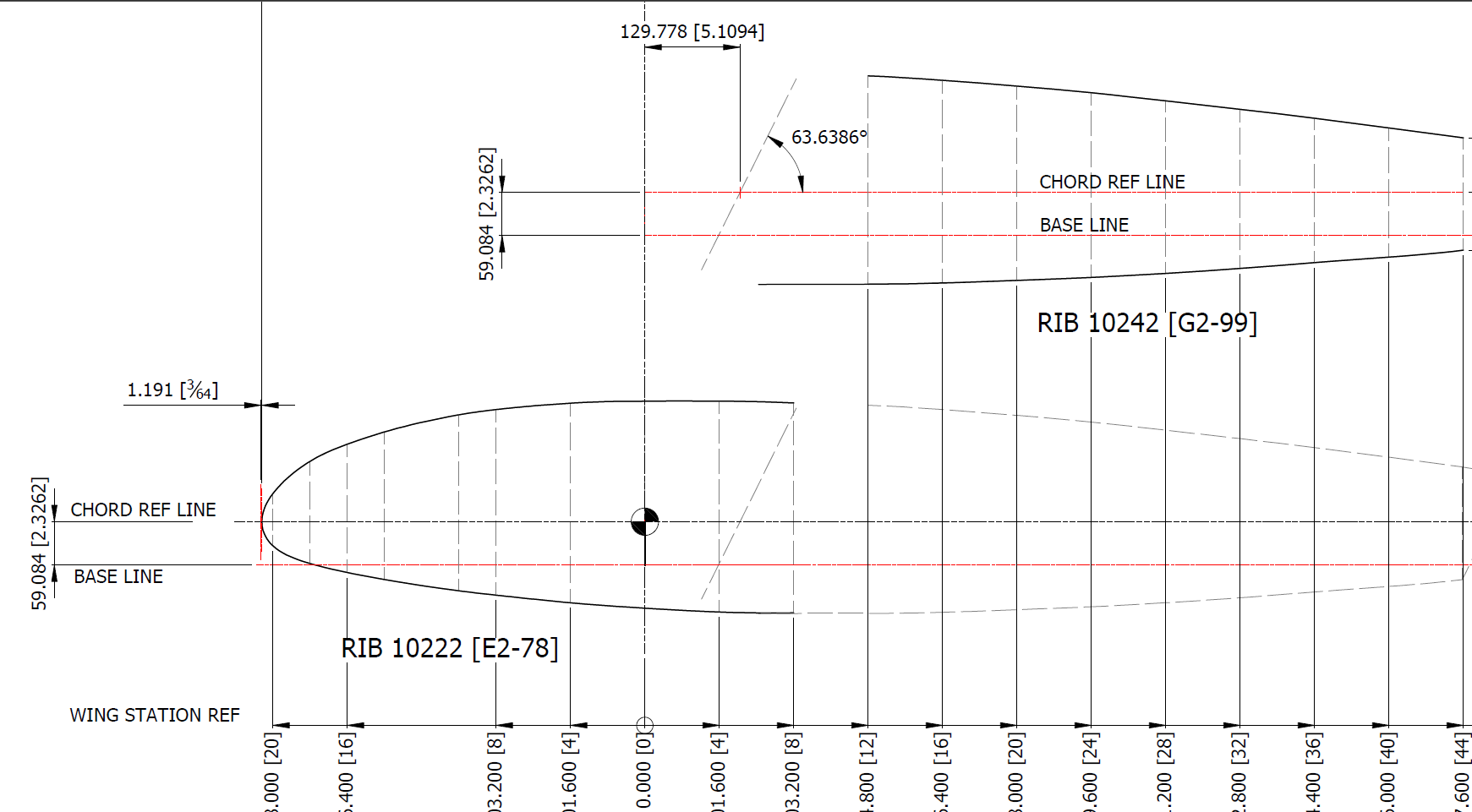
I have added new updates to the FM2 CAD/Ordinate dataset, completing assemblies for the Aileron, Outboard Flap, and Inboard Flap. In addition to the 3D CAD models, we have the fully dimensioned 2D drawings defining the profiles for all ribs.

Wing Layout and Rib Profiles:

The wing ribs comprise 3 separate rib profiles for the Leading edge, Mid-section, and Trailing edge. The detailed drawings show the complete profile and the individual component profiles separately. This will identify the blueprint drawing number in each case and the related blueprint scan file name.

Every drawing will be available as a full size Autocad DWG. All rib profile offsets are listed in a comprehensive Excel spreadsheet.

Unlock Precision with Aircraft CAD/Ordinate Data

Unlock Precision with Aircraft CAD/Ordinate Data:

The CAD/Ordinate datasets are designed to offer detailed documentation of the dimensional information pertaining to the core profiles of various aircraft components. This includes elements such as fuselage bulkheads, cowls, vertical stabilizers, horizontal stabilizers, wings, rudders, flaps, ailerons, and elevators. Essentially, these datasets provide all the dimensional information needed to develop the main profiles for aircraft construction.

The research studies were conducted to fill in important gaps in information and to clarify unclear details. Often, data on blueprints can be difficult to read, making it necessary to record and analyze the bulkhead or rib profiles in CAD. This process helps accurately determine the correct dimensions.

The examples of ordinate dimensions above are not necessarily the worst; in fact, there are truly poor examples that exist. To tackle these issues, we should start by recording the known dimensions in Excel and making educated guesses about the worst examples. Next, we can create each profile in CAD. This CAD profile will give us a clear visual representation of any anomalies in the curvature, which can be further analyzed through curvature analysis to identify low and high spots. This process is done for every rib and bulkhead profile where we have ordinate dimensions.

The spreadsheets above are typical examples of CAD/Ordinate datasets. The first spreadsheet contains the Ordinate record for the P-38, while the second one features the Aileron sheet for the FM2. You may notice a Linear Regression analysis table included in the FM2 sheet. Initially, determining the individual profiles of the ribs or bulkheads is just the first step; we now need to assess the assembly of all these components and check for proper alignment.

Each drawn sketch profile in CAD will serve as the border for containing a surface patch.

There are two primary reasons for doing this. First, it provides us with a plane that can be converted into a working surface, which can be utilized in any CAD product. Secondly, it provides us with a tangible element that we use to check assembly cross sections at key locations for alignment checks.

For example, consider the wing of the FM2. The wing assembly has been converted into a part file, and cross-section sketches were created at various chord locations: 30%, 60%, 70%, and 80%. Each sketch utilized the “Project Cut Edges” function to generate a cross-section of each rib. As shown in the second image, the array of lines representing the rib cross-sections provides a visual aid to identify high and low spots on the wing assembly. By creating a surface plane for each rib, we were able to generate these cross sections effectively. There were a few high and low points, which were double-checked and rectified.

If we require additional verification and strive for precision, we could use Excel’s Linear Regression to generate the coordinates for a Best Fit Line and make adjustments as needed. However, this approach may be excessive since our primary goal is to clarify the original blueprint data and apply it to identify appropriate rib and bulkhead profiles within acceptable parameters.

We can also use Linear Regression to give us an overview of how the ordinate profiles align with one another and to identify any discrepancies. Typically, acceptable parameters are within +/- 0.01 inches (or 0.254 mm), as specified by the dimensions on the blueprints, which usually only provide accuracy to two decimal places. Sometimes, as was the case with the P-51 and P-38, we had key design parameters that allowed us to calculate the exact profiles for each wing.

Validating dimensional data is crucial because the actual wing construction may not always match the accepted specifications. The design specifications for the FM2 call for a NACA 23015 airfoil at the root and a NACA 23009 airfoil at the tip. You might be surprised to learn that the NACA 23009 is a modified version of the standard 23009. Nothing is therefore assumed or taken for granted.

The CAD/Ordinate datasets are the result of extensive and thorough research and analysis, often taking many months of work, sometimes around the clock. These spreadsheets include every known ordinate dimension for various aircraft, gathered not only from blueprints but also from manuals, reports, and even correspondence. The CAD/Ordinate packages also include various 3D CAD models in various formats, including 3D DWG and fully dimensioned 2D DWG. All documents provided are fully editable so you can adapt the information to your work processes.

For more details on using the Ordinate spreadsheet data for your own CAD systems, see my earlier post here: Ordinate Overview

With over 45 years of experience in structural and mechanical engineering, my expertise influences everything I do.

In summary, the purpose of the CAD/ordinate datasets is the result of intensive work and research to provide the user with correct usable data that can be utilized in any CAD system.

When you buy CAD/Ordinate datasets and Blueprint collections from me, you support my ongoing research to provide the most comprehensive and probably the most accurate dimensional information about various aircraft. This blog and my research work would not be possible without your support.

Goose Bumps!

Goose Bumps!

The Grumman Goose project is both challenging and frustrating; it is definitely not a straightforward aircraft to work on. I have primarily focused on updating the empennage, which includes the vertical stabilizer, horizontal stabilizer, rudder, and elevator. During the development of the ordinate study, I observed discrepancies in the documented locations of various components. Let me explain what I mean.

Upon reviewing the CAD drawings on the left and comparing them with the Maintenance Manual diagram, I noticed that the level of the ribs varies by 1/16 of an inch. This discrepancy caused me immediate concern, and I began to wonder where I might have misinterpreted the Grumman drawing data. Therefore, I felt it was necessary to review and verify the information.

Initially, we do not have any reference location information on the Rudder Layout drawing. Normally, you would expect reference dimensions to the fuselage centerline or a fuselage station reference, but there are none. We do, though, have locations of the Hinges on other drawings for the Station bulkheads and Fin layout which in turn will help derive location information for the Rudder.

The first image above is the bulkhead layout at Station 36, which specifies the centre of the hinges 1, 2, 3, and 4 relative to the Fuselage Ref Line.. The second image is the bulkhead at Station 33, which shows the dimension of 65 13/16″ to the top of the Lower Rib on the Vertical stabilizer Fin.

I am looking to verify the dimensions and locations of the rudder ribs and hinges in relation to the Fuselage Reference Line. To accomplish this, we will start with the information we have and determine what additional information we need. The first image confirms that the CAD drawings for the rudder accurately depict the positions of the hinges. The second drawing further supports this; the “Top of Rib” location refers to the lower rib of the fin which includes the locations of the hinge centers. At this point, we have established the correct locations of the rudder hinges from two different sources.

Having determined the hinge locations, we know that the ribs for the rudder are offset by 5/8″ on either side of those locations, which allows us to derive the final levels noted on the Rudder Layout CAD drawing. Does this mean that the Grumman drawings, and therefore the CAD drawings, are correct while the manuals are incorrect? Yes and No…let me explain…

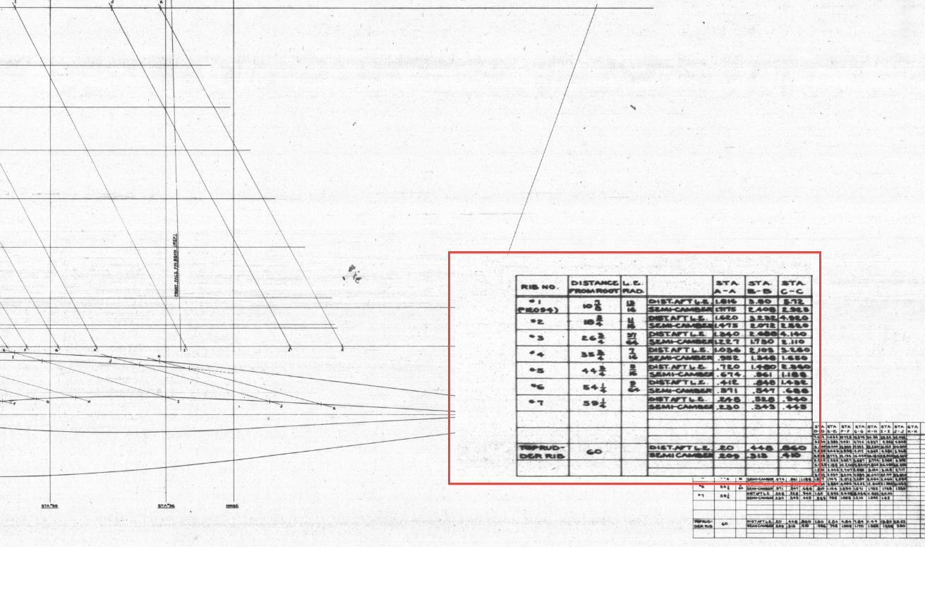
The first image is the Lines Diagram for the Vertical Stabilizer Fin Ribs. In the Table of Offsets, you will notice a list of dimensions from the “Root,” with the first rib specified at 10 7/8 inches. If we overlay these dimensions onto the CAD drawing, we observe a 1/16-inch discrepancy to the top of the first rib. However, all other sources, including those mentioned above and additional references not listed, such as the fuselage Lines layout, indicate that the top of the rib is correctly positioned in the CAD model (second image), contradicting the information provided in this Table of Offsets.

So what is going on?

We should take into account the revision history of the Grumman Goose development. If you examine their drawings, you’ll notice that they have made numerous revisions, some of which are labeled with letters as late in the alphabet as “R.” That indicates a significant number of changes.

I believe that various details have changed over the year, with the more prominent aspects being updated while the less prominent drawings remain unchanged. Regarding the manuals, it seems they were created early in the project, and it may have been considered too labor-intensive to update the level references. This aircraft is quite complex, and I can only imagine the effort involved in both its development and the ongoing updates to its design.

Whenever a small anomaly becomes apparent, I will make an effort to gather information from other drawings to verify the final result. This is one reason why these Odinate studies take so much time; it is crucial to ensure that the final study represents the most accurate dataset possible. If I were building a Grumman Goose replica, I would be using my datasets.

Progress Update 18th March:

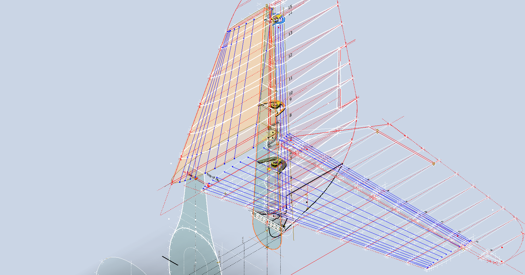
A few screen shots showing the latest updates to the JRF Goose. The wing has been completely rebuilt with all dimensions verified.

Overview Ordinate Dimensional Studies

Overview Ordinate Dimensional Studies:

On the CAD/Blueprint resource page, I have compiled a list of Ordinate Dimensional studies for various aircraft. The purpose of these studies is to gather all known dimensional information in a format that can be easily transferred to any CAD system. Additionally, they serve as a dimensional check to verify the designer’s intent and assess the accuracy of data from different resources, including blueprints, manuals, and correspondence.

Let me give you an example:

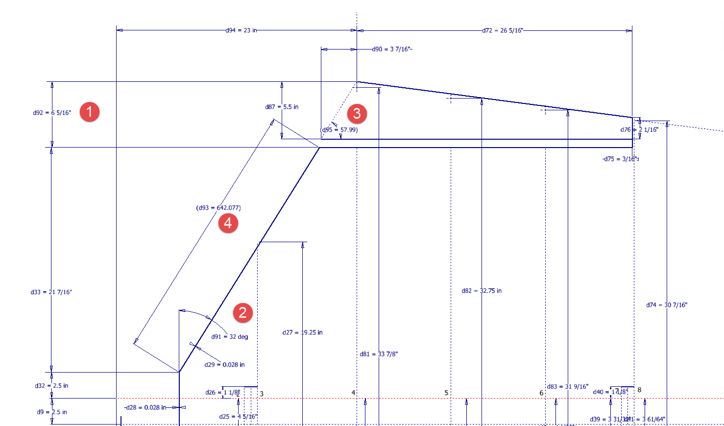
I am currently updating the CAD/ordinate dataset for the Grumman Goose and have already identified a few anomalies in the empennage. This document includes the layout study for the elevator, and you will notice that, based on the blueprint dimensions, the trim tab is incorrectly positioned.

At first glance, it may seem that the dimension labeled “1” is incorrect, as it appears to be the catalyst that causes the trim tab to go out of alignment. However, when we consider the length of the diagonal line labeled “4,” which measures 642.07 mm (25.27 inches), we find a discrepancy with the blueprint that specifies this dimension as 25 inches. Additionally, this measurement does not align with the chord dimension for the rib labeled “2.” As it stands, the angle of the sloping line appears to match at 32 degrees for both the trim tab and the elevator.

This type of issue frequently arises when working from blueprints for any aircraft project. To address it, further research is required, which will involve cross-referencing all part and sub-assembly blueprints in the affected area, reviewing general arrangement layouts, and consulting relevant manuals. It is essential to understand the design intent in order to develop the most likely solution. I have even extracted key information from correspondence that was important for the P-51 Mustang.

Small dimensional discrepancies are common in these projects, not only due to converting inch dimensions to millimeters but also because of typographical errors on the blueprints themselves.

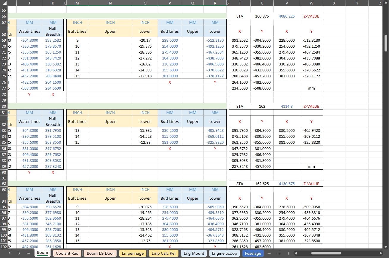
The screenshots of the Ordinate spreadsheets display the dimensional information for the Horizontal Stabilizer and the Rudder. Several dimensions are highlighted in red, indicating errors on the blueprints that have been corrected. The dimensions marked in gray represent the measured dimensions from the CAD model. This discrepancy arises from the inherent accuracy of the specified dimensions, which may only be precise to 1/32″. As a result, minor deviations can occur during the CAD development process. Understanding these differences requires careful consideration of all key layout dimensions and material thicknesses, as they all influence the final derived dimensions. Nothing is taken for granted.

The CAD/Ordinate datasets compile all known dimensional information from various thoroughly researched sources, providing a comprehensive collection of data. This data is presented in editable spreadsheets, fully dimensioned drawings, and 2D/3D CAD drawings and models.

Elevator Layout Solution:

I have identified a solution regarding the layout dimensions. The dimension labeled as “1” is incorrect, but it is not the primary issue. Firstly, the Trim Tab has its own drawing #12530, which indicates that the overall length of the tab is 28.75″. This measurement is incorrect; it should be 29.75″. Additionally, other dimensions are also contributing factors.

In the bottom left corner, we find the specifications for the Hinge and Torque Tube, where two dimensions are marked with a tilde underscore to indicate that they are approximate. Generally, approximate dimensions are expected to be close to the actual measurements; however, that is not the case here. By adjusting the overall length of the Trim Tab along with modifying the approximate dimensions at the hinge torque, and also ensuring proper alignment with the known trailing edge, I have arrived at a workable and accurate solution.

Tech Tip: Using the Ordinate Spreadsheets:

I often get asked this and I have written about using the Ordinate spreadsheets before. Bumping it up to a more recent post, this one; I thought I would share a quick tip.

The Ordinate data spreadsheet is on the left, while the other is an empty spreadsheet that I use to paste data for a specific frame or rib that the CAD system can access. The empty spreadsheet just sits on my desktop, which makes it accessible.

Generally, the format of the data table is set out according to the original resource, which makes it easier to cross reference and check. This is not entirely ideal for CAD access as the X, Y coordinates are in rows and not in columns. The fix for that is easy, copy the data from the spreadsheet as required, select Paste Special in the destination spreadsheet making sure to select the “Values and Formats” and the “Transpose” options. The former ensures the data format remains the same and the purpose of the Transpose function is to convert data rows to columns. This gives us the data in X, Y columns ready for insert into the CAD system.

Note the “inch” header…I am using a millimetre template in my CAD system so I have to specify the unit of measure when I select from the first table. By the way, there is a second table that has all those values converted to millimeter anyway, so we could easily use that…in this case, you would not require a header row.

In other datasets, I have developed additional data tables in the spreadsheet, where I have transposed columns for the X, Y, and Z coordinates, such as those for the P-39.

I receive a lot of feedback from users about the spreadsheets, specifically regarding the time they save on projects since they do not have to manually input data themselves.

Technote: P-39 Door Handle CAD Solution

Technote: P-39 Door Handle CAD Solution:

This little part at first glance seems fairly straightforward, but there are a few caveats.

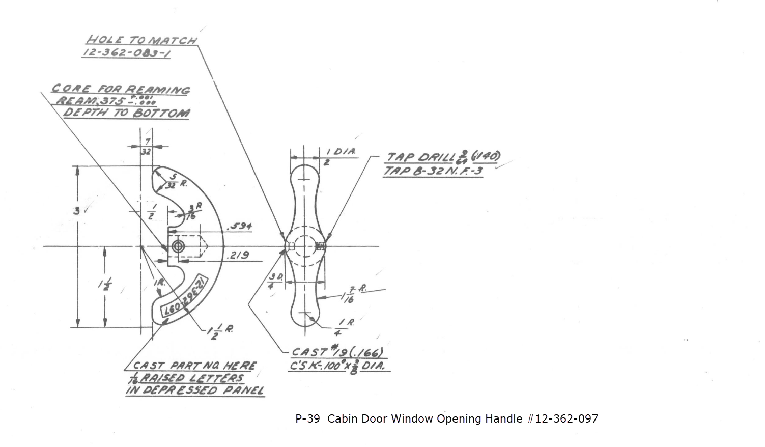
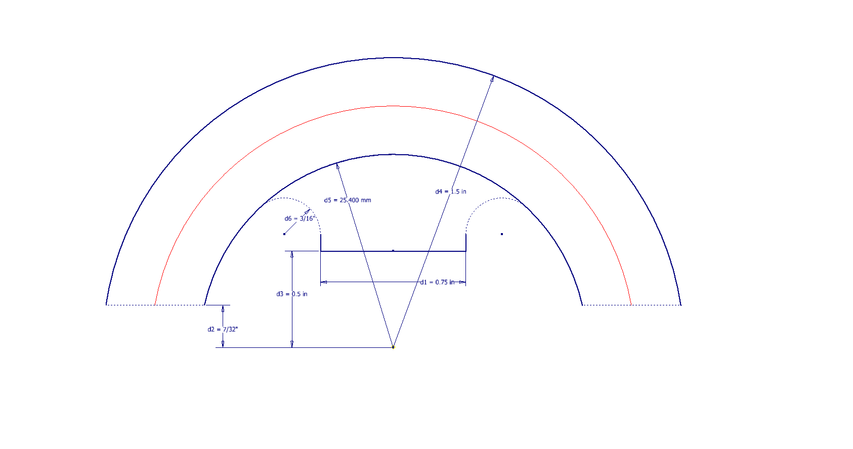
It has been a while since I specifically wrote a CAD solution Technote, and this seemed to be an ideal subject for surface modeling and 3D sketching. The dimensions define the outline for the front view, which is fine, and the plan view, which details a thinning of the handle cross section.

The thinning of the handle occurs in a specific plane as indicated in the plan view, while the front view maintains a consistent full depth diameter. Before diving into the modeling process, it’s important to pause and consider how to approach this design. Typically, my first step involves sketching out what is already known, which helps clarify the information we still need to gather. This initial sketching phase is crucial for laying the groundwork for an effective modeling strategy.

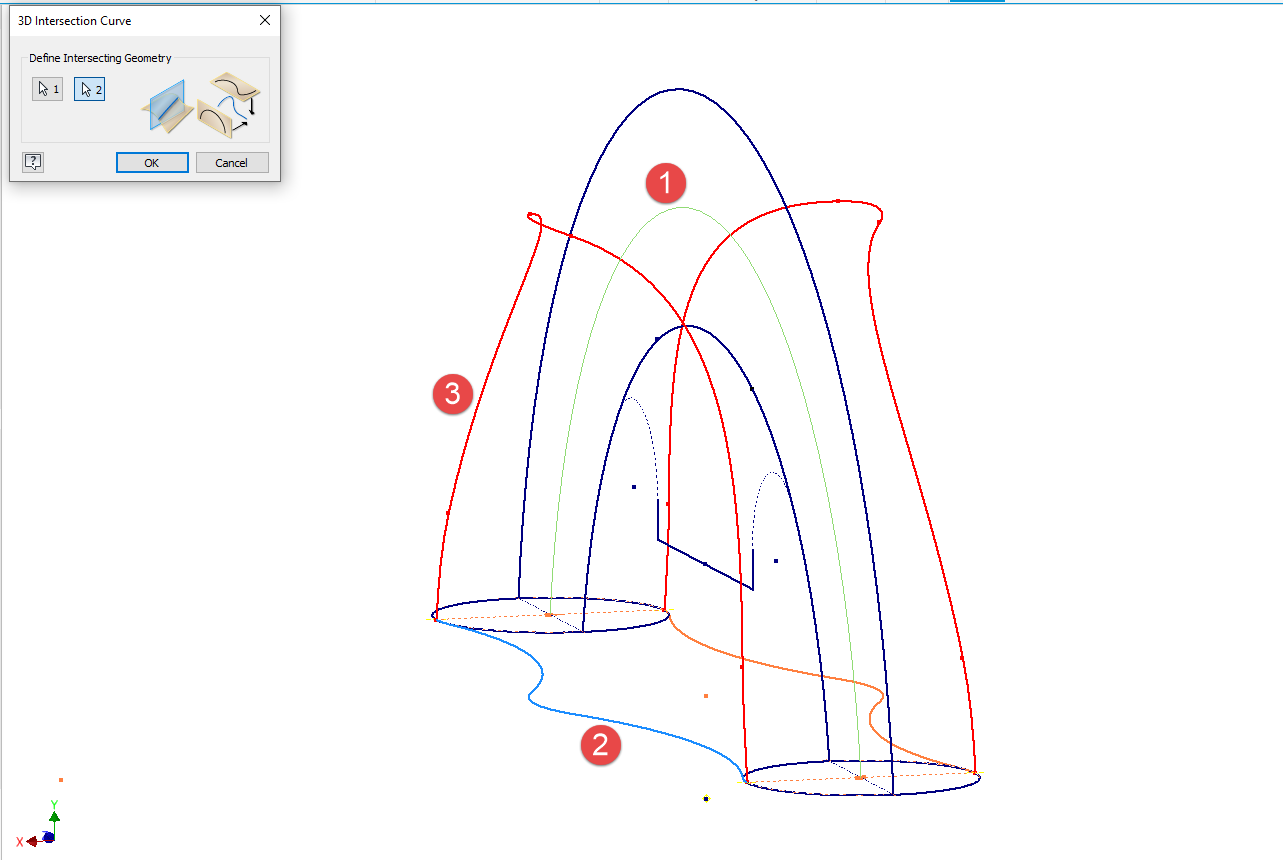
In each case, you’ll notice that these profiles are not closed. The base lines shown in the front view are defined as construction lines, and the end curves in the plan view are also intentional. This design choice allows the main profile lines to be used later for creating a Loft and for selecting a 3D Sketch Intersection. The center line of the arc in the front view will serve as the second selection for this 3D sketch. Additionally, note that the curves in the plan view are elliptical.

The purpose of the 3D Intersection sketch is to define guidelines for the eventual loft. Using the 3D sketch feature, we first select the center line from the front view and one curved edge from the plan view sketch. The resulting intersection will serve as the 3D path for the loft. This process needs to be repeated for both sides of the handle. The ellipses that will form the ends of the loft are created in a separate sketch from the previously mentioned plan view. This keeps them as distinct entities.

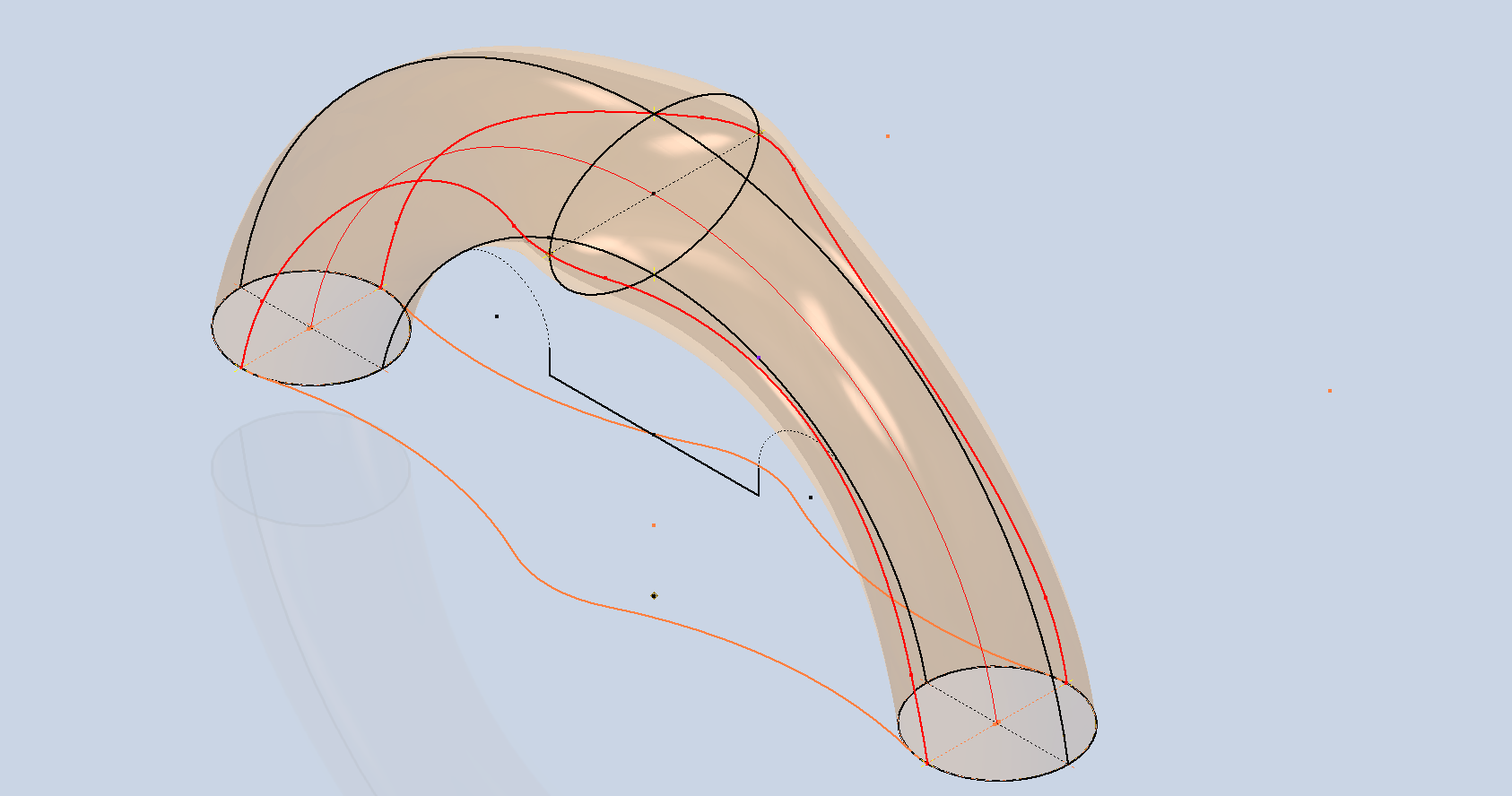
Hold on a moment; where did the ellipse in the middle of the arch come from? If we simply loft the two end profiles of the arch, as shown earlier, we can create an acceptable model, but it won’t be ideal. In the second image, where both surfaces are overlaid, you can see that this approach tends to create a diamond-like cross-section in the center. While this is not entirely incorrect, incorporating the ellipse in the center of the arch results in a much better finished surface, ensuring good continuity, as demonstrated.

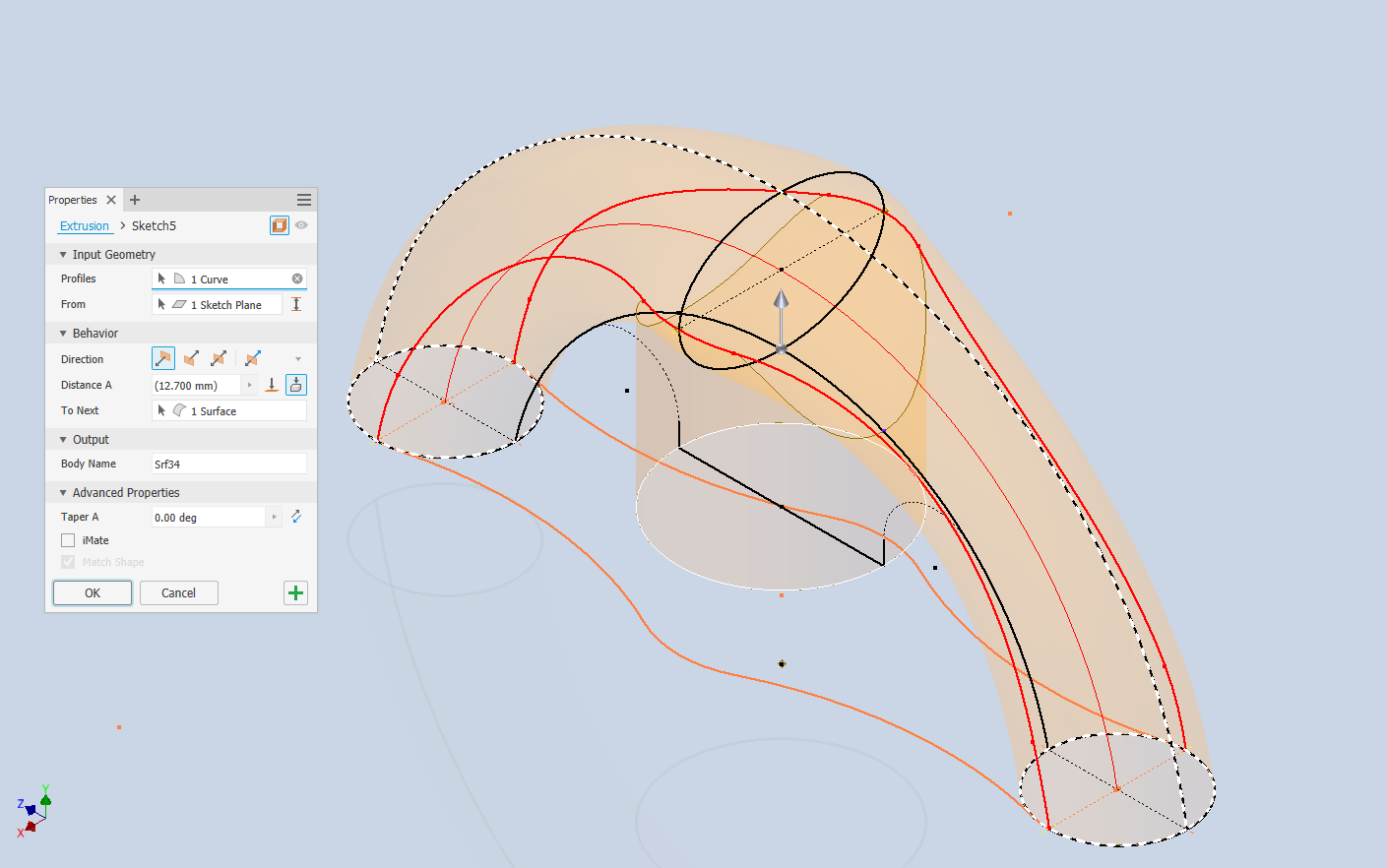
Once we have the arch lofted surface, we extrude the centre section circle to match the surface contours.

We then use this extrusion to trim the underside of the arch surface, apply patch surfaces to fill in the ends of the arch and this centre section. Then stitch everything together and we have the main solid model.

Apply a fillet as shown to the underside; note the fillet in this case is better selected as a tangent fillet and not a G2 curvature. It is often tempting to overuse the G2 fillet option as the perceived notion is that it creates a smoother finish, which by the way is correct, though in a case like this it tends to sharpen the fillet corners which is not good. Something to watch out for when applying fillets.

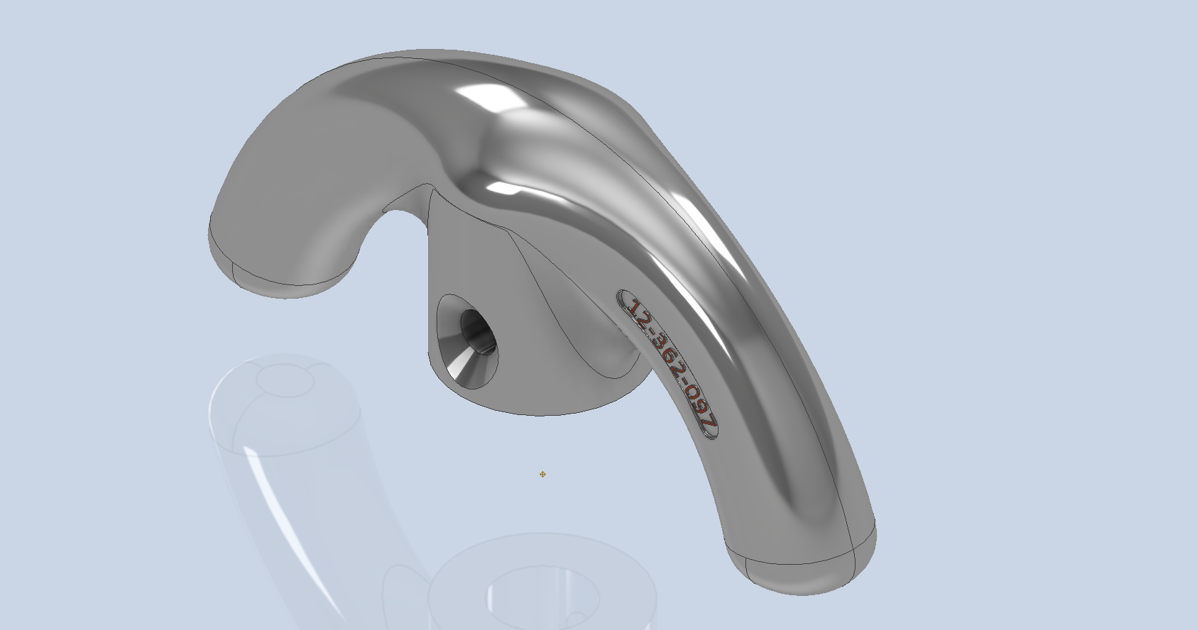
To finish up we add the holes as specified, fillet the ends of the arch (a good opportunity for a G2 fillet) and add the part identifier. The final part should look something like this:

In summary, when developing surface models, it’s beneficial to explore your options and start by creating sketches that support your plan of action. Consider using 3D intersections to define loft paths, and incorporate additional geometry as needed to maintain the circularity and continuity of the final surface.

This part is ready for manufacturing, which will probably be 3D printed for this static display restoration.

Typical Design Workflow:

Usually I would initially receive an inquiry via email from companies like Planes of Fame for a 3D CAD model of a specific part or assembly. Typically, the request includes a brief description of what is needed and not necessarily the actual part number. In this instance, it was for “the handle for operating the window glass.” I then searched through my archives to locate this item, reviewed the part’s blueprint, and checked which parts or assemblies it connects to ensure I have all the relevant information.

I will make every effort to start working on the CAD model as soon as possible, regardless of the time of day, to minimize any delays. For example, I received an inquiry about a part at 9:17 PM last night for the “P-39 Throttle Control Mount.” Following the established procedure, I was able to begin working on it relatively quickly on a Friday evening. The finished part (#12-631-027) was completed and submitted on Saturday at 11:17 AM. The final design included both the original 3D CAD model and a fully dimensioned 2D drawing, which is essential for verifying that all dimensions conform to the original blueprint.

This part will likely be 3D printed for the restoration of the static display, so the 2D drawing serves both as a dimensional check and a reference for manufacturing. If the inquiry had required a metal casting manufacturing process, the drawing would include more detailed information about part machining and the tolerances necessary for a full-metal manufactured item.

If you’re looking to bring your ideas to life with accurate 3D and 2D CAD models for replica parts, I would love to help! Don’t hesitate to get in touch hughtechnotes@gmail.com