Grumman F4F Wildcat: Aileron:

Grumman F4F Wildcat: Aileron:

Having made good progress on the ordinate set for the Grumman F4F/FM2 I decided to put the spreadsheets to one side and do some modeling to verify the dataset. Normally this would not be required to such an extent but I needed to do this to check the relationship between the components and aircraft datums.

I was spoiled with the P-39 project where virtually every component has reference dimensions to the ship center line or thrust lines so positioning was a breeze. However, the F4F drawings sadly lack this reference information on many of the key drawings so developing the 3d cad model is the only sure way to ascertain this data.

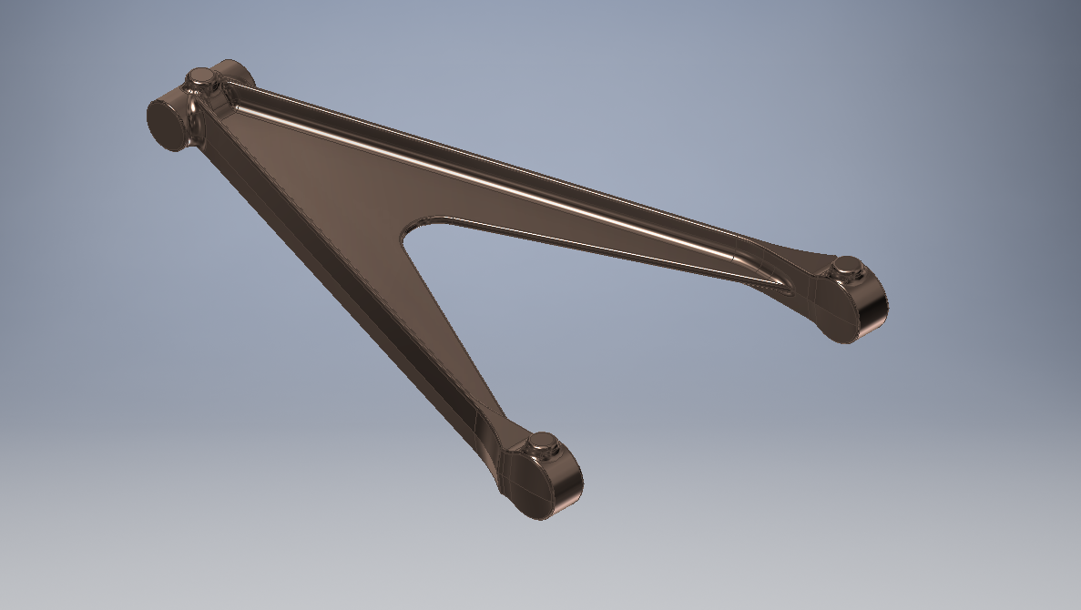
F4F Aileron Render

The above model is the left-hand Aileron modeled in Inventor and rendered in Keyshot. Keyshot is a very good renderer, even for a novice like myself; in which you can generate acceptable renderings very quickly. The real-time rendering is very good and will continue without glitches even on a modestly specced system (unlike some of the alternative products). The user interface is logically set out with a good library of materials and textures. I would highly recommend this product.

Getting back on subject; the Aileron ordinates took a long time to complete for various reasons; requiring constant checking and verifying. Once this was done, the modeling was reasonably straightforward except for the small trimming tab. The drawing dimensions are slightly out, so I extracted the neighboring rib profiles to create the template for a finished model.

I also decided to create a few scrap drawing views as a matter of record that will be useful when I eventually move onto modeling the wings themselves.

F4F Aileron 4

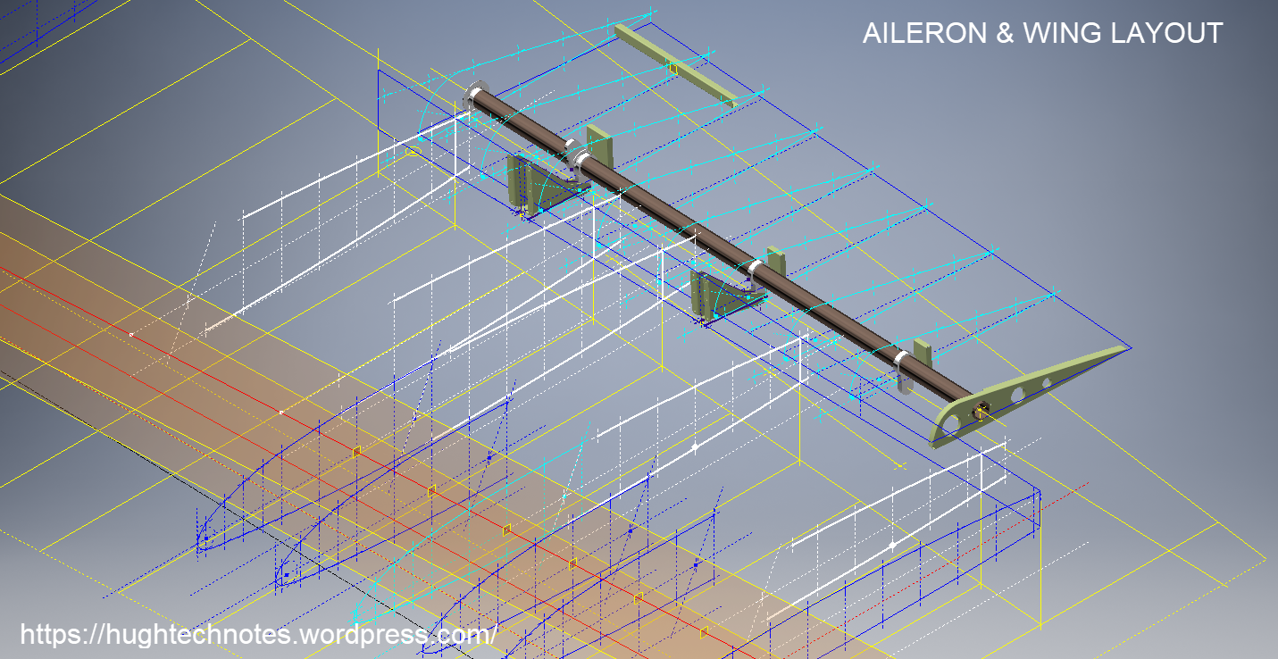
For reference; the following image shows the Ailerons attached to the wing assembly. Hinge positions checked and verified with hinge brackets (orange) fitted achieving a planar variation of less than 0.04mm.

2018-10-07_22-29-40

There are still a few items required to complete this model but this is not a priority for me right now. My next objective is to develop the ordinates and perhaps some modeling for the vertical and horizontal stabilizers.

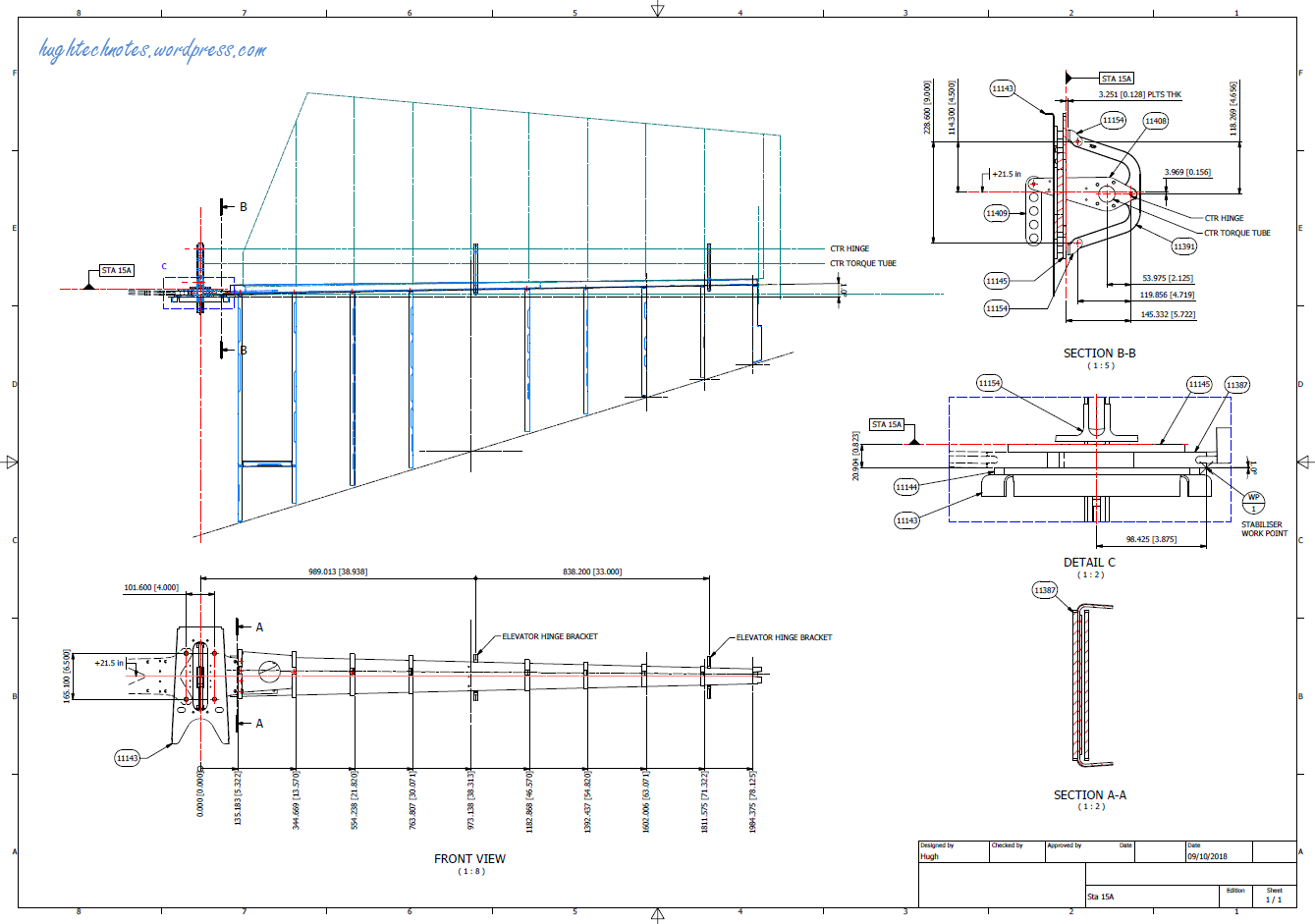
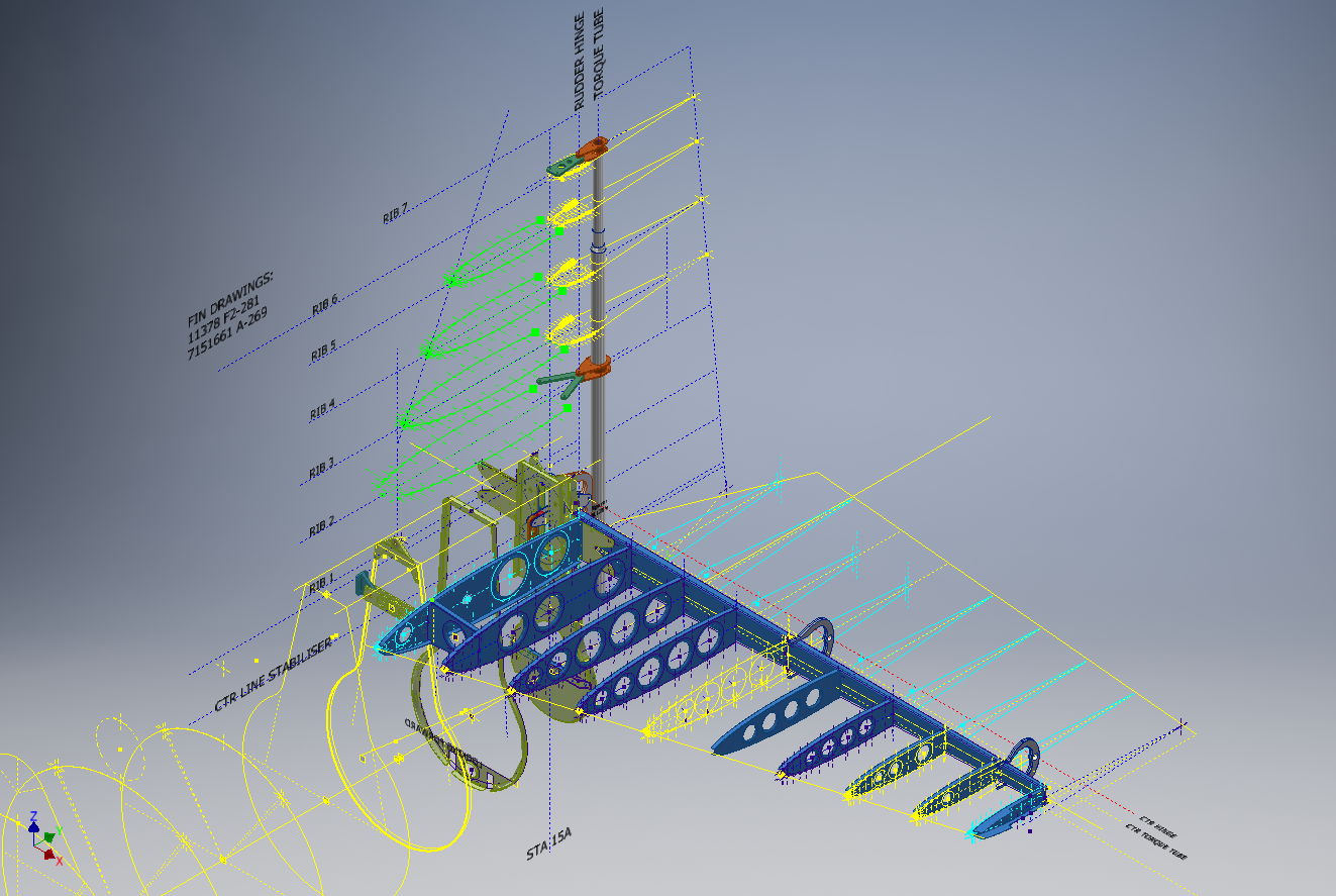
Horizontal Stabiliser & Elevator:

Grumman F4F-FM2 Horiz Stabiliser

F4F Stabiliser

f4f rear fuselage

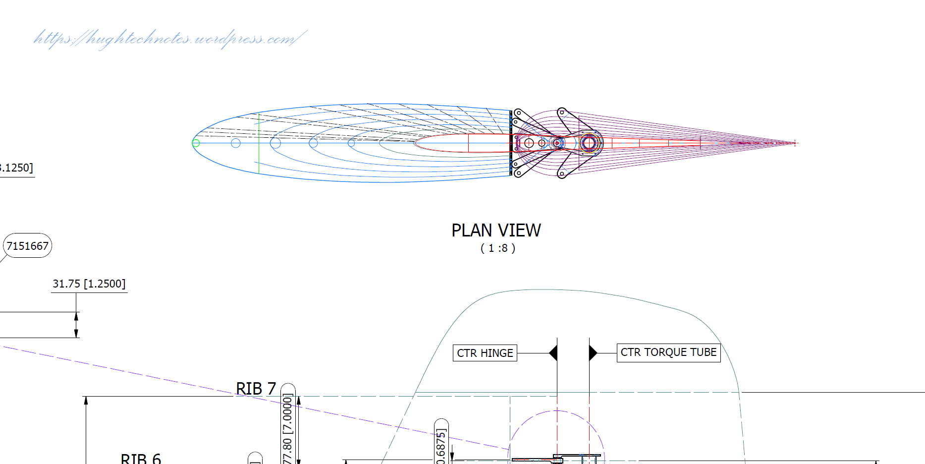
Tail Fin & Rudder:

F4F FIN RUDDER

F4F FIN RUDDER 01

Fuselage Frame 3:

F4F Wildcat Frame 3a

If you are interested in obtaining my research data for this aircraft then please send me an email. At the moment this is an unfinished project but the available drawings (12) are fully dimensioned which will help you with establishing correct datums and station frame associations along with a few spreadsheets. HughTechnotes@gmail.com


Technote: Scaling Ordinates

Technote: Scaling Ordinates:

The primary objective of my work is to record an accurate database of ordinate dimensional data for various aircraft fuselage frames, cowls, wings, cockpit, and stabilizers. This database is derived from manufacturers original documents and drawings.

Often the original source documents are poor quality, occasionally almost illegible, but if we have 95% of the ordinates for a frame then it is relatively straightforward using today’s technologies to determining the missing 5%. Where possible I will cross-reference with part drawings or alternative information to verify.

Cowl nose ring3

However, most archive records are incomplete, as was my frustration with the F6F Hellcat. Having completed the wings, fuselage, and cowl I was stumped by the apparent lack of ordinate data for the tail and horizontal stabilizers (even from part drawings).

There are 2 approaches to determining the missing information. The first is to model the information you do know; from part files, supporting documentation and 3rd part resources. This may provide enough information to determine the missing geometry in order to extrapolate a dimensional data set.

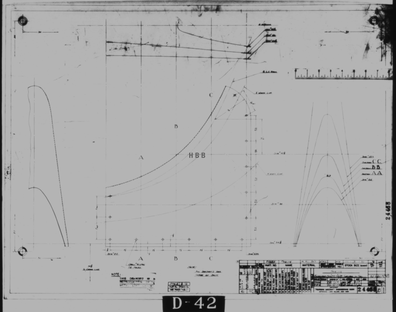
The second; and I would never do this myself; is to trace or convert the outlines of the components from the scanned drawings. There are several products available that will convert raster images to vector files but first, we must achieve a properly scaled image to work with. Most raster image from these archives are scans from 35mm microfilm and due to the nature of the process, the resulting image will not be equally scalable in both X and Y directions.

2018-09-14_14-40-13

Assuming you wish to work with CAD and use this image as a background I would recommend the following process to achieve the best result. This particular drawing is created from actual loft templates and includes the locating pins set to a specified distance in each of the corners plus a drawing scale rule.

Some drawings may only have scale rules, either way, the process is the same.

If we insert this image directly into a drawing in Autocad or similar the only option is a user-defined global scale parameter which will scale the image equally in both X and Y directions, which is not what we want. Even once the image is inserted the option is the same.

The best way to circumvent this is to insert the image into a drawing, without any scale parameters applied. Then save this drawing including the image as a DWG file.

Xref this drawing into another drawing and you will be presented with the following dialogue box ( I am using Draftsight but Autocad will be similar).

2018-09-14_15-30-28

As you can see you now have the option to apply different scales to the X and Y directions. This works very well and will provide a very good reference for your work. I should clarify that some CAD products have the option to insert an image as an Xref but the scaling options are not the same as for a DWG file, instead reverts to a global scale option only.

As a workaround for missing information, this is a very accurate way of achieving a good result and will satisfy the majority of applications.

As my projects are records of known dimensional information this process would not be applicable.

Grumman F6F Hellcat: Ordinates:

Grumman F6F Hellcat: Ordinates:

I have come across some interesting information that has provided some clarification of the cowl ordinates. This has enabled me to further the progress of the F6F Hellcat project.

I have also verified the fuselage ordinates which I have subsequently updated. This project is now looking rather good with wings, front nose ring, air scoop, cowl and of course the fuselage ordinates now complete.

F6F-3

As you can see some preliminary work has also been done on the tailfin which will be closely followed by the horizontal stabilizers and eventually the canopy.

It is unlikely that there is sufficient information to fully complete the Tailfin and Horizontal stabilisers ordinate datasets due to the lack of dimensional data for the tail components. At this stage, the best I can do is locate the 2d plans for this area and hopefully return to this project at a later date when more information becomes available. It has been a challenge getting this far with the project.

Hellcat Ordinates/CAD datasets.

Now available online; a comprehensive package comprising detailed spreadsheets (mm and inch) with supporting Grumman ordinate blueprints, Autocad DWG and original Inventor assembly and part files. The entire package covers 90% of the aircraft geometry. See previous posts for detailed discussions on the development.

For all enquiries please email me for details at hughtechnotes@gmail.com.

Grumman F4F Wildcat: Wing Ribs:

Grumman F4F Wildcat: Wing Ribs:

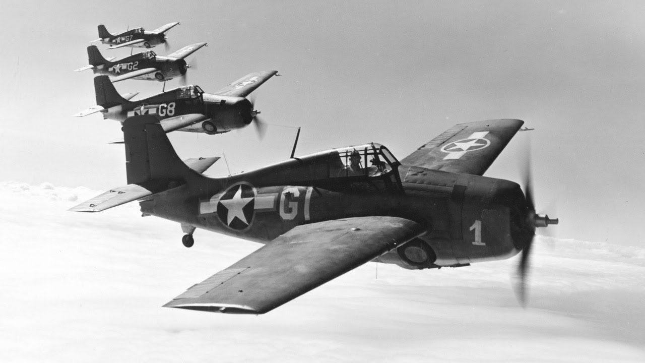
Recently I received an email asking if I had done any work with the Grumman F4F Wildcat. As I do have an archive for this aircraft it was indeed on my to-do list. This inquiry prompted me to have a closer look at the archive to see what information was available to derive a working ordinate dataset.

F4F Wildcat

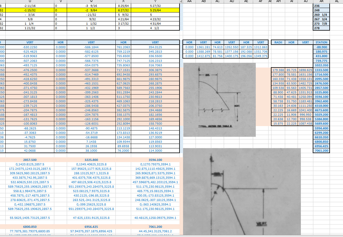
Similar to the P-39 the archive does not contain tabulated data but the part drawings do have the ordinate dimensions. Working to derive an ordinate dataset from part drawings as you can imagine is quite intensive work as you first have to collate the drawings and then develop the profiles in CAD and then extract the point data to a spreadsheet. A complete reversal of the normal process.

The work I was doing for the F6F Hellcat previously was not a priority task so I decided to do some development on the F4F Wildcat, starting with the wings. This threw up a few surprises as the wing rib dimensions were not relative to the wing chord as you would normally expect, instead, they were from a Base datum line. I had not seen this before and it transpires that the reason for this is because the wing ribs are actually not perpendicular to the wing chord. They are in fact perpendicular to wing datum line.

F4F Wing Ribs

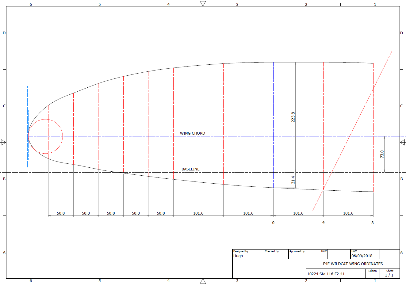
This next image shows a simplified sketch of how the dimensions are shown on the Grumman drawings. Note also that the vertical divisions are dimensions fore and aft of the “0” line (which I take to be the vertical datum) and not percentage breakdown of the cord length as expected.

F4F Wing Ribs2

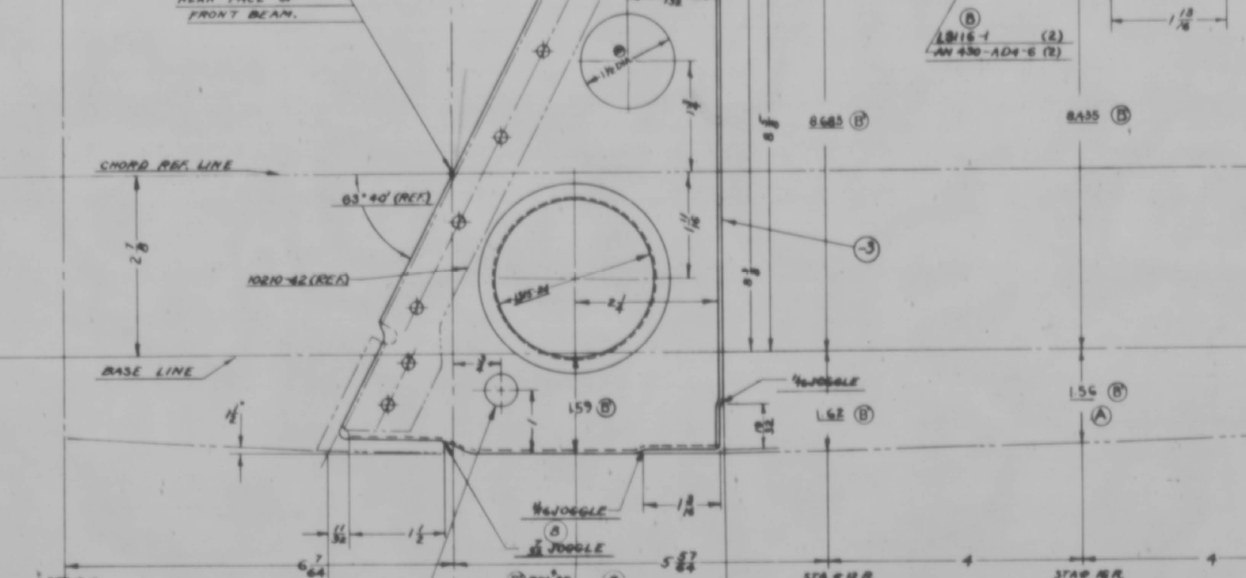
This raises all sorts of questions as to why Grumman designed the wing structure in this manner. I cannot think of any performance or manufacturing benefit in doing so. You can also see in this scrap view from an actual Grumman drawing how the dimensions are to the baseline and not the chord line.

F4F Wing Ribs3

I posted a similar question on the WW2 Aircraft forum, so hopefully, someone will enlighten me on this unusual design feature.

Update: Solved!

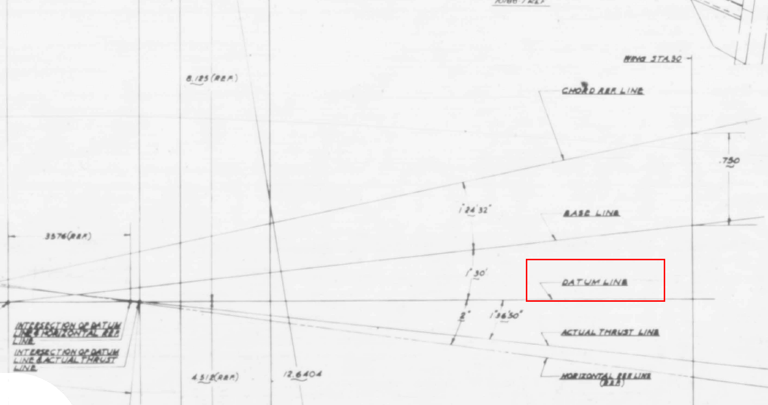
The wing ribs are perpendicular to the Wing Datum line, which is 1.6 degrees from the Thrust Line (essentially the design horizontal axis) that aligns with the fuselage Thrust Line. It transpires that the various wing components are dimensioned relative to any one of 5 different datums depending on their function.

2018-09-16_01-23-03

Update Sept 2018: Work in Progress:

F4F Aileron 2

2018-10-06_19-18-41

Grumman F6F Hellcat: Cowl Ordinates

Grumman F6F Hellcat: Cowl Ordinates:

I may have been a tad over-optimistic in my previous article on the F6F ordinates when I mentioned there was a good chance the Grumman ordinate data would be complete. The one exception is the cowl, although there is an ordinate drawing for the cowl the table itself is just a black blob, completely illegible. However, I checked the part drawings that make up the cowl which is quite well detailed so I made a start on the nose spinner ring.

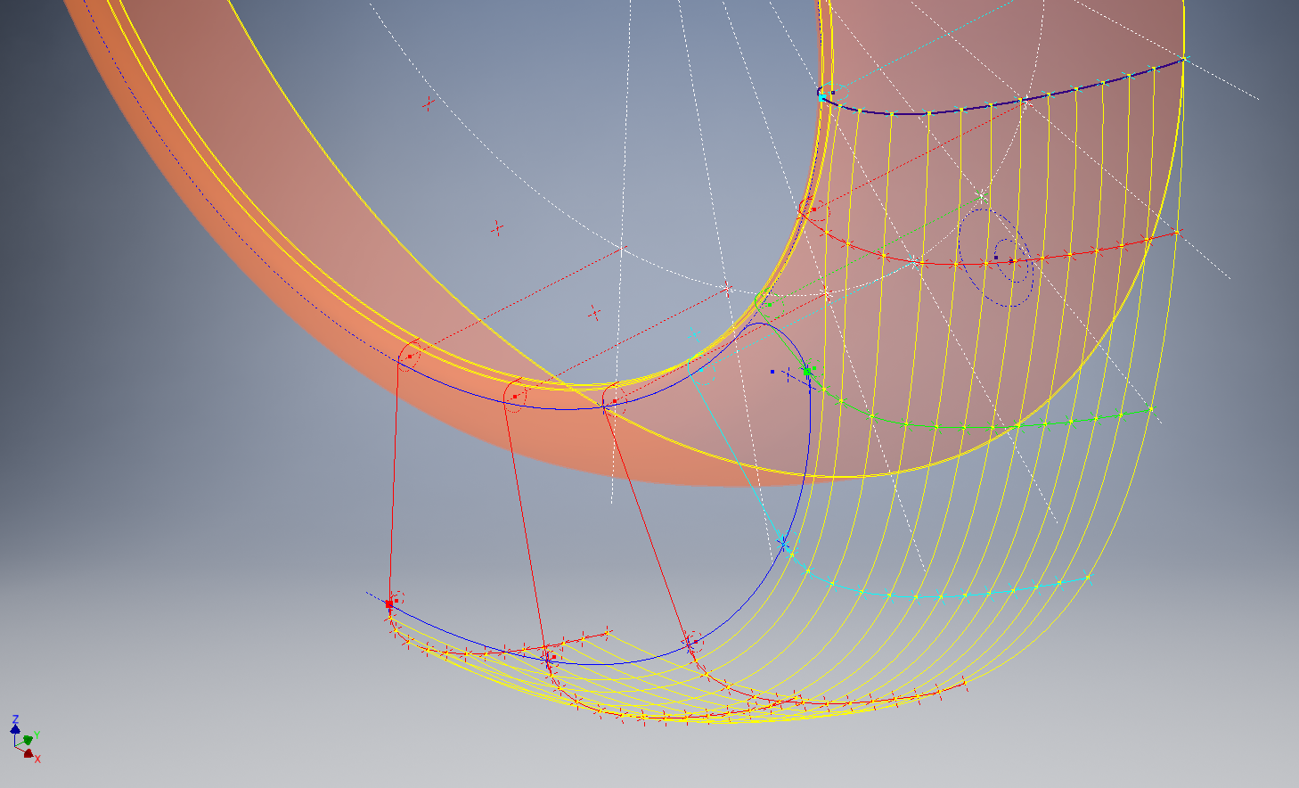
The spinner ring main model is fine and here it is derived into the air scoop construction model. The construction requires numerous contour lines as each ordinate needs to be manually checked due to the poor quality of the original Grumman drawing scan.

Cowl nose ring3

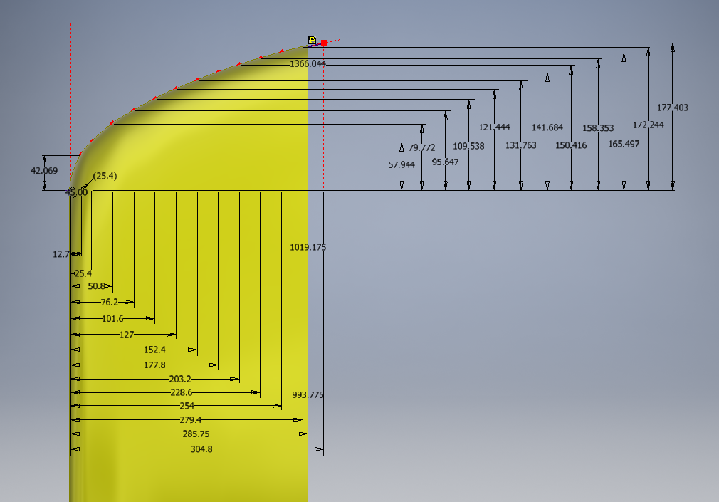
This ordinate drawing is not deliberately blurred by me, this is how it actually looks like. The main dimension is almost legible just the fractions that are problematic. The process will require evaluating each contour line and curvature check, both horizontal and vertical as shown in the above image.

I am hopeful of achieving a good result with this model which will probably take a few days to complete.

Update 27th August:

F6F Cowl Nose Ring2

I have now determined the correct ordinates for each of the seven profiles. Notice the lower profiles have been artificially extended to the center ring, which will give me better results when lofting. After lofting a surface the plan then is to remove the mouth of the air scoop (blue) and apply the finishing flange to the inner edge.

F6F Cowl Nose Ring80

The ordinates are recorded in a spreadsheet with the x,y,z coordinates extrapolated as I previously did for the wings and fuselage.

Update: 12 Sept 2018:

Cowl Ring Cowl Nose setout dimensions verified.

F6F Ring Cowl Nose

Ordinate Dataset Completed: Wings, Fuselage and Front Air Scoop.

The F6F archive of scanned Grumman documents comprises over 7000 drawings in PDF.

Grumman F6F Hellcat: Wing Ordinates

Grumman F6F Hellcat: Wing Ordinates

I wrote an earlier article on my work with the F6F fuselage ordinates which I have recently updated. Whilst revisiting the archive I also came across the Grumman wing ordinate drawings and decided to develop those as well. I was reluctant to do this as the original drawings were not that great.

Thankfully it was not as bad as I first suspected, though it has taken me over 7 hours to painstakingly enter each ordinate manually to tabulate the ordinates in Excel.

F6F Wings

I still have to interpolate the data to generate the appropriate X, Y, Z coordinates; set out from the 35% chord; which I will endeavor to do over the next few days.

F6F wings 2

To verify the ordinate dimensions the following equations are applied. The chord length is for any wing chord whilst the LER is only applicable from station 75 to station 252.

f6f calcs2

To be honest the F6F Hellcat was not even on my to-do-list but a conversation with a colleague about the F6F performance characteristics prompted me to have a closer look at the archive. Surprisingly it is very possible that this archive may have sufficient information to generate an entire aircraft ordinate set, which is quite rare.

f6f

I will update this post when the wing model is complete, so come back soon.

Update August 23:


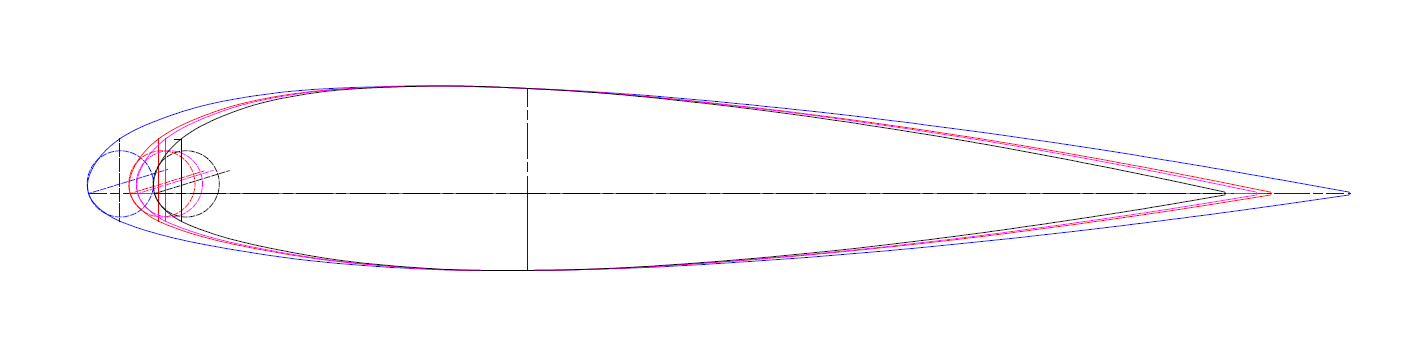
I have checked the Centre section profile for accuracy and noticed one point out of alignment by 2mm towards the leading edge. Removing this point allowed the natural curvature of the spline to define an acceptable profile as shown. The curvature check shows that this curve now matches the Leading Edge Radius.

The trailing edge extends beyond the 100% Chord by 5/8th inch on the centre section (Station 0) which tapers to zero at Station 252. Drawing a straight line segment from the Trailing Edge Radius results in perfect alignment with the spline.

Centre Section Stations:

f6f ctr section

Outer Panel Stations:

F6F outer wing

It is not unusual to have a few rogue points from the tabulated ordinate data which is why it is important for a detailed analysis like this.

And here, at last, the complete wing assembly:

f6f wing assembly

Restoration Project: Corsair F4U-1

Restoration Project: Corsair F4U-1

This is great news; a good friend of mine has just acquired the wreckage remains of a Corsair F4u-1.

IMAG1368

The long-term plan is to restore this Corsair to its original specification as a standing exhibit. It would be wonderful to restore to flying condition but the projected cost as it stands is quite overwhelming and to achieve flight status would probably double that.


IMG_4038.JPG

P1060200.JPG

We will be setting up a dedicated blog and website to record progress on this restoration. Part one of the project is to develop a master lines plan which will be used to design the jigs required to rebuild the fuselage and wings.

Any contributions to the project, regardless of how small will be greatly appreciated.

Technote: Inventor Sketch Datum

Technote: Inventor Sketch Datum Point.

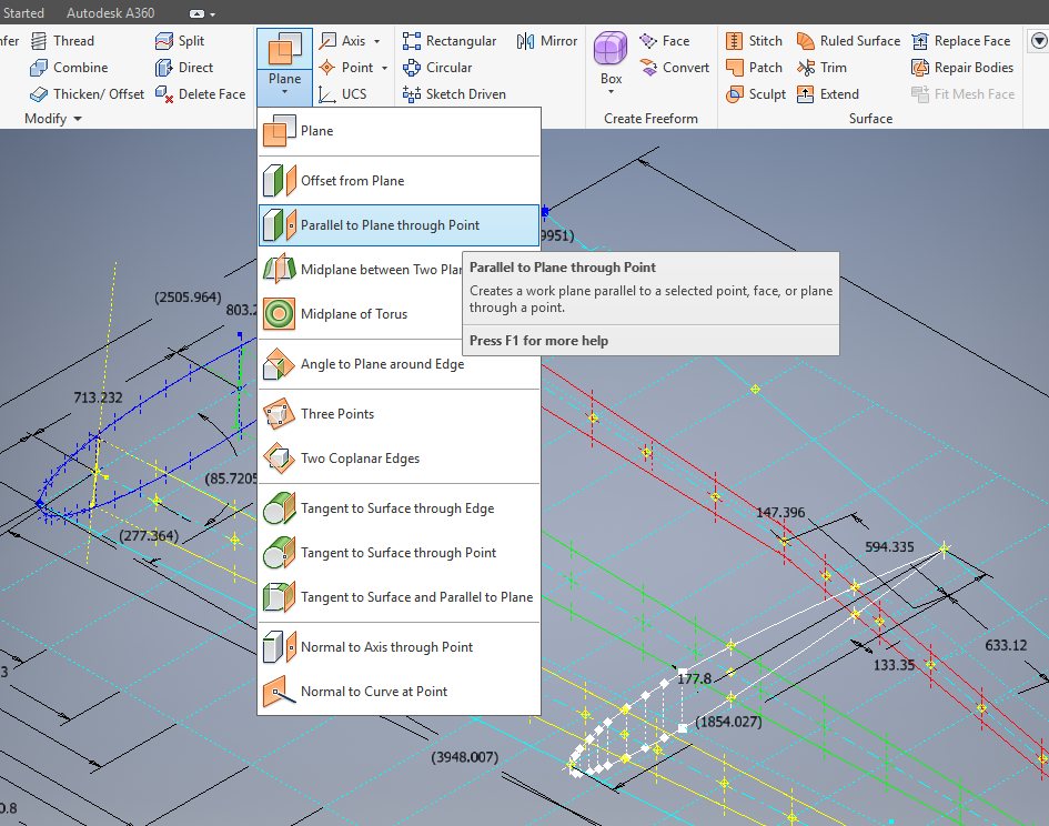
This is one of those instances where you do something on a regular basis and don’t really appreciate the significance of the process. What I am referring to is when you create a sketch Plane using the option “Parallel to Plane Through Point”.

2017-07-27_00-33-25

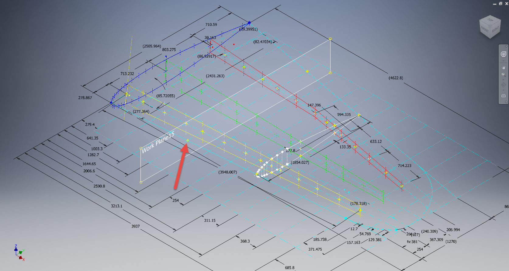
It transpires that this selected point becomes the datum for the particular sketch created on this plane. For this example, for a P-39 wing rib, we have selected a point for the Plane location along the wing leading edge as shown.

P39 wing1

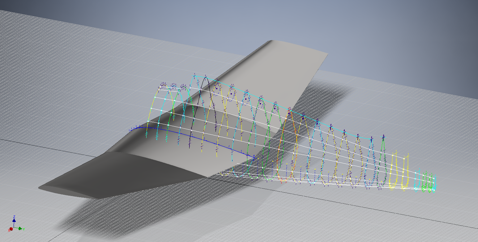
The Bell P-39 and similarly for the P-51 Mustang the wing ordinates are set out from the leading edge of the wing so it makes sense that the rib sketch is setup with a suitable datum point. You can tell the location of the temporary datum in the sketch applied to this plane by the position of the main axis.

This is the really interesting part, when you now import a set of points from the Ordinate spreadsheets it will recognize this sketch datum and import the points relative to this point irrespective of the model origin.

2017-07-27_00-35-12

2017-07-27_00-39-42

This is very useful particularly for these aircraft projects as we tend to use a lot of ordinate data for the outline geometry.

Another Quick Tip:

To automatically apply a tangent constraint to a sketch line just select and drag the line from an existing line and the tangent constraint will be applied.

2017-07-27_01-14-56

Technote: P-39 Inventor Facedraft

Technote: Bell P-39, Inventor FaceDraft

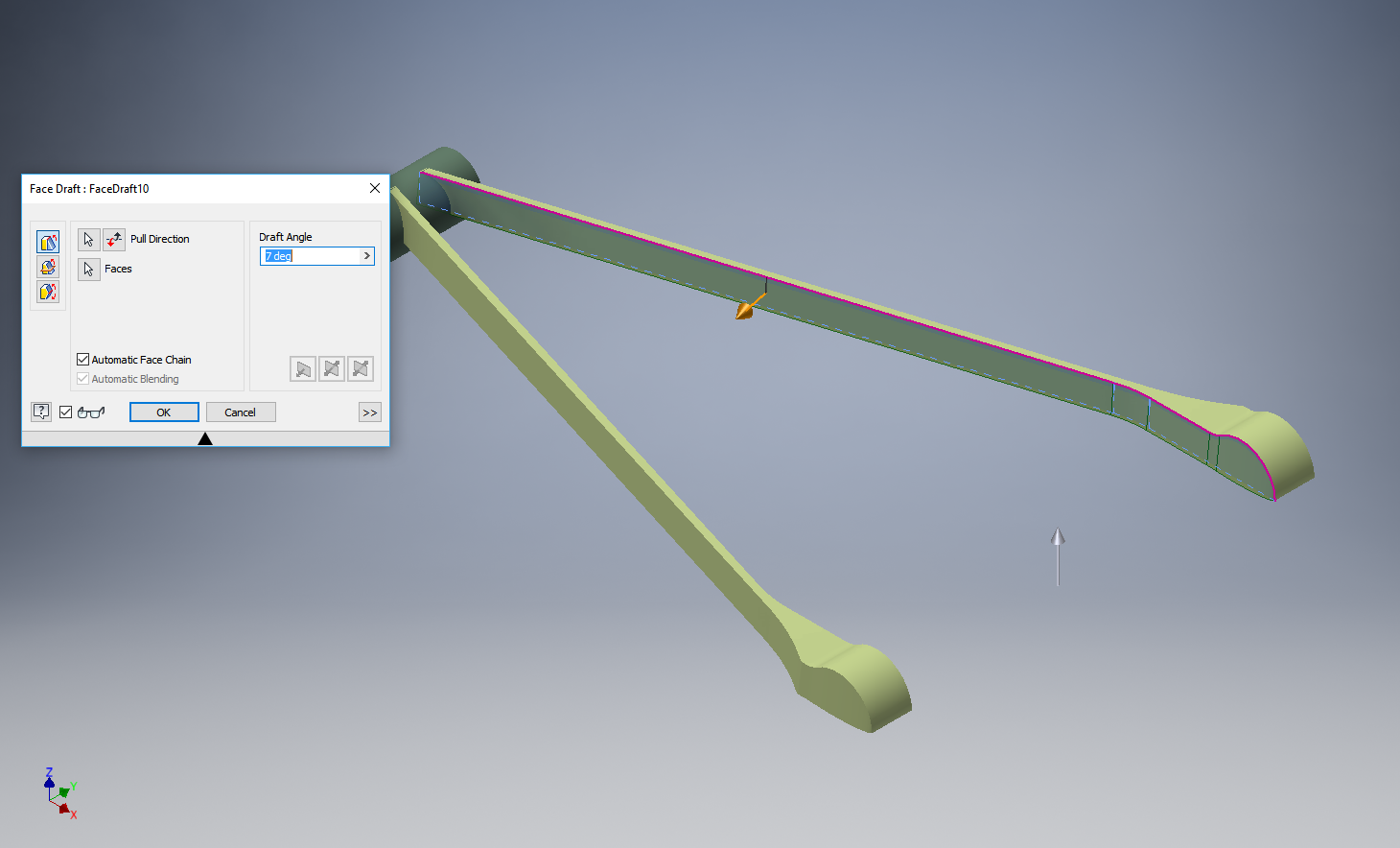
Draft angles is actually a common requirement when working with aircraft components, particularly forgings, and it is surprising that I haven’t written an article on this before now.

Facedraft in Inventor is a feature that allows adjusting the face or faces of an object to a specified angle. A more detailed overview is described in this Autodesk article Face Draft feature

Occasionally the implementation is not quite so straightforward as noted therein and some outside the box thinking is necessary. Thus was the case when I was building the forging component for the P-39 Landing Gear Nosewheel Scissor.

To build this component I created 2 separate solid bodies, one for the cylinder item and one for the fork. The fork is split about the X,Y plane with only the outline of the top half being modeled to facilitate the initial face draft.

2017-07-23_00-00-14

For the first option, I selected the X,Y plane and then for the Faces I selected the automatic face chain option and placed the cursor close to the top edge as shown. If you required the face angle to originate from the bottom edge then you would select the faces close to this edge.

I then trimmed out the inside profile of the fork and applied a face draft as above.

2017-07-23_00-08-00

Now it was only a matter of mirroring the fork solid to complete this portion. Notice the solids are still separate items which will be combined as one after inclusion of the central web component.

2017-07-23_00-12-51

There is an option for the Facedraft feature to Draft using a parting line, either a 2d or 3d sketch. The draft is normally applied above and below this parting line. In most circumstances, the Parting Line option works well but occasionally the model may be too complex to achieve the desired result thus the solution described here provides an alternative approach.

Forgings or castings commonly have a draft angle on all faces which is normally 7 degrees and occasionally 5 degrees. The Face Draft feature is ideal for applying the drafts with an extensive range of options. The model of the forging would then be derived into a separate part file and then machined according to the finishing requirements similar to the process described here Derived Parts.

2017-07-23_11-47-28

2017-07-23_11-46-40

For more information on the Bell P-39 Airacobra project: Bell P-39: Project

Technote: Inventor Export Sketches

Technote: Export Sketches

The Inventor product has an option to export part Sketches to either an Autocad DWG or DXF format directly from the model environment. This is very useful if you are needing to share development information with someone else who is working with a different CAD product.

It is simply a case of highlighting the sketch as shown in the example below and selecting the “Export Sketch as…” option.

Inventor export sketch

A dialogue box pops up asking for the file format DWG or DXF and location for saving. I would recommend the DWG for the format as this replicates the Splines more accurately.


In this example the left image is for the Mustang P-51 rear fuselage, showing the outer profile for the P-51 B/C and the inner profile is for the P-51D. The image on the right is the fuselage tail-end.

I plan on extracting all the fuselage curves that include P-51D data to DWG format as a reference until such time as I can add the point data to the already comprehensive set of ordinates available here.

Mustang P-51 B/C Ordinates