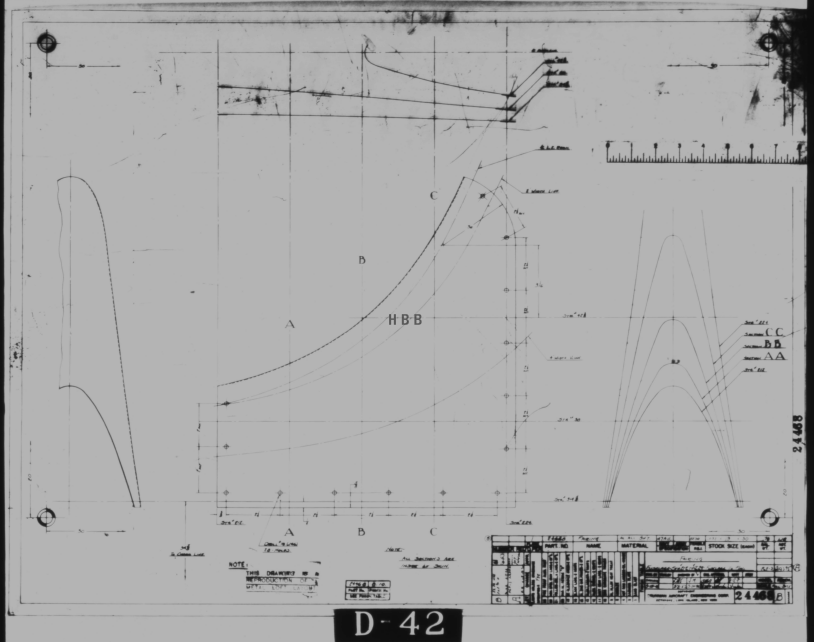
A quick technote on entering a conic formula in MS Excel spreadsheets. Getting the correct syntax is critical to achieving correct results.
I am updating the ordinate datasheets for the P-51 B/C and D models to incorporate new information using the various conic formula according to the curve type. Typically with these equations, there are a number of constants to be established to input to the final quadratic formula.
The original formula for one of the constants “P” is given as shown (1). If we enter the formula as prescribed in a hand calculator it will evaluate correctly but will not work correctly in Excel in this format. So we need to tell Excel to essentially divide everything in the top line by everything in the bottom by adding parenthesis as shown (2).
The bottom line shows the actual input in the excel formula bar (3).
We are continually working on updates to the Ordinate and Cad package so watch this space for new articles. There will also be in-depth tutorials on interrogating ordinate information to find max-width, tangents and matched second-degree curves as well as updates on detail drawings.
I have recently been working on updates to the Ordinate and Cad package (as noted in the previous posting) and also developing the Instrumentation panel assemblies for the P-51D Mustang.
What started out as a mere curiosity is actually turning out to be a fairly intensive project requiring a lot of research.
For the P-51D there are at least 4 variations on the main instrumentation panel for the early and late models. The U-shaped Support frame has 4 variations and just as many for the lower instruments panel set at 20 degrees to the main panel. It is important to get the correct combination of components for the various model numbers which is where a lot of my time is spent on the research.
Part of that research is, of course, getting the label text just right which is where I encountered a lot of frustration. The generic text font used on the Mustang and many of the contemporary aircraft at that time was the MS-33558. There is a TTF font available online for download but the design is not very good with problems of self-intersecting edges and spacing definition.
Using this font in CAD systems will result in problems with embossing or extruding.
Typically I had to find out why, so I downloaded a copy of Fontforge to analyze the characters and identify the problems. Most of the characters are fine but there are at least 7 that have intersecting line problems. However, due to the nature of the font construction process, it is very difficult to identify the problem areas and thereby to devise a solution.
I spent a few hours looking into this but font development is a relatively new procedure for me and I did not achieve any satisfactory results. This I think needs an expert touch. I appreciate the work that was done in developing this TTF but please whoever designed it just a bit more attention to detail would have saved me a lot of work.
In the interim, I decided to use the closest font I could find on my system which was a default SolidEdge font that is similar in style. I had SolidEdge as a trial program a while back and thankfully it left the fonts behind when I uninstalled it.
Another small point worth noting is the color of the label text. The images above show the early P-51D version arrangement and you will notice in the bottom left corner of the first image is a selection of text in red. It is “EMERGENCY” with an associated note. The drawing states that this is RED on a black background but many of the photos I have seen of this particular version show the text in white. So the question is did NAA change this at some stage or is it just down to restorers’ preference?
A comprehensive overview of the Ordinate/CAD package for the P-51 Mustang B,C and D aircraft. This package is the result of over 2 years of extensive research and development incorporating everything I know about the ordinate information pertinent to the P-51 Mustang; now available for download.
Fully Dimensioned Layout Drawings (Autocad 2d):
These are my CAD files that you can use for your own projects. These files are being made available for personal use only and not for commercial gain. Detailed layouts, fully dimensioned.
Tip 1: The Engine Mount drawing is a good starting point when setting out your CAD model. This will establish the fuselage datum points, Thrust line, Engine mount locations, and Firewall.
The dimensions for this have been triple checked. Incorporates information extrapolated from 6 different documents.
Tip2: Did you know you can work with inch and mm dimensions in the same model. If you happen to be using an mm template and wish to input inch dimensions then just type in the value followed by the unit type; either “ or in. So for 1 3/8in enter exactly as shown including space and vice versa if working in the inch template and using mm just quote mm units.
Over 228 Autocad 2D Point Profiles Derived from Spreadsheets:
These are my CAD files (DWG) that you can use for your own projects incorporating the point data. These files are being made available for personal use only and not for commercial gain. 2D profiles of all frames for wings and fuselage.
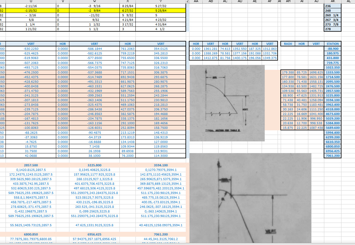
Ordinate Spreadsheets: 1000’s of Ordinate Point Coordinates (mm and inch):
These are my Excel spreadsheet files that you can use for your own projects. These files are being made available for personal use only and not for commercial gain. All ordinate points painstakingly entered by hand in both mm and inches. Data is sorted and extrapolated to derive 3d coordinates for direct input into most CAD systems.
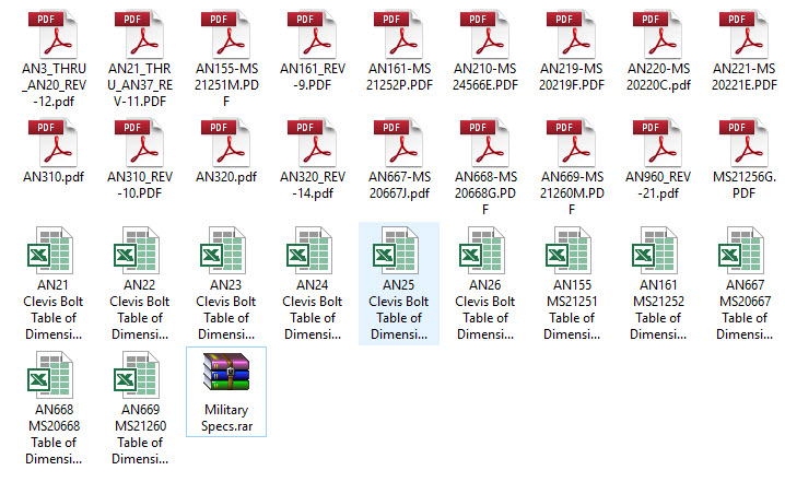
Original Military Specs AN & MS (fair share) with Dimension Spreadsheets:
Standard specifications and dimensions for parts including turnbuckles, bolts, nuts washers etc. 3D CAD models of these parts are available separately as a collection; refer to the CAD library tab. Relevant parameters are recorded in spreadsheets that can link to CAD models.
The full Ordinate/CAD dataset will literally save you 100’s of hours of tedious work and is available online. For further information please send an email to hughtechnotes@gmail.com
This Ordinate/CAD dataset is only available from my blog. All work and research were done by me. All spreadsheets and DWG files are fully editable.
Models on CGTrader:
Alongside the ordinate and dimensional research I also have a large number of professionally prepared 3D CAD models for the P-51 Mustang now available for download on CGTrader.These include the Tailwheel assembly for the P-51 Mustang. All parts, including all internal components, nuts, bolts, washers, and pins modeled to original standards. Tailwheel CAD assemblies on CgTrader:
exit These CAD models include fully itemized layouts for each assembly.se
As usual please get in touch at the following address for all inquires HughTechnotes@gmail.com
I recently received an inquiry from a museum regarding ordinate datasets for the Bf109. As I previously mentioned in this earlier post the archive I have has a lot of data that was done by others…so I figured it was quite comprehensively covered.
Anyway, I decided to have a closer look and see what was actually documented and how well it aligned with known data. It turns out to be a bit of a muddle. Although the data is quite well presented I have uncovered a number of inconsistencies and anomalies which I will need to resolve.
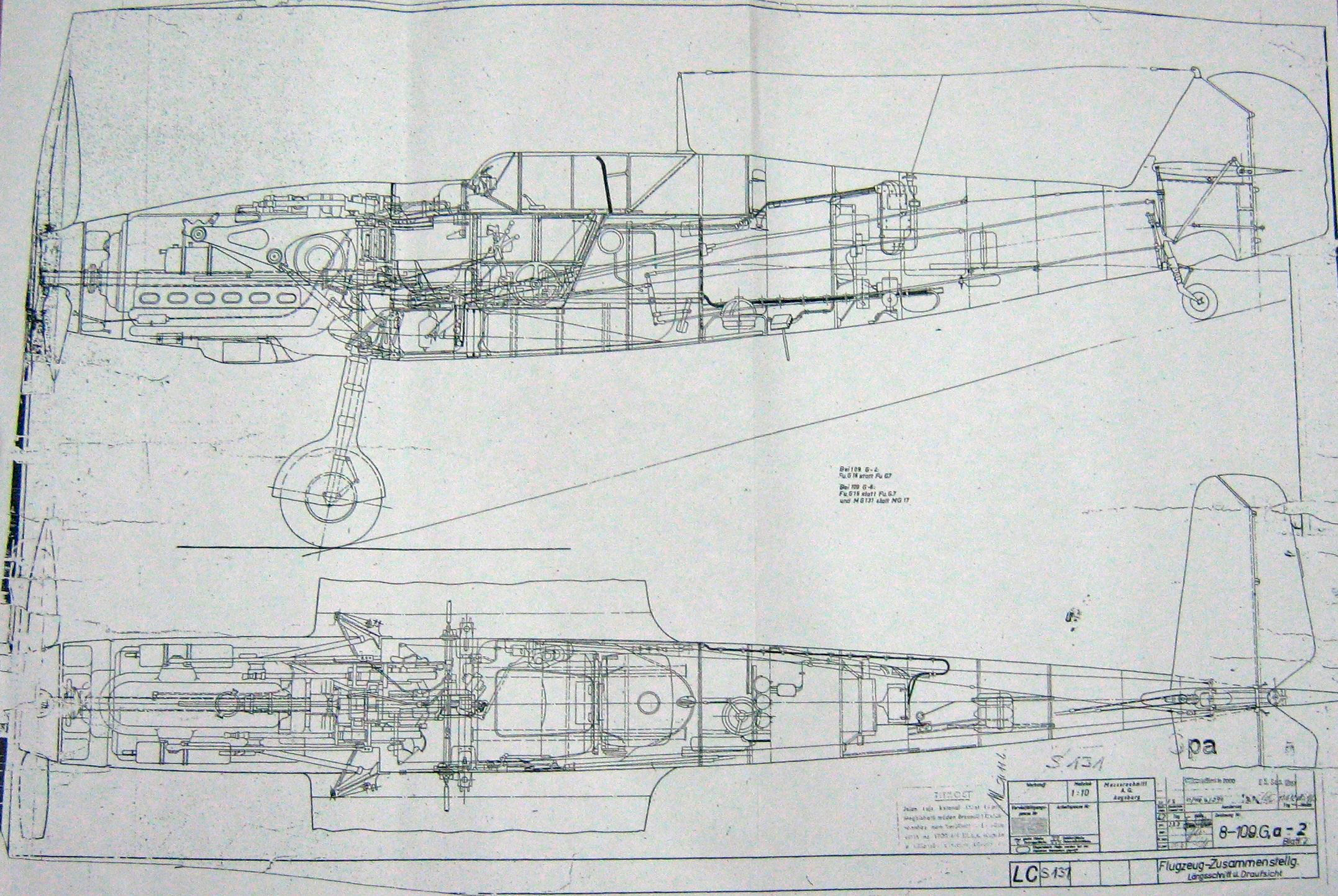
What I thought would be a quick response to an inquiry has initiated a much more intensive study which admittedly I had not planned for. I will go back to basics with this one, using the existing data as a reference and develop a new set of ordinate data for the Bf109 similar to how I approached the Mustang P-51 project.
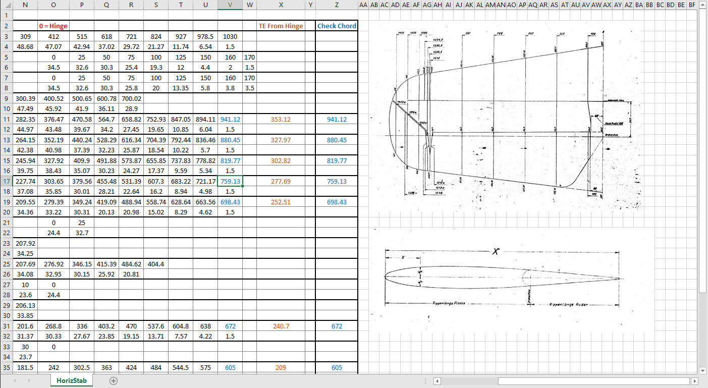
I have already started with the Horizontal Stabiliser and part of the way through the Vertical. The tables will essentially be a reconstruction from the Messerschmitt drawings and then compiled to develop the X, Y, Z ordinates for transfer to CAD.
Photogrammetry has come a long way since I first came across it when working for an Offshore Oil & Gas company in the mid 90’s. This company had a department dedicated to researching Photogrammetry and 3d Scanning for surveying existing Process Plant installations.
Fascinating stuff and it actually worked using predefined targets placed at strategic intervals on the existing plant.
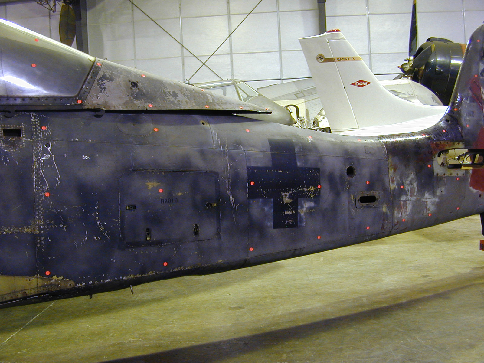
The Aviation restoration companies have for a long time been using 3d scanning and photogrammetry. In fact, if I recall correctly the Smithsonian carried out a survey of the Ta152 which I believe was Photogrammtrey many moons ago. If you look closely at the following image you can see the red dot markers to help ascertain dimensional and positional data from the scans. If anyone out there has access to a copy of the survey results I sure would be interested in seeing them.
So not willing to fall behind on the latest technologies I endeavored to find out what has been happening with Photogrammetry and played about with some of the available software products. The software I looked at was 3DF Zephyr, Meshroom and Reality Capture. I had a lot of fun but as you may have noted in my previous post the laptop I was using was really not up to the task, nevertheless, I persevered with my research and attained a few good models which surprisingly worked very well.
I even went as far as designing a lightweight support mechanism for photographing fossils in the field. Often these are Sites of Special Scientific Interest (SSSI) in the UK, which is a conservation designation denoting a protected area. Essentially legislation for legal nature/geological conservation of land considered of special interest for their flora or fauna, geology or geomorphology.
Unfortunately, for many of these sites, the removal of fossils is frowned upon so the Fossil Pod was designed to facilitate taking photographs of the found objects…an adapted use for Tensegrity design.
It is early days in my research which I intend to continue to explore options for increasing dimensional accuracy using photogrammetry and obviate the limitations for shiny and reflective objects. I appreciate that the industry may be more interested in 3d laser scanning technologies which is essential for accuracy but I feel that photogrammetry has a lot to offer for presentation and grasping details when a 3d scanner is not available.
As for the software, I would recommend both the 3DF Zephyr and the Reality capture. I should note that all 3 software products do exceptional model generation from photographs however the Meshroom; though in early production; is much less forgiving and requires a very good dataset to work from whereas the others are more tolerant.
If you would like some inspiration for what photogrammetry can do check out this Youtube video from the Swedish Exhibition Agency.
I am currently working on the Landing Gear geometry dimensions to check the data for accuracy. During the course of this research, I thought it may be of interest to share some Excel formula for converting angles shown in Deg Min Sec to decimal degrees and vice versa.
The plan angle for the OLEO Strut relative to 25% wing chord is 4° 32′ 35.14″ as shown in the above sketch which translates to 4.543094 degrees.
The accuracy of the angles and dimensions in the NAA documentation is rather good with small deviations occurring of only 0.003mm when developing this in CAD. I should note this deviation is negligible and for all intents and purposes can be ignored. However, I like to get this stuff right so I have set about developing the landing gear dimensions to be as close as possible to be exact.
As I have already developed the cad geometry I measured the same angle above from the CAD system which is now giving me 4.54309673 degrees.
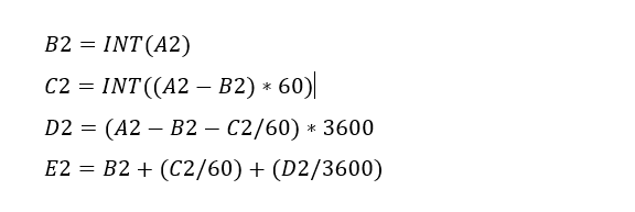
In Excel:
Starting from the left; in column A; I have input the angle from the cad system, then systematically converted to Deg, Min, Sec in separate cells and then converted back to a decimal angle in column E.
The equations for each cell are as shown below:
Just enter the equation in the cells denoted; so for the first equation, this would be in cell B2. The latter equation works fine without parenthesis, which I included just to keep the equation tidy.
The Landing gear geometry will be recorded in a separate spreadsheet and added to the P-51 Ordinate Package. Mustang P-51 Ordinates
Following a recent inquiry, I have revisited the NAA P-51 Mustang project to develop the front fuselage and cockpit. This will be an extremely detailed and accurate model including fixings and rivet holes.
The partial structure above is for the early P-51D version; note the instrument panel and support frame. There are also some minor differences with the other components, most notably the curved beam which has different end brackets for the early and late versions.
The 2 instrument panels depicting the P-51D versions, with the later version on the right. This will be a medium to long term project for which I will post regular updates.
Having made good progress on the ordinate set for the Grumman F4F/FM2 I decided to put the spreadsheets to one side and do some modeling to verify the dataset. Normally this would not be required to such an extent but I needed to do this to check the relationship between the components and aircraft datums.
I was spoiled with the P-39 project where virtually every component has reference dimensions to the ship center line or thrust lines so positioning was a breeze. However, the F4F drawings sadly lack this reference information on many of the key drawings so developing the 3d cad model is the only sure way to ascertain this data.
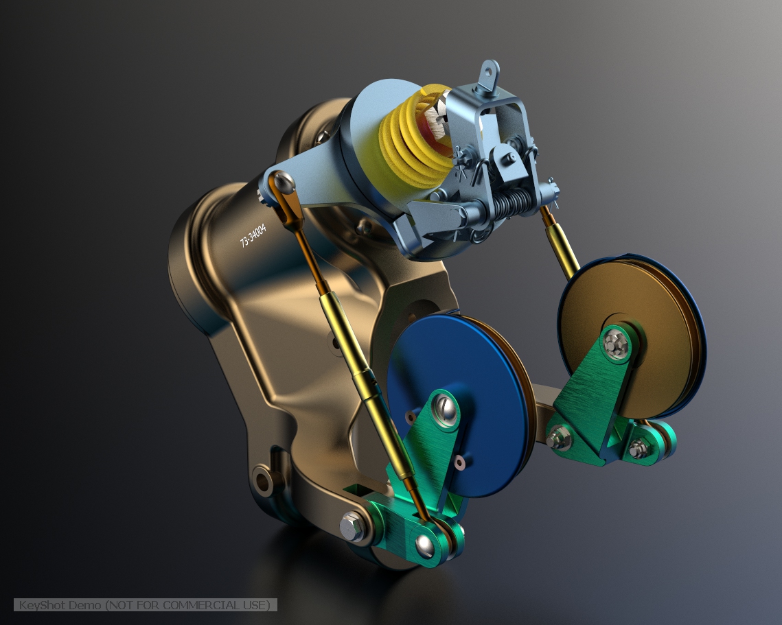
The above model is the left-hand Aileron modeled in Inventor and rendered in Keyshot. Keyshot is a very good renderer, even for a novice like myself; in which you can generate acceptable renderings very quickly. The real-time rendering is very good and will continue without glitches even on a modestly specced system (unlike some of the alternative products). The user interface is logically set out with a good library of materials and textures. I would highly recommend this product.
Getting back on subject; the Aileron ordinates took a long time to complete for various reasons; requiring constant checking and verifying. Once this was done, the modeling was reasonably straightforward except for the small trimming tab. The drawing dimensions are slightly out, so I extracted the neighboring rib profiles to create the template for a finished model.
I also decided to create a few scrap drawing views as a matter of record that will be useful when I eventually move onto modeling the wings themselves.
For reference; the following image shows the Ailerons attached to the wing assembly. Hinge positions checked and verified with hinge brackets (orange) fitted achieving a planar variation of less than 0.04mm.
There are still a few items required to complete this model but this is not a priority for me right now. My next objective is to develop the ordinates and perhaps some modeling for the vertical and horizontal stabilizers.
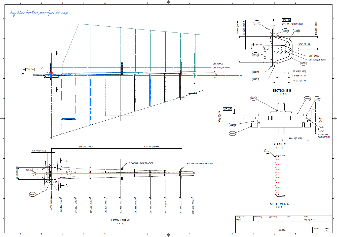
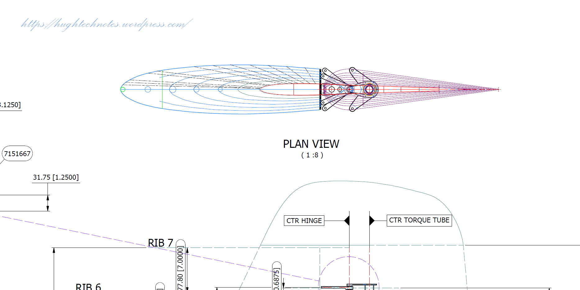
Horizontal Stabiliser & Elevator:
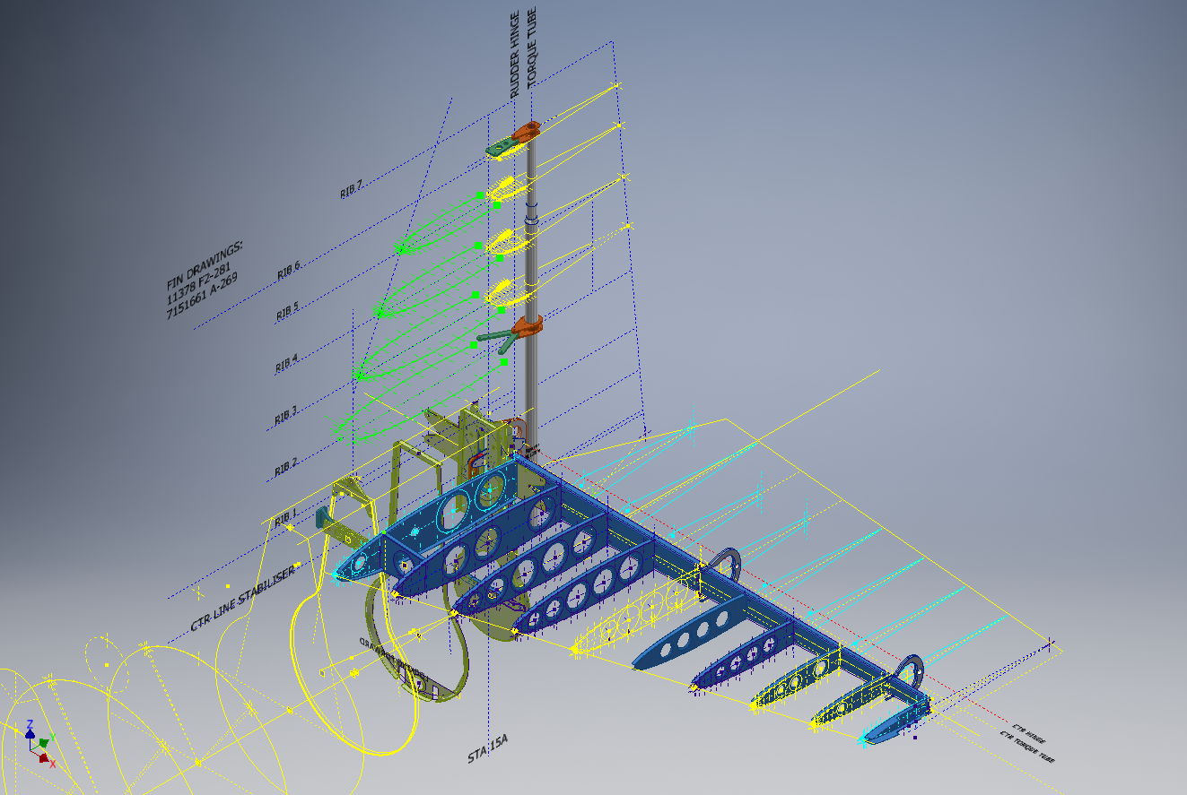
Tail Fin & Rudder:
Fuselage Frame 3:
If you are interested in obtaining my research data for this aircraft then please send me an email. At the moment this is an unfinished project but the available drawings (12) are fully dimensioned which will help you with establishing correct datums and station frame associations along with a few spreadsheets. HughTechnotes@gmail.com
The primary objective of my work is to record an accurate database of ordinate dimensional data for various aircraft fuselage frames, cowls, wings, cockpit, and stabilizers. This database is derived from manufacturers original documents and drawings.
Often the original source documents are poor quality, occasionally almost illegible, but if we have 95% of the ordinates for a frame then it is relatively straightforward using today’s technologies to determining the missing 5%. Where possible I will cross-reference with part drawings or alternative information to verify.
However, most archive records are incomplete, as was my frustration with the F6F Hellcat. Having completed the wings, fuselage, and cowl I was stumped by the apparent lack of ordinate data for the tail and horizontal stabilizers (even from part drawings).
There are 2 approaches to determining the missing information. The first is to model the information you do know; from part files, supporting documentation and 3rd part resources. This may provide enough information to determine the missing geometry in order to extrapolate a dimensional data set.
The second; and I would never do this myself; is to trace or convert the outlines of the components from the scanned drawings. There are several products available that will convert raster images to vector files but first, we must achieve a properly scaled image to work with. Most raster image from these archives are scans from 35mm microfilm and due to the nature of the process, the resulting image will not be equally scalable in both X and Y directions.
Assuming you wish to work with CAD and use this image as a background I would recommend the following process to achieve the best result. This particular drawing is created from actual loft templates and includes the locating pins set to a specified distance in each of the corners plus a drawing scale rule.
Some drawings may only have scale rules, either way, the process is the same.
If we insert this image directly into a drawing in Autocad or similar the only option is a user-defined global scale parameter which will scale the image equally in both X and Y directions, which is not what we want. Even once the image is inserted the option is the same.
The best way to circumvent this is to insert the image into a drawing, without any scale parameters applied. Then save this drawing including the image as a DWG file.
Xref this drawing into another drawing and you will be presented with the following dialogue box ( I am using Draftsight but Autocad will be similar).
As you can see you now have the option to apply different scales to the X and Y directions. This works very well and will provide a very good reference for your work. I should clarify that some CAD products have the option to insert an image as an Xref but the scaling options are not the same as for a DWG file, instead reverts to a global scale option only.
As a workaround for missing information, this is a very accurate way of achieving a good result and will satisfy the majority of applications.
As my projects are records of known dimensional information this process would not be applicable.
I have come across some interesting information that has provided some clarification of the cowl ordinates. This has enabled me to further the progress of the F6F Hellcat project.
I have also verified the fuselage ordinates which I have subsequently updated. This project is now looking rather good with wings, front nose ring, air scoop, cowl and of course the fuselage ordinates now complete.
As you can see some preliminary work has also been done on the tailfin which will be closely followed by the horizontal stabilizers and eventually the canopy.
It is unlikely that there is sufficient information to fully complete the Tailfin and Horizontal stabilisers ordinate datasets due to the lack of dimensional data for the tail components. At this stage, the best I can do is locate the 2d plans for this area and hopefully return to this project at a later date when more information becomes available. It has been a challenge getting this far with the project.
Hellcat Ordinates/CAD datasets.
Now available online; a comprehensive package comprising detailed spreadsheets (mm and inch) with supporting Grumman ordinate blueprints, Autocad DWG and original Inventor assembly and part files. The entire package covers 90% of the aircraft geometry. See previous posts for detailed discussions on the development.
For all enquiries please email me for details at hughtechnotes@gmail.com.

 The original formula for one of the constants “P” is given as shown (1). If we enter the formula as prescribed in a hand calculator it will evaluate correctly but will not work correctly in Excel in this format. So we need to tell Excel to essentially divide everything in the top line by everything in the bottom by adding parenthesis as shown (2).


 Using this font in CAD systems will result in problems with embossing or extruding.


 The full Ordinate/CAD dataset will literally save you 100’s of hours of tedious work and is available online.