I mention in my Bio that I used to indulge in Photography which I got into in the late 70s. In those days it was mainly portraits, fashion and hairstyles…I did okay and had many images published at that time. I ventured into many fields of photography throughout the years; including industrial; which of course was an advantage for me also working as an engineer…I had ready access to exciting material.
Photography though was always a part-time interest, something I was passionate about but not something I pursued commercially after my stint in the late 70 and early 80s (even then only part-time). Actually, when I got married and had kids the focus was entirely on them; which of course was amazing times. I photographed everything and everywhere we went as a family…great memories.
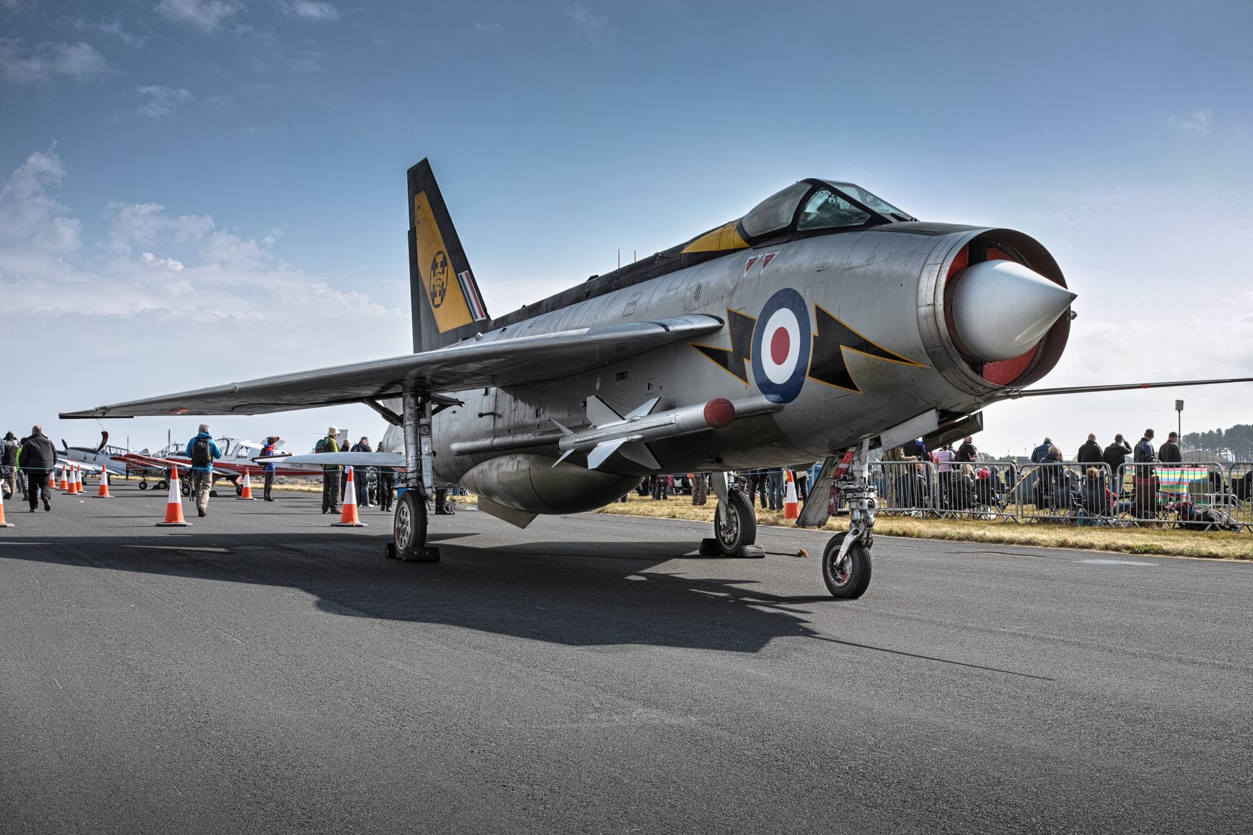
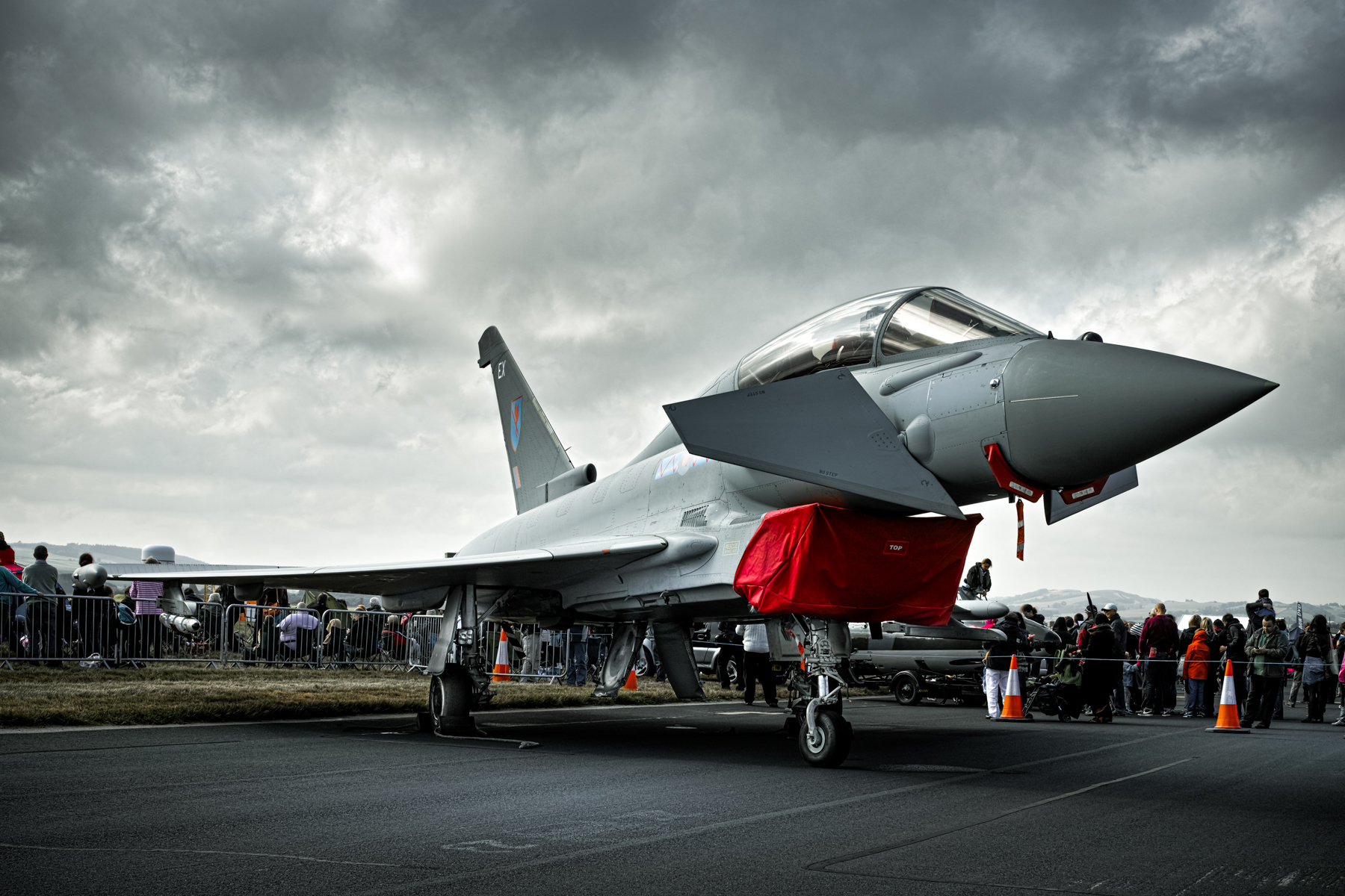
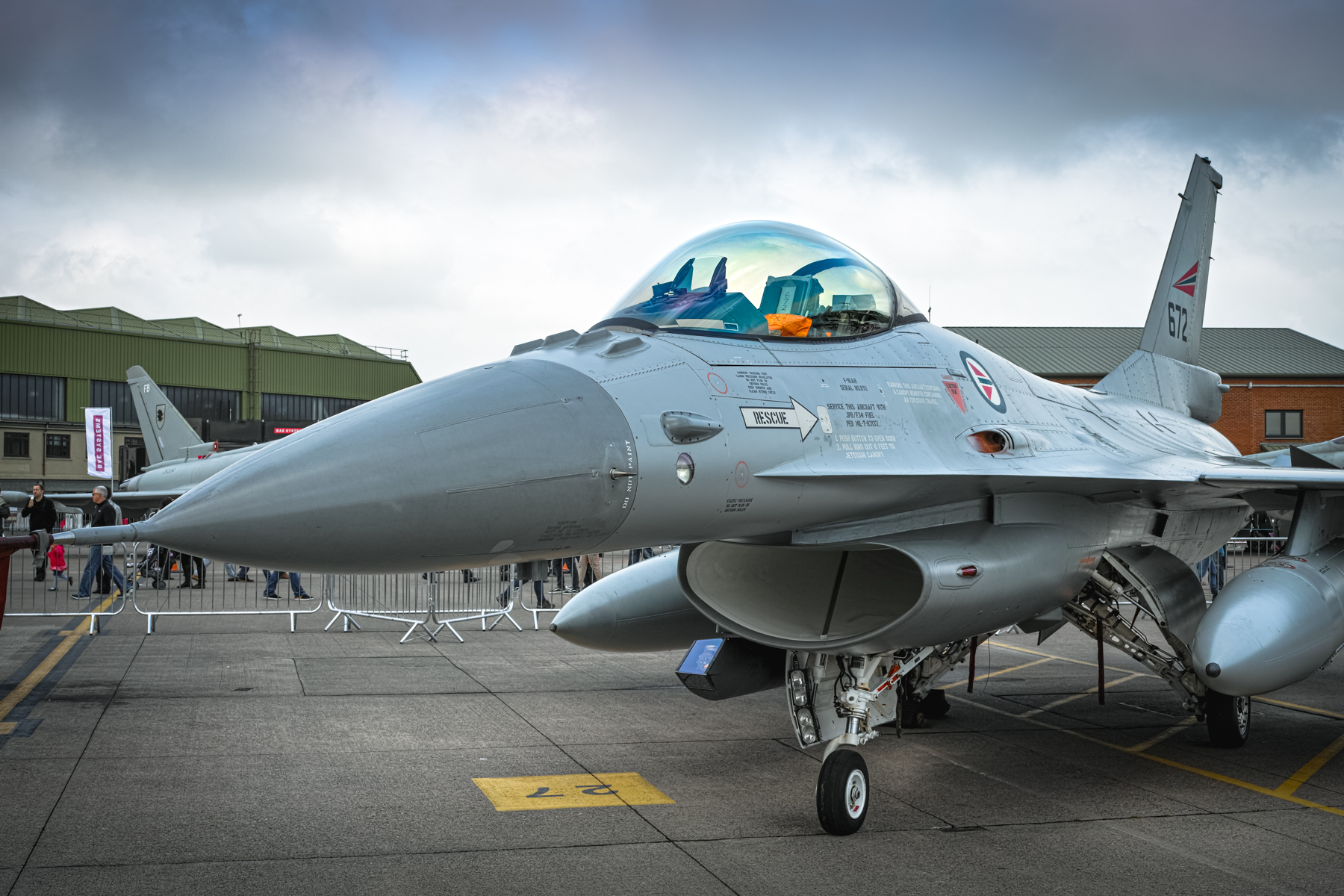
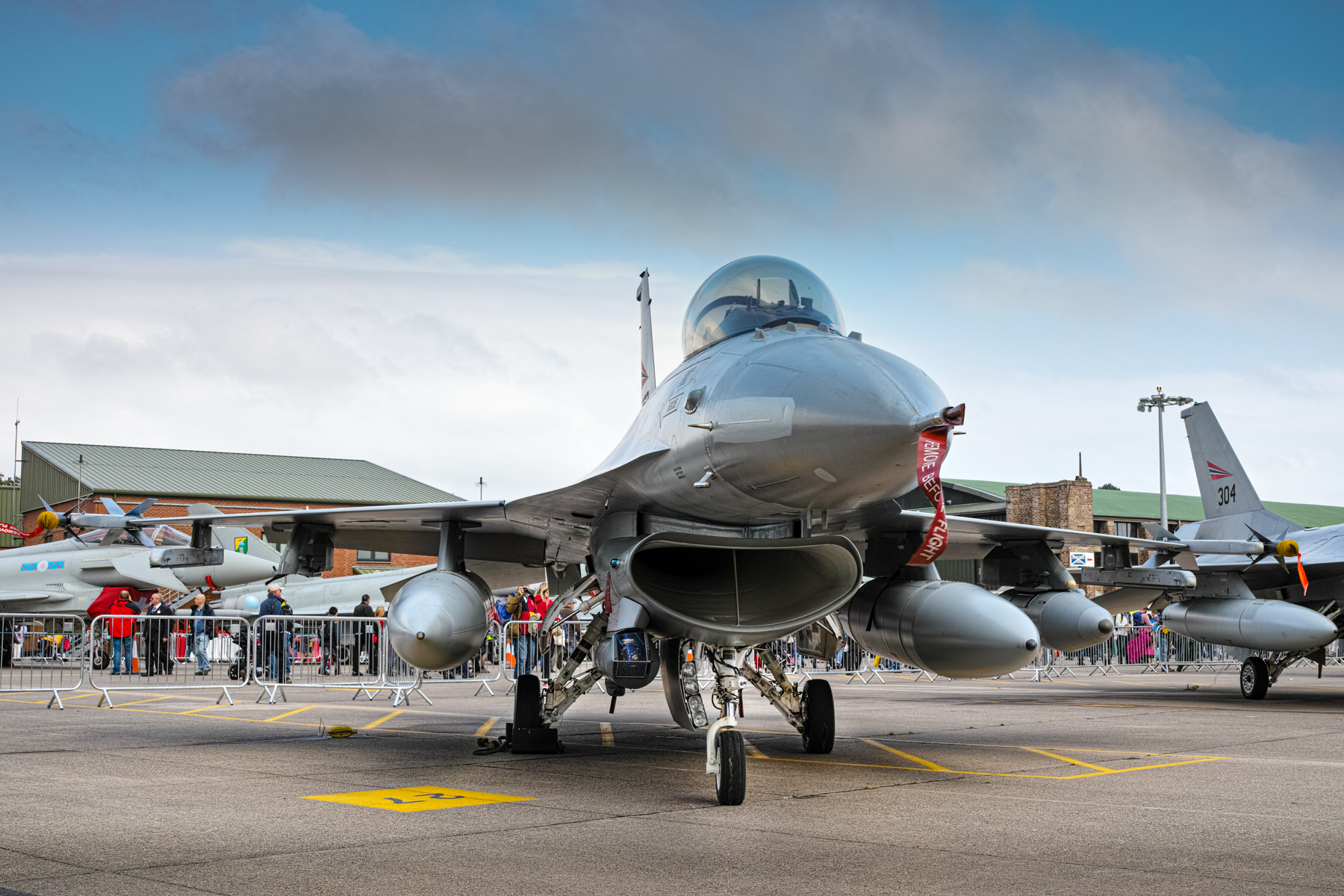
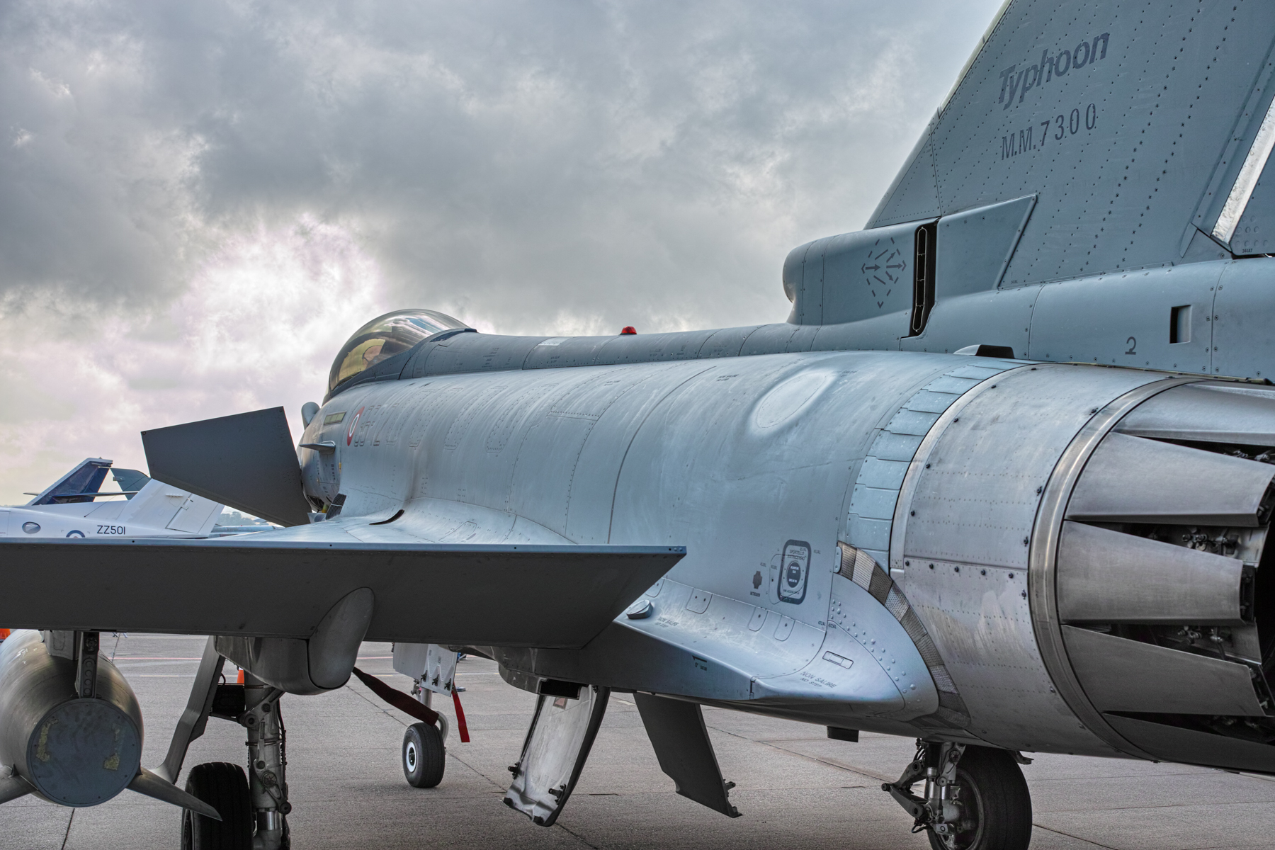
I also enjoy photographing aircraft. These were taken at RAF Leuchars in Fife, Scotland at the last ever International Air show before the base was transferred to the army in 2015. These were all taken with the Sigma DP2M camera…one of the Foveon sensor range of cameras. The Sigma camera was legendary for the incredible detail they could capture, though admittedly they were a real pig to use!
I will look through the archives and process some more and include them in future articles here. I have these online and are available for download here…full-size images (roughly 4704×3136) in Jpg format.
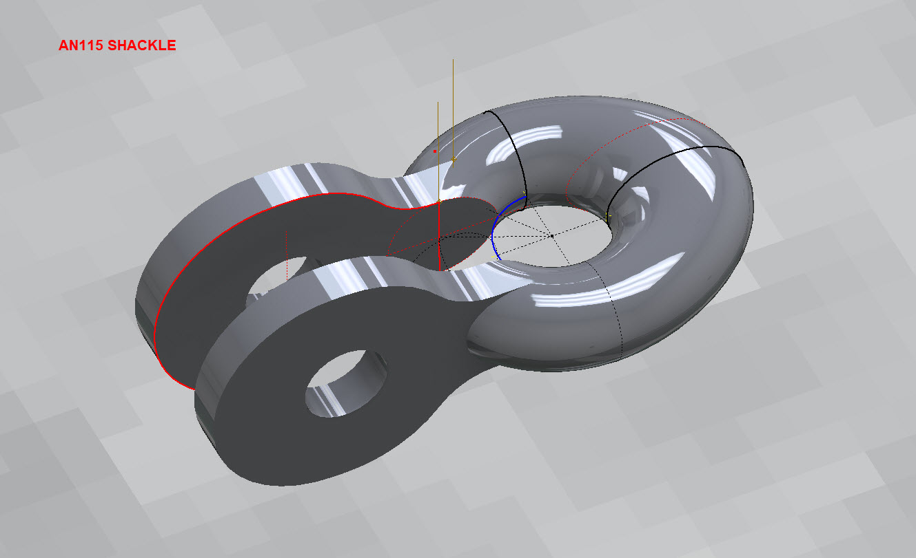
Working my way through the various AN Standard components I thought it may be prudent to write up a quick Technote on modelling the AN115 Shackle.
At first glance, this seems to be a fairly straightforward item to model, however, getting the transition from the flat section to the curved ring is rather tricky. When you view this item on Google and look through the various images of the finished product there are visibly small variations in how this has been interpreted. Needless to say that I have my own interpretation to achieve a smooth integration while ensuring the integrity of the finished model.
First of all, ignore the bulge on the right-hand side…for some part numbers this area is elliptical and not round…so for development reasons I have purposely exaggerated the profile to test the iPart creation.
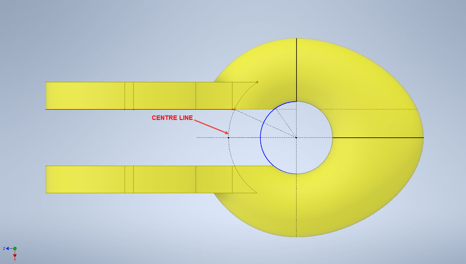
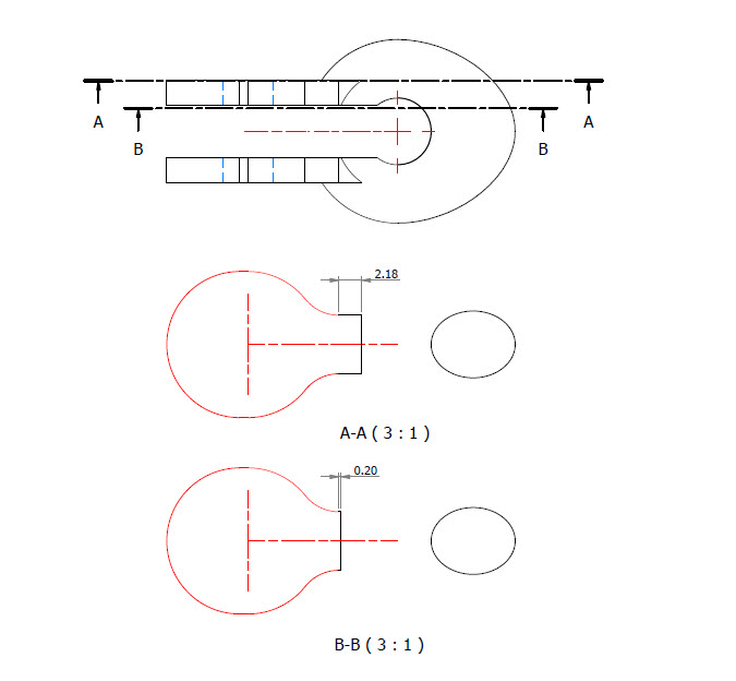
What I was looking for was to achieve a smooth transition along the edges of the flat portion to merge with the round profiles of the ring section. My first attempt was simply to have a curved edge at point “1” that was tangent to the ring and the edge of the flat section. However, that did not achieve a good result because the top and bottom surfaces of the flat section coincide with the ring at different points which created a small twist when lofting the sketch profiles.
I found the best way of solving this was to introduce a small horizontal line tangent to the ring section profiles. For the inner sketch, this was only 0.2mm which translates to just over 2mm for the outer sketch. The points shown as “1” and “2” are the centre points projected from the ring centre line which is the start point for those sketched horizontal lines.
Now when we loft the 2 sketches we have a good square edge for the flat section…by the way, I should note that the flat section is initially lofted as a separate solid because we still have one step to do before we merge the solids into one. After lofting the flat sketches we still have to trim the resulting solid to follow the centre of the ring surface.
This is simply done by extruding a surface from the centre line of the ring as shown and then trim back the excess from the flat section model. Now we merge the 2 solids and we end up with a shackle that has a smooth transition from flat to ring without any twists or surface anomalies.
The bulge is still there on the final image…that will be gone once I finish filling out the table with the various part number dimensions.
So sometimes when you are modelling a complex item like this it often helps to introduce a minor feature (in this case a small 0.2mm line) to ensure that lofting and extrusion activities provide the desired end results.
AN481 Clevis Rod End:
Another tricky item to model is the AN481 Clevis Rod End. There are 4 variations on the same model that comprise 2 sets each with a narrow gap and a wide gap. Technically it is possible to create all variations in one part file and use Suppress and Unsuppress options to exclude or include features…however, I decided not to do that because it can be a real pain adapting the model if the regeneration does not quite work the way one expects it to. The model is not that complicated so it was just as easy and to be honest much tidier to create separate part files for each variation.
As usual for further information please get in touch at Hughtechnotes@gmail.com
AN116 Shackle:
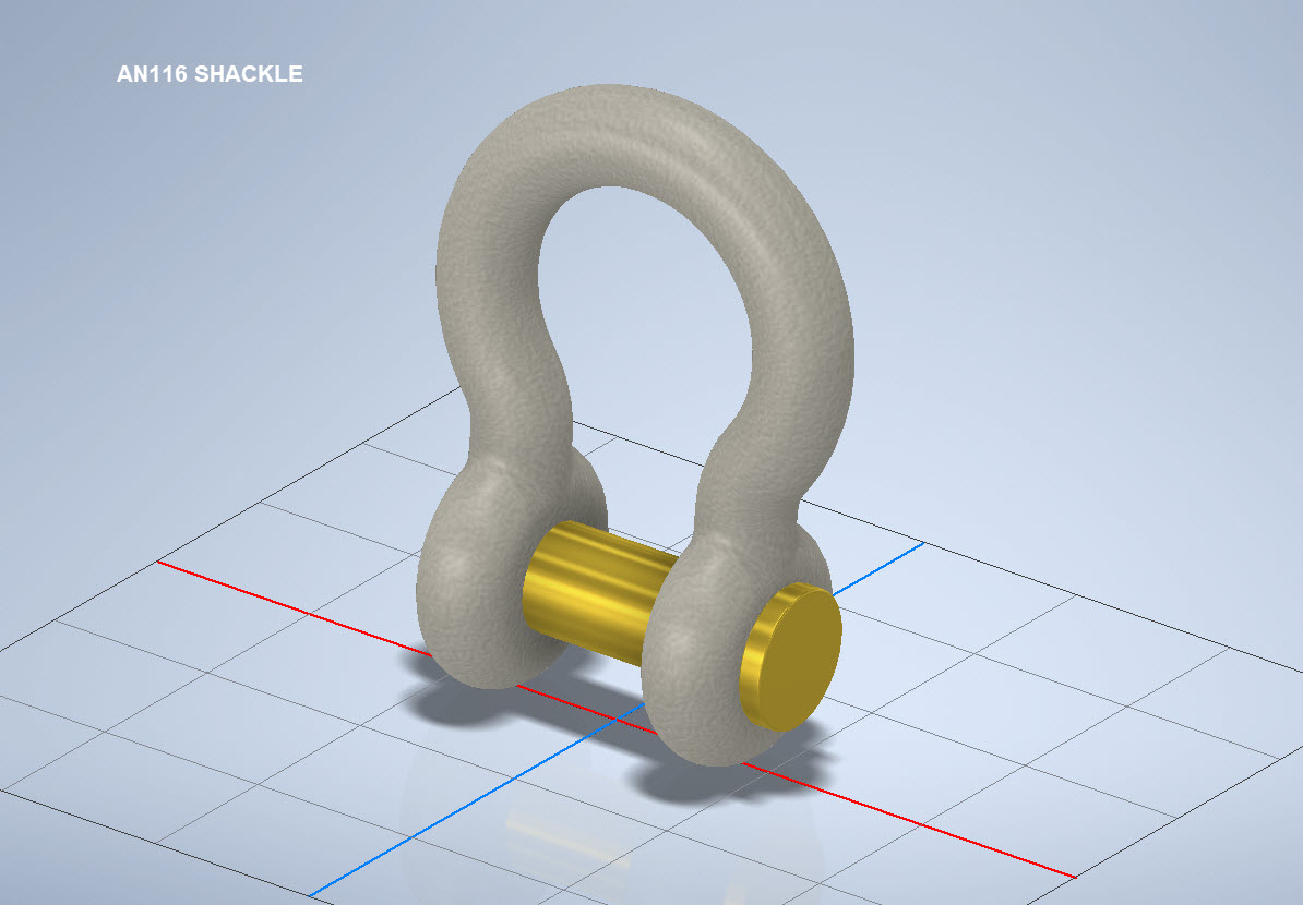
The AN116 Shackle PIn is shown with a rounded head which I decided not to model due to the lack of detailed information for this pin. I tend to shy away from modelling components where there are no specific dimensions. I am not sure this is critical except where accessibility for tightening the pin is a consideration.
The new Parts Library should be finished at the end of August…I will advise.
Many moons ago I started a project to develop libraries of Aeronautical standard parts according to the various National and International standards pertinent to aircraft design and maintenance noted in this article.
Using the original standards from the wartime era and the updated, often replacement standards, I figured it would be a good idea to develop this project further. I am aware that there are many different CAD systems so it would be folly to just develop this for just one product.
The above products are currently available in the Resources Tab of this blog and though included with the Mustang P-51 Ordinate/CAD dataset are standard for many aircraft of this era and accordingly are available separately. This existing collection is already very comprehensive with over 300 parts modelled and listed, though these are in line for an overhaul and update.
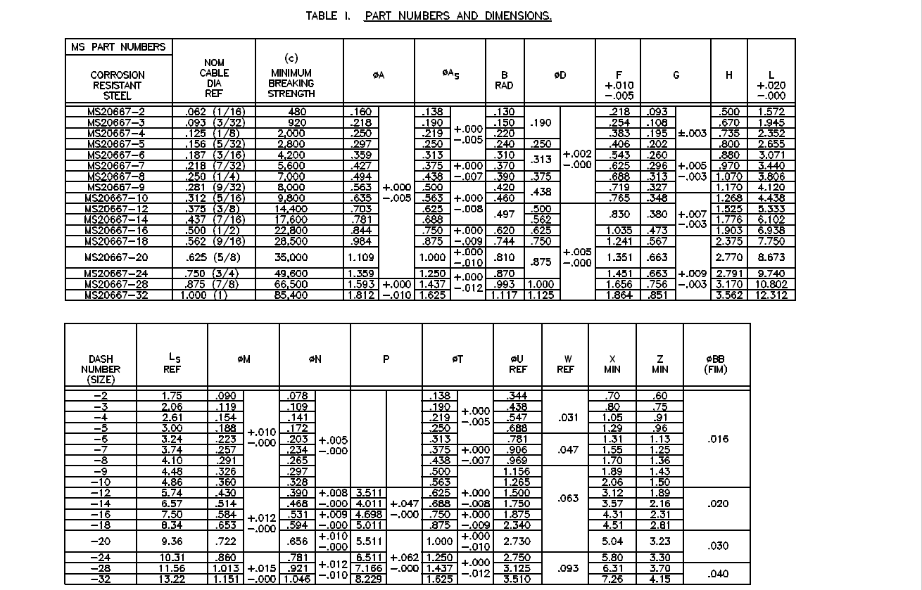
Moving forward with this project I will develop the configuration spreadsheets exactly as per the original specification tables set out plus any additional dimensional data that will be required for modelling. This will be accompanied by a DWG file as a template to use when developing your own equivalent of an iPart. Essentially putting together a dataset that anyone can use regardless of what CAD system they are using.
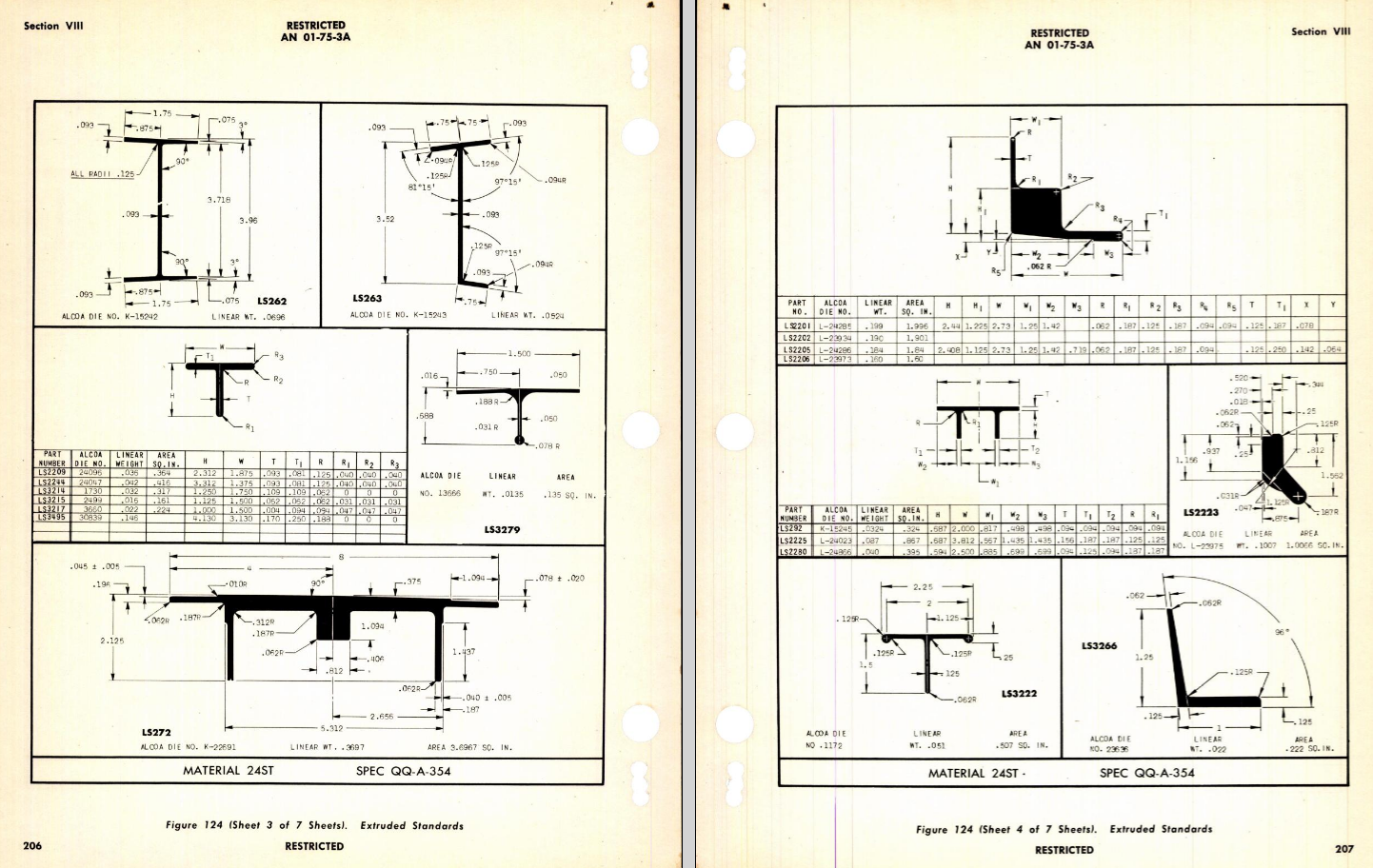
Additionally, standard metal work profiles will also be developed and produced in a similar manner.
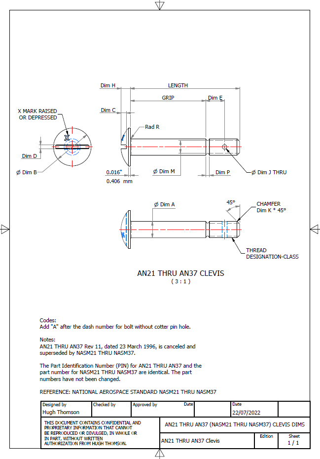
There is a catch: This will take a while to do and probably won’t be ready until October. Typically the study will comprise a basic dimensioned drawing exactly as per the reference Standard with accompanying spreadsheets. There will be separate spreadsheets for each part number in a collective Standard, though there may be only one drawing. For example AN21 THRU AN37.
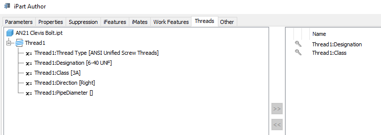
The way to use this dataset; regardless of the CAD system; is to first develop the part model naming the parameters as defined in the spec (you can use the DWG for your sketch template). In this example, the first 2 columns are generic to the specific CAD system with the first column being a unique value. From LENGTH to Dim P, in the table, these are the main geometry parameters. The Hole1 column has values “Suppress” or “Compute” which is an instruction to exclude or include the hole. The Thread parameters are defined as a Designation and Class which are standard integral parameters; those names may vary accordingly. Typically in Inventor, they can be found in the iParts Author as follows:
Once you have your Part modelled, open the iParts author and set up the first line of the table…you just need the first line at this stage Close the Author and open the table in Excel and copy the contents of the provided spreadsheet data tables above… ignore the header/titles. The iPart table will now be updated with all the above variations. It does not matter if your part template is Metric or Inches as the part dimensions are predefined as inches and will automatically recalculate depending on your template standards. You can of course already do this with the existing iParts but they are not inclusive of dimensioned drawings…so you have a bit more work to do referencing the actual standards for parameter names. That’s what this project work is designed to do…essentially finish with full documentation.
These spreadsheets and CAD profiles will enable anyone to very quickly develop a standard library in their own CAD system…an important resource and time-saving endeavour. I should note the actual AN and MS standards are available online for anyone that wants to access them. I have provided a link below to my previous article on this subject.
Blimey, this is quite an awesome task…I envy those that build the standard libraries in the many CAD systems that contain thousands of parts…this will definitely take a long time.
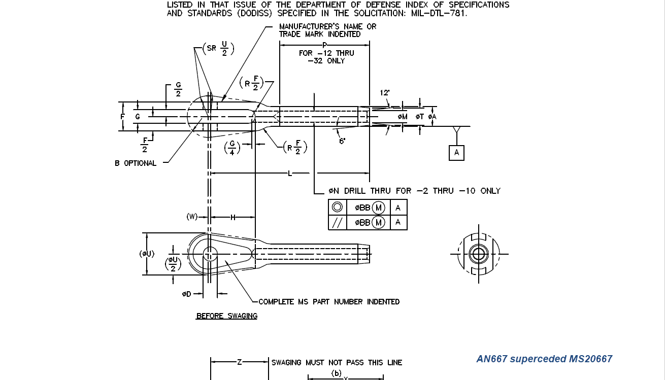
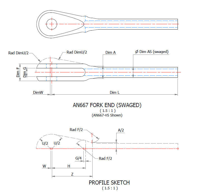
Many of the parts are relatively straightforward like Bolts, Castle Nuts, Clevis Pins etc that require nothing more than basic dimensioned drawings. Occasionally though many parts will require additional sketches to clarify the profiles, like this AN667 Terminal Fork End. Also in similar cases, the model will be dimensioned to As-Fitted/Swaged for use in assemblies. You can basically ignore the Scale as all the DWG versions of these drawings will be 1:1 according to the part number actually modelled.
This is a list of the Specifications I am currently working on. Many of these are updated versions of the existing standards available on the CAD Resources page. The updates include marginal improvements to the 3d models, additional data and verification of listed dimensions. The data sets also include dual part numbers where an item has been updated to a newer standard the new designation is noted alongside the old.
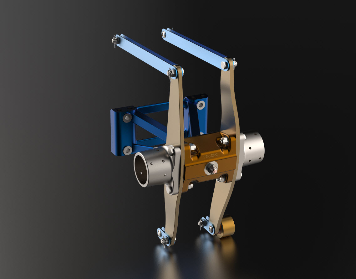
It is very important to get this stuff right, to ensure the part designations and representations are correctly defined in the assemblies. Have you ever tried to figure out assembly configurations from the NAA assembly drawings or picked your way through the Parts catalog just to identify a single connection for a clevis, nut and bolt, turnbuckle or whatever…it is time intensive. It was this desire to bring clarity to these assemblies that I created the P-51 Mustang cad models shown below, which incidentally was the catalyst that drove the development of these Part libraries.
Get in touch with any inquiries at the usual email. hughtechnotes@gmail.com
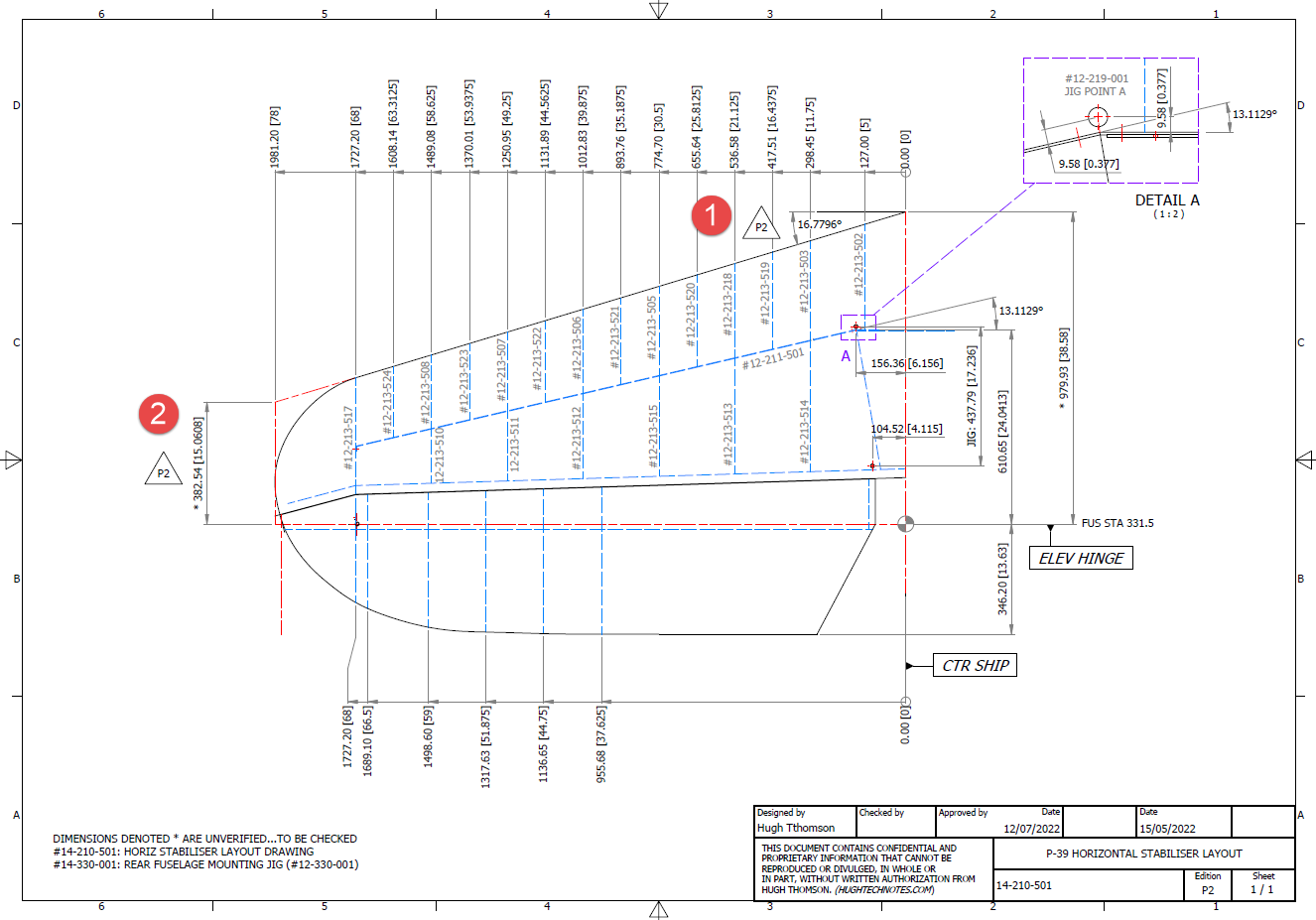
In a previous post, I covered the significant new model for P-39 Airacobra. This model is fully inclusive of all aspects of the aircraft. Within this post, I mentioned the extensive study involved in determining the layout for the Horizontal Stabiliser; the dimensions of which were unclear in the available blueprints
I was particularly keen to establish verification for the leading edge angle and though I had written to a number of organisations that have the P-39; surprisingly none of them took the time to either acknowledge or indeed reply…which of course was disappointing. From my experience, the industry is normally very supportive with regard to technical inquiries.
I revisited the documentation I do have and established that relevant information was included in the NACA Wartime Report L-602 which gives the chord length at Sta 49.25. It turns out; from my initial assessment; that the dimension at “2” was barely 2mm out and the Leading Edge angle is now 16.7796 degrees.
I mentioned in my last post that this latest study is available now which also includes the original model; which was more of a 3D modelling exercise than a dimensional study.
The P-39 Airacobra new CAD/Ordinate study is an impressive project.
All inquiries as usual to; hughtechnotes@gmail.com
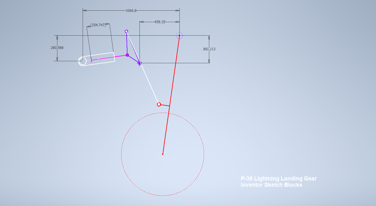
I have uploaded a video showing the mechanism for the Main Landing Gear for the Lockheed P-38 Lightning. This was created using the Inventor Sketch block feature which is a great tool to understand how these mechanisms work and provides an opportunity to examine the operational relationships.
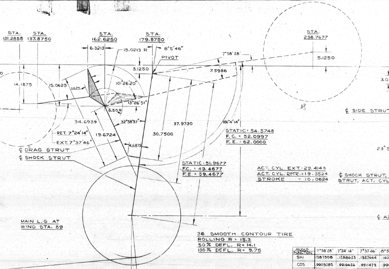
Landing Gear mechanisms are quite complex and at first glance at the drawings, it can be difficult to fathom how they actually work. One way of visualising this mechanism and understanding the extent of the operation is to use Sketch Blocks.
The way this works is that you first build your sketch; minimise constraints, and select the elements that form each of the components; whether that be hydraulic cylinders, linkages, axles etc. Then you would constrain them according to how the mechanism should work…in this example, the cylinder actuator rod is constrained to align with the centre of the cylinder and virtually everything else is concentric constraints at each of the nodes. There are a number of good Youtube videos that show how this is done.
The dimension shown is a “driven” dimension which will change according to the location of the operation. You could of course have driven dimensions for the angles to check the max and minimum inclination. The quality of the video is not great but you get the idea.
For better precision, it is always best to use the Simulation environment with relative constraints applied accordingly to confirm operational parameters but for a quick check on movement, the Sketch Block feature is a good solution prior to committing to modelling.
Update 16th June 2022 LG Hinges:
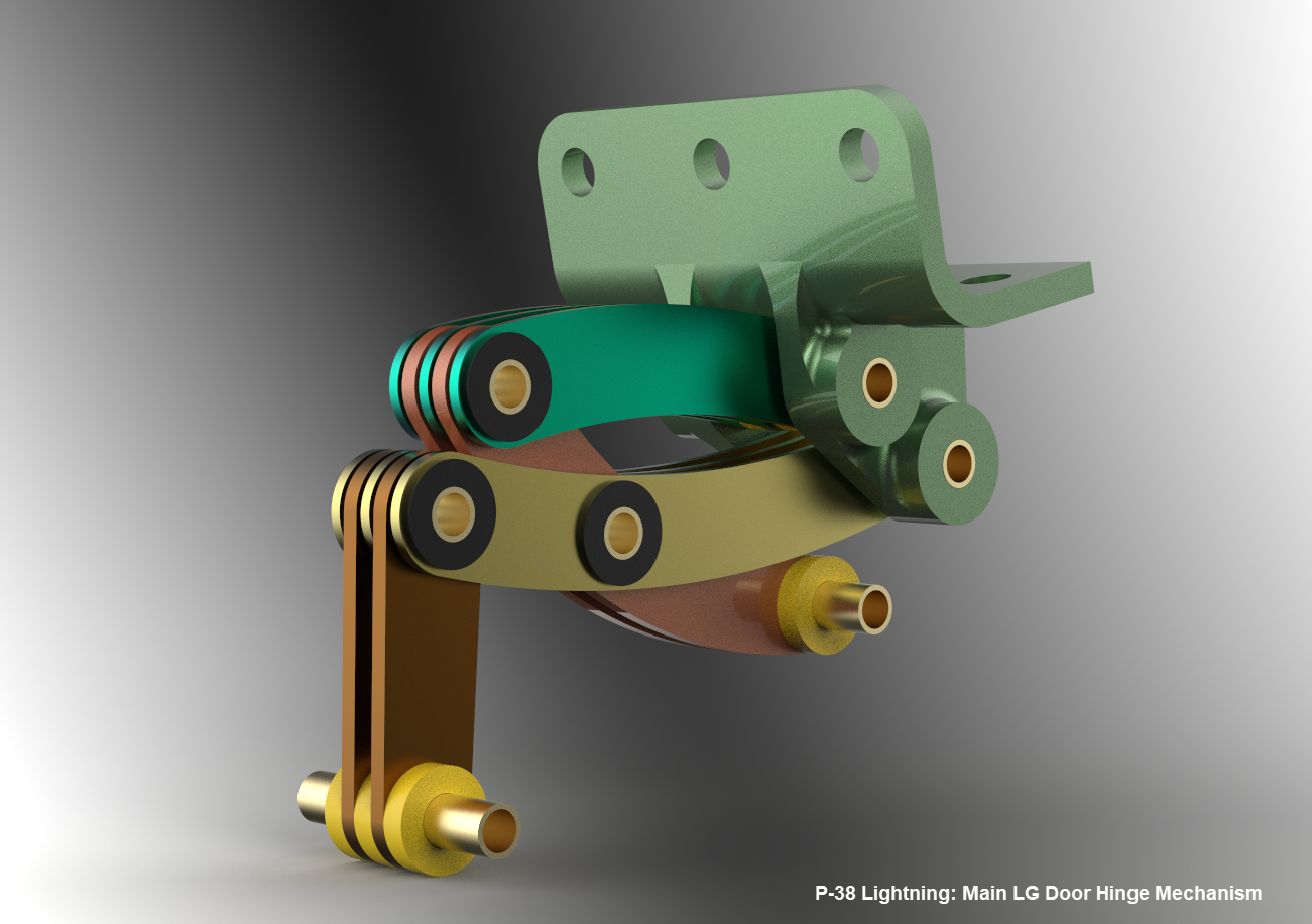
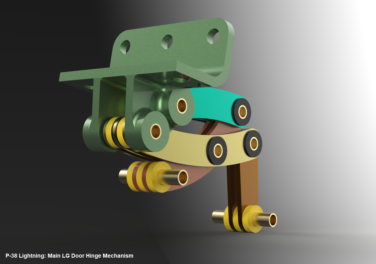
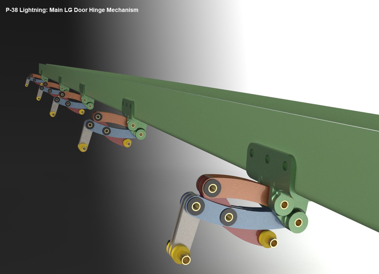
Have you ever wondered what the Main Landing Gear Door Hinges look like?…
When I started this project the Lockheed drawings seemed to be quite well organised with the provision of a number of what I thought were key ordinate drawings. These appeared to be full of tabulated dimensions and associated formulas. The wing layout and dimensional information were well documented so it was logical to assume this pattern would follow with the other drawings. Unfortunately, this was not to be the case with the Empennage drawings which required a lot more work thus this blog article.
Having worked my way through the vagaries of the wing design and the forward Boom section I then progressed to the Vertical Stabiliser Fin and Rudder drawings. The first drawing in the batch I looked at was an ordinate layout drawing which on closer inspection only provided the location of the spars and struts…there was no information on the Leading or Trailing edge curved profiles. So I ventured to look at Assembly drawing #223026 to see what information I could glean from that.
Again it was just the main component locations and little or no information on the curvature. However, there was the drawing for the Rudder Tab and yes indeed it did contain information on the curvature. At this point, I should note that the Lockheed drawings include some sketches which contain chord profile information for both the wings and empennage…unfortunately 80% of those are illegible.
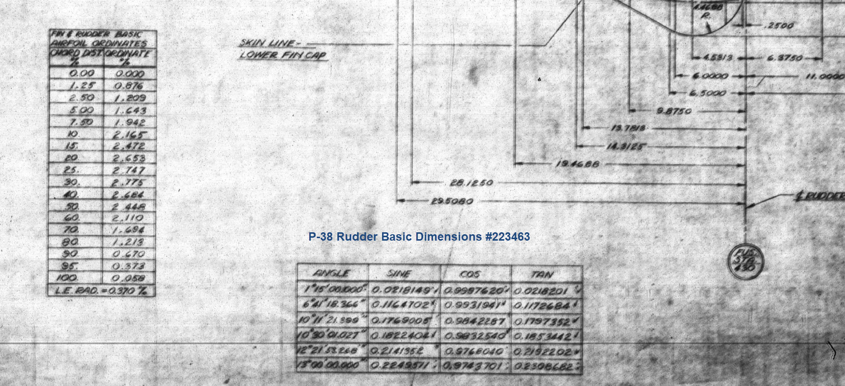
This sketch is the exception for the Fin/Rudder profiles at a specified WaterLine. This is where things got interesting because the chord dimension on this drawing did not match the dimension of the Rudder Tab at the same location after I had modelled it and furthermore did not match a comparative drawing in the Structural manual which also included dimensional information. It turns out that the Rudder and Tab Trailing edges are constructed in the same way as the main wing with an extended tab for jointing top and bottom sheet panels…which explains the dimensional variation.
The dimensions on the Basic layout sketch above and the corresponding information in the structural repair manual are actually relative to the rib chord and not to the finished edge.
As the above sketch was the only legible example of the requisite rib chord information I had to rethink my approach and reverse engineer the data on the Fin/Rudder’s ribs.
The Fin/Rudder rib drawings contain chord profiles for the ribs, though only partial I suspected that they may follow a standard format normally applied to rib airfoils i.e. percentage increments. It may seem an obvious comparison but in my experience, this is not always the case.
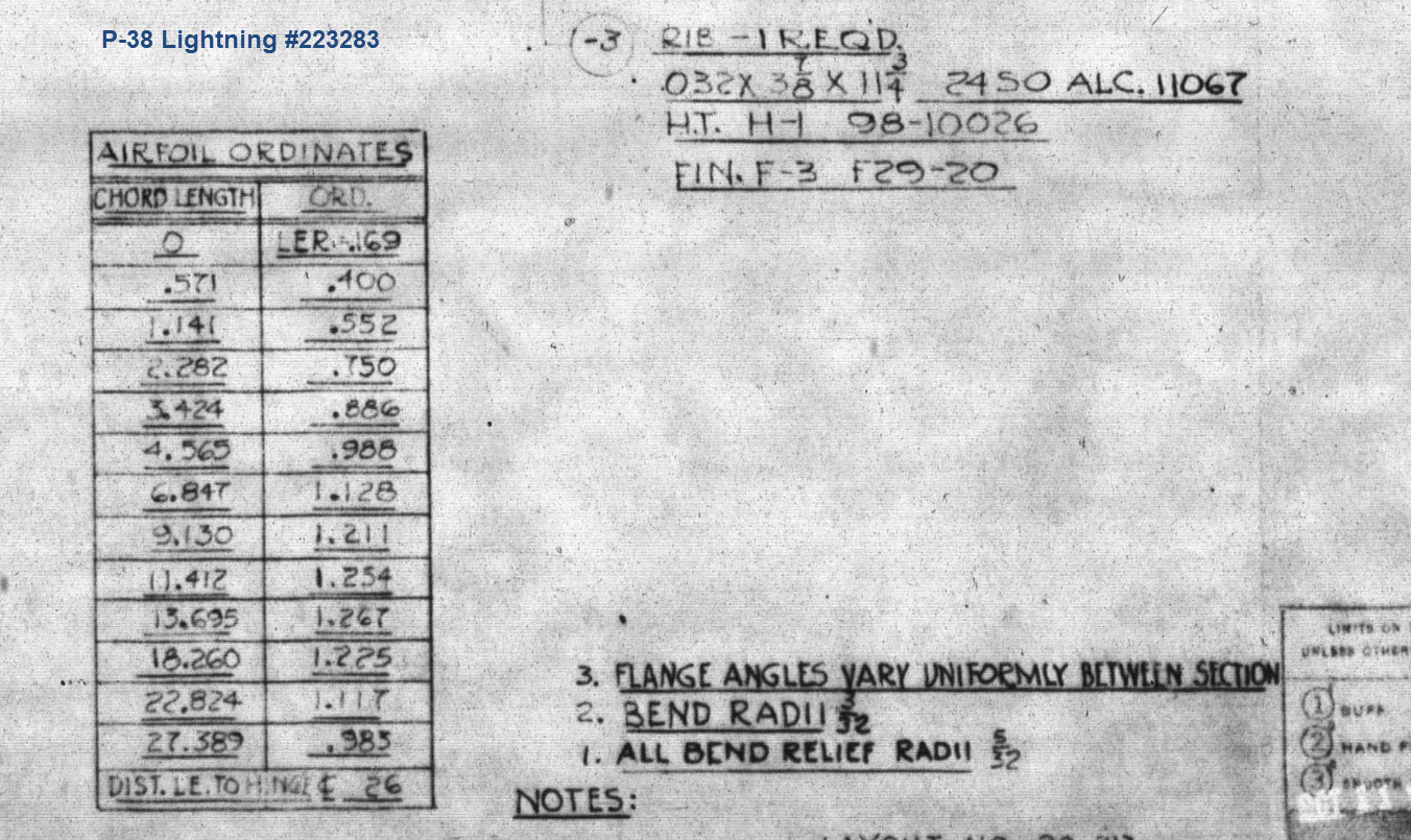
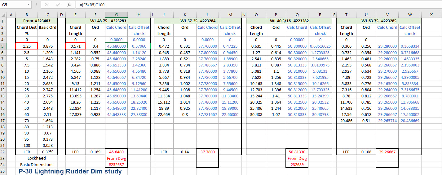
The drawing on the left is the partial profile information for the Fin/Rudder rib and the drawing on the right is the basic profile included on the Ordinate layout drawing I mentioned in the beginning. I surmised that if the Rib drawing follows the same convention as the Ordinate table with logical percentage increments it would be possible to determine the chord lengths of each rib.
In excel I created this spreadsheet with the Ordinate Table on the left and subsequent tables containing information from the Fin/Rudder Rib drawings. The first 2 columns in each table are the values as noted on the drawings and then to check my theory that they followed a logical sequence I calculated the third column which indeed returned a close approximation of the actual chord length. The fourth column is the new offsets calculated from the derived chord length in each case.
Having established that the rib profile is as I expected it is now possible to create ordinate points to profile the Trailing Edge and define the contours for the Rudder’s ribs. Remember we also have a tab extension to which we have to add an additional fraction of an inch to get the final trimmed profile. As I am calculating and applying the new information to the CAD model sketches I maintain a 2d view to check the overall dimensions to see how they compare.
I am only halfway through the development of the Fin and Rudder layout as shown but will continue the same process to ascertain the remaining curve sections. At the end of the day and similarly the same with the wing the 2d drawing will display 2 lines profiling the Trailing Edge, one which will be the 100% chord ordinate and the other the extended tab. By the way please don’t use any of the dimensions noted on this drawing…it is a study with temporary dimensions!
A lot of work still to do on this which will have to be done for all the spars and ribs to ascertain the correct curvatures of the Trailing Edges. Where occasionally you need to derive specific information it is often beneficial to look at opportunities to interrogate what information you do have to determine the information you need.
Update 26th May 2022:
After extensive study and listing of ordinates in stacks of excel tables, I have managed to verify the Vertical Stabiliser dimensions. The Basic or True Rudder line noted on the sheet drawings is defined by the 100% chord dimension for the ribs…this is an important change to the wing trailing edge. Anyway as I need to take a break I thought it may be prudent to provide this update for your perusal. Still some work to do for the top and bottom profiles and of course a general tidy up would be in order…it is still a work in progress!
I could have just accepted the dimensions noted in the Structural repair manual as the end result would have been close. However, it is important where there are slight variations between the manual, the ordinate sketch and the part drawings that every effort is expended to understand the design intent and derive a correct solution.
One further point of interest: the profile for the Vertical Stabilizer is close to being symmetrical about the vertical centre of the full length of the rib chords. I marked out the centres of each rib profile and found only a 3.6mm difference for the top section, however, the variation in the lower section (below WL 21) is considerably more at 19mm… which is too much even accounting for the fractional accuracy from inch measurements.
Update 10th July 2022:
My study of the P-38 Lightning is now finished. I have documented all aspects of the aircraft and compiled an extensive record of dimensions in a comprehensive Excel spreadsheet. The 3d CAD model is supported with dimensioned 2d layout drawings with all models available in native IPT, IAM forms as well as Parasolid XT and 3d DWG.
For more information get in touch, as usual, contact me at hughtechnotes@gmail.com
I can obtain a small number of key dimensions from the panel drawings which will not be enough to achieve an accurate full profile. I do hope someone has a copy.
I have tried all the usual sources for this information without success.
I can’t offer you much for the drawings but I am willing to share the comprehensive ordinate study and cad material when this project is complete.
Further Request: Photos of Wing Tip Required:
The wingtip trailing edge has a tab extension as a consequence of the connection of the top and lower panels. I am curious as to how this extension integrates at the extreme tip of the wing. If anyone has any close-up photos for the wing tip I sure would appreciate a copy.
Let me know if you can help. Email hughtechnotes@gmail.com
Update: 21st May 2022:
I have not had much luck with sourcing the above material. The Mold drawings would certainly have been enormously helpful in determining an accurate ordinate model. There is a Plan B, though it is going to be a fairly intensive search for every morsel of information that can be gleaned from the individual part drawings, manuals and reports that collectively will give me enough to achieve an accurate definition of the FWD Boom and Engine cowl surfaces.
An example would be the Scoop web plate profiles shown above to achieve some surface definition in those areas. I am currently working on the Landing Gear doors which will help define the lower surfaces. This is a lot of work which unfortunately means this will not be ready until much later in the year. I don’t do guesswork, if the ordinate point does not exist it is not on the model.
If anyone has any information that can assist me with these ordinate points, please, please do get in touch.
Recycling Project: Repurpose Construction Site Waste.
I haven’t posted for a while due to research for a number of environmental and recycling projects. The projects involve researching design options to see how we can repurpose/recycle Construction Waste materials like timber, insulation, paper etc.
This post is just to let everyone know that I am still here and working away in the background and also as an introduction to my new project. Aviation projects of course are still work in progress.
Anyway getting back on subject: The Recycling or Upcycling project is based on maximising usage of material that would otherwise not be considered for alternative purpoes. As the typical timber waste from sites vary considerably it is critical for the new designs to be able to utilise the smallest offcuts that would not otherwise be a consideration.
I can’t go into too much detail right now but the essential elements will comprise unique lattice structural forms as well as composite design features to maximise strength and practicality. Historically, recycling construction waste is actually fairly common however it is mostly restricted to creating furniture and small garden utilities. The principal idea of repurposing for garden buildings or offices is not so common due to the technical challenges of effective use of small sized materials…until now.
I plan to crowdfund the construction of a number of these designs shortly. If anyone is interested in supporting these projects please drop me a line.
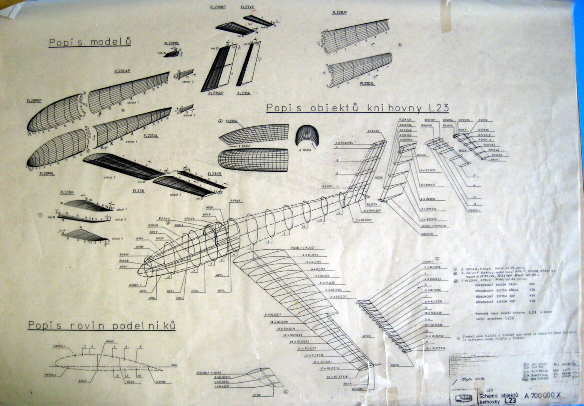
The Work in Progress aviation projects include datasets for the L23 and L33 gliders…watch this space.
“SIMFEROPOL, September 25. / TASS /. An expedition of the Russian Geographical Society (RGO), together with the Russian Ministry of Defense, lifted a Bell P-39 Airacobra fighter from the bottom of the Black Sea from the regiment that took part in the air cover of the Yalta conference of leaders of the anti-Hitler coalition in 1945, a specialist from the Expeditionary Center of the Ministry of Defense Anatoly told TASS on Friday Kalemberg.”
As many of you know I am a huge fan of the P-39 Airacobra. So I was particularly interested to read these reports of the recovery of this P-39 from the Black Sea. These are the links to the articles I have read so far from various news publications.
If anyone has any further information to share on this project please drop me a line and I will feature updates in future articles; perhaps even progress on the restoration.
I have run this blog for almost a decade now in order to pass on and share my research and technical know-how related to the amazing designs of historical aircraft.
The blog is a journal to document my experiences on this journey with articles on the various aircraft designs interspersed with a bunch of Technotes. There’s a lot of stuff so I thought it may be prudent to compile a list of the more popular technotes to date:
Technote Sopwith Pup: Spar Clip Technote: An article discussing some of the design vagaries for the Sopwith Camel as well as in-depth use of sheet metal development.
Other Blog: Pioneering modular workflow and design solutions for use of 3D CAD in Substation design for the Power Industry that defied “expert” optinion. Prior to my work on this subject there was no viable solution for this industry. This was a long time ago but much of the subject matter is still pertinent to the industry today.
Theres a bundle of other interesting stuff and discussions on CAD, design as well as a number of articles on Excel.
I came across a site that provided a link to this blog describing it as a “guy that does CAD from aviation blueprints”. Actually they could not be more wrong. Sure there is a stack of CAD related stuff but the serious work is researching and compiling accurate dimensional data. Did you know for example that the top of the rear fuselage for the P-51D Mustang has only 4 verifiable ordinate points…prior to my documenting this no one actually knew this. The ordinates came from blueprints, reports, manuals and letter correspondence..the latter consumed a lot of time. I am probably only one of a handful of people who has actually studied every single drawing in the P-51 Mustang archive. This is serious research not just CAD!