Technote: P-38 Lightning Tailfin Rudder Calcs

Technote: P-38 Lightning Tailfin Rudder Calcs

When I started this project the Lockheed drawings seemed to be quite well organised with the provision of a number of what I thought were key ordinate drawings. These appeared to be full of tabulated dimensions and associated formulas. The wing layout and dimensional information were well documented so it was logical to assume this pattern would follow with the other drawings. Unfortunately, this was not to be the case with the Empennage drawings which required a lot more work thus this blog article.

Having worked my way through the vagaries of the wing design and the forward Boom section I then progressed to the Vertical Stabiliser Fin and Rudder drawings. The first drawing in the batch I looked at was an ordinate layout drawing which on closer inspection only provided the location of the spars and struts…there was no information on the Leading or Trailing edge curved profiles. So I ventured to look at Assembly drawing #223026 to see what information I could glean from that.

Again it was just the main component locations and little or no information on the curvature. However, there was the drawing for the Rudder Tab and yes indeed it did contain information on the curvature. At this point, I should note that the Lockheed drawings include some sketches which contain chord profile information for both the wings and empennage…unfortunately 80% of those are illegible.

This sketch is the exception for the Fin/Rudder profiles at a specified WaterLine. This is where things got interesting because the chord dimension on this drawing did not match the dimension of the Rudder Tab at the same location after I had modelled it and furthermore did not match a comparative drawing in the Structural manual which also included dimensional information. It turns out that the Rudder and Tab Trailing edges are constructed in the same way as the main wing with an extended tab for jointing top and bottom sheet panels…which explains the dimensional variation.

The dimensions on the Basic layout sketch above and the corresponding information in the structural repair manual are actually relative to the rib chord and not to the finished edge.

As the above sketch was the only legible example of the requisite rib chord information I had to rethink my approach and reverse engineer the data on the Fin/Rudder’s ribs.

The Fin/Rudder rib drawings contain chord profiles for the ribs, though only partial I suspected that they may follow a standard format normally applied to rib airfoils i.e. percentage increments. It may seem an obvious comparison but in my experience, this is not always the case.

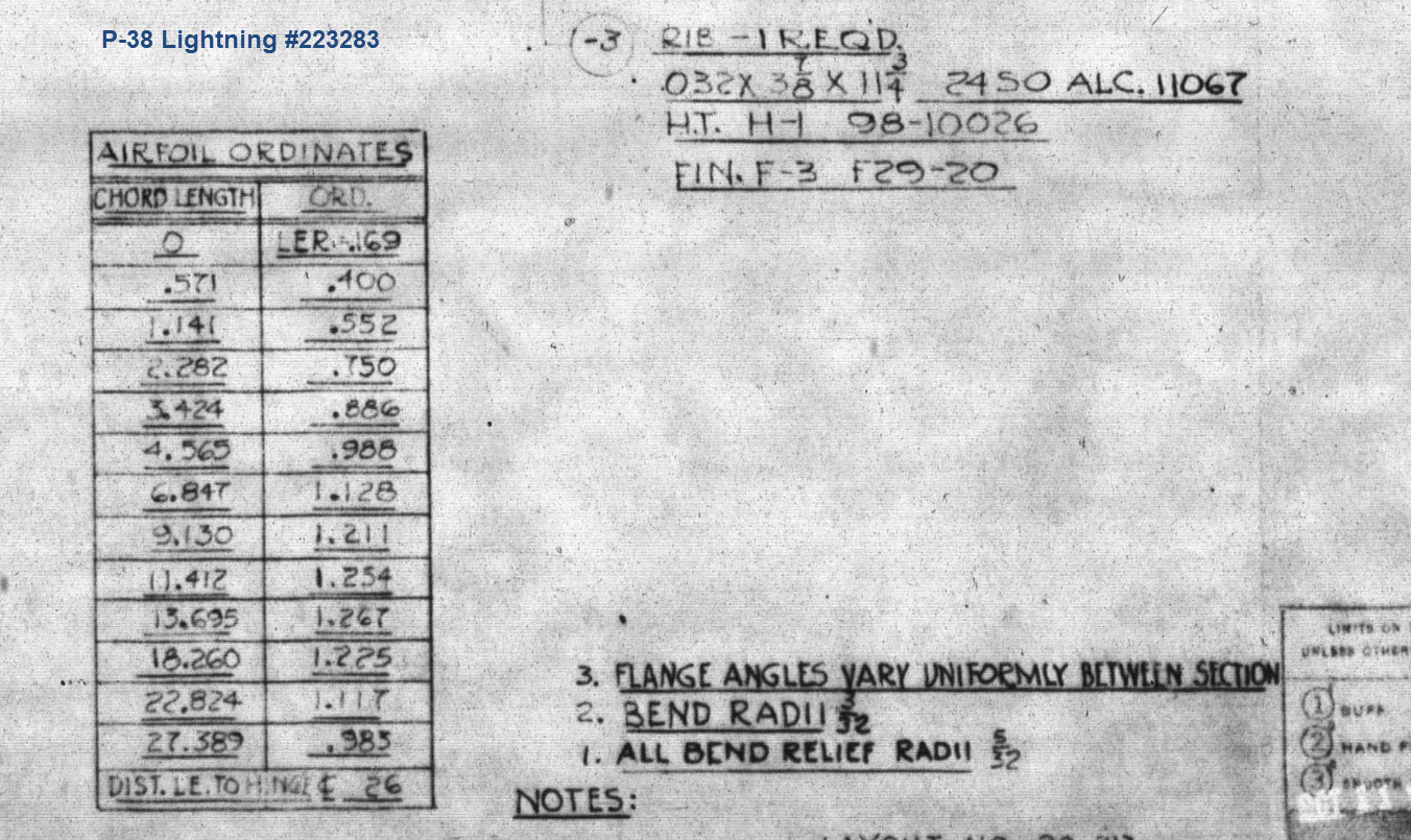
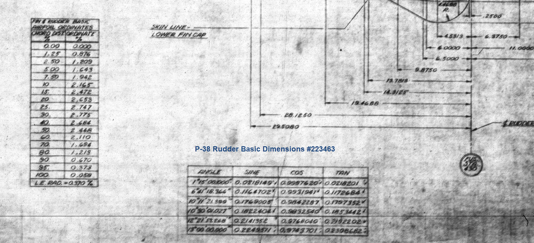
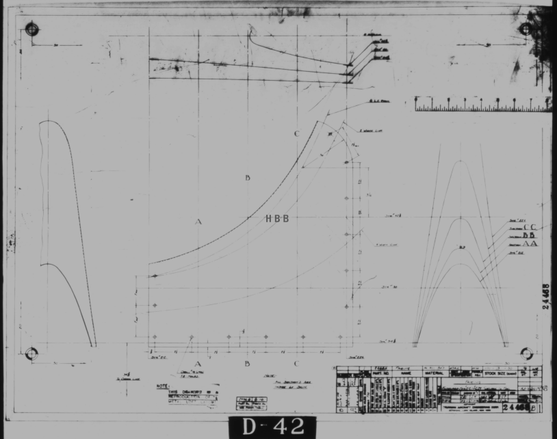
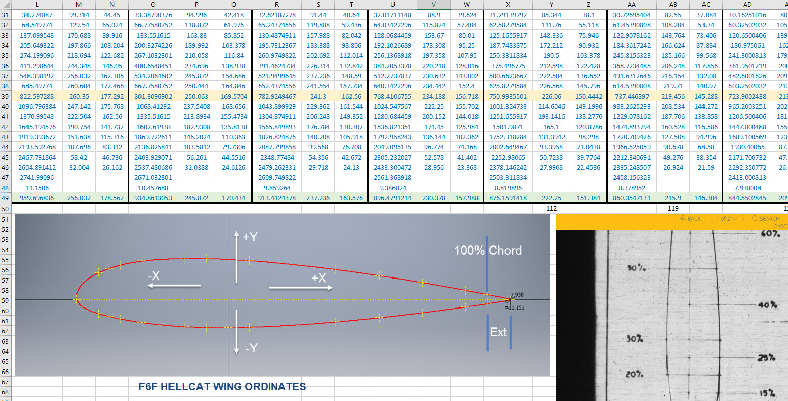
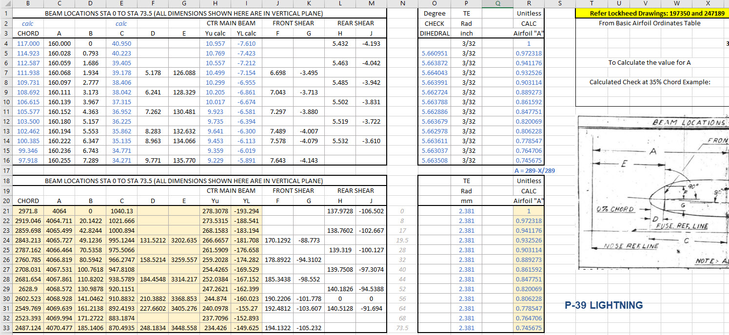
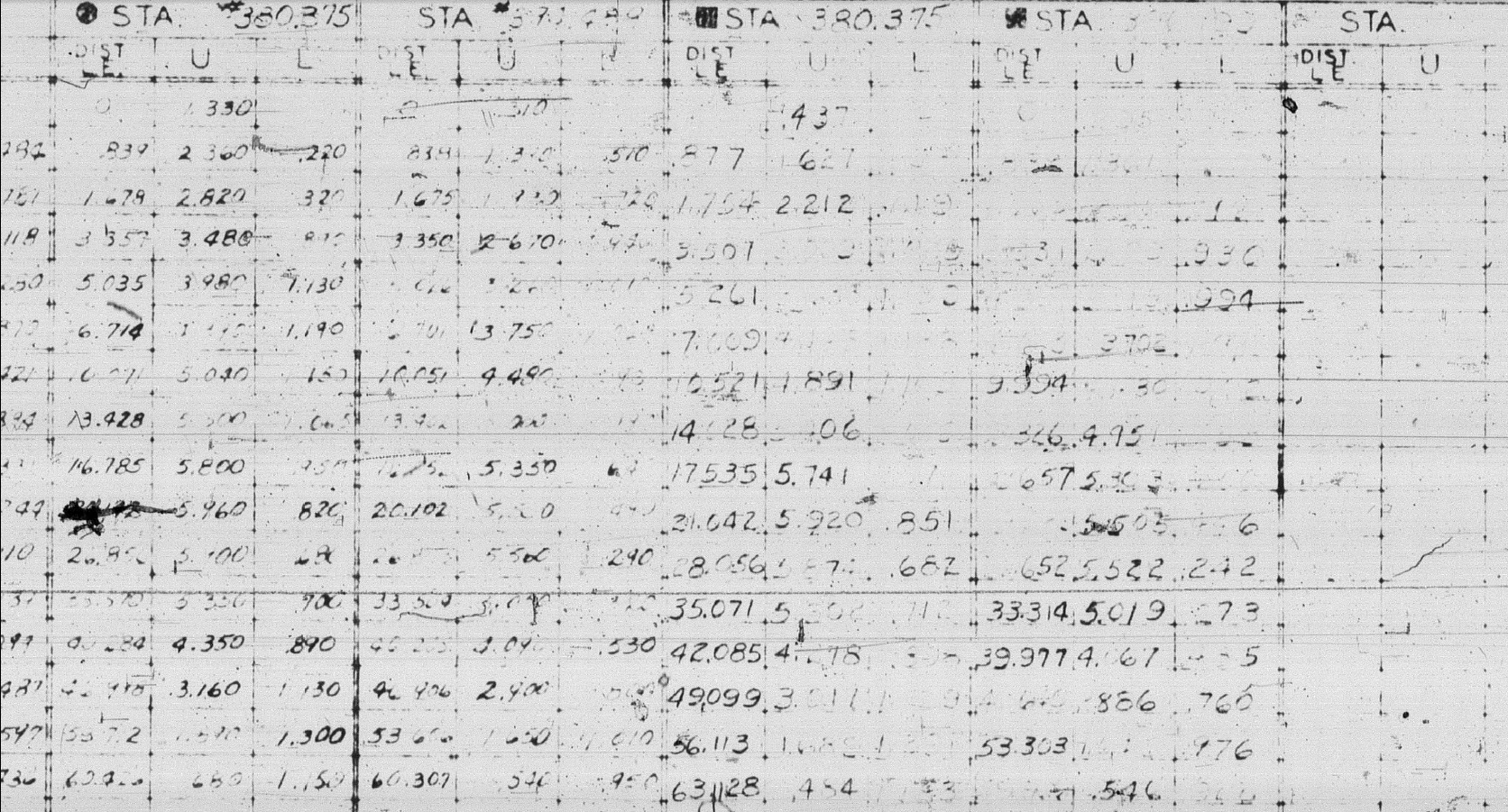
The drawing on the left is the partial profile information for the Fin/Rudder rib and the drawing on the right is the basic profile included on the Ordinate layout drawing I mentioned in the beginning. I surmised that if the Rib drawing follows the same convention as the Ordinate table with logical percentage increments it would be possible to determine the chord lengths of each rib.

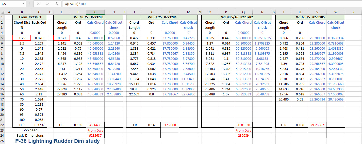
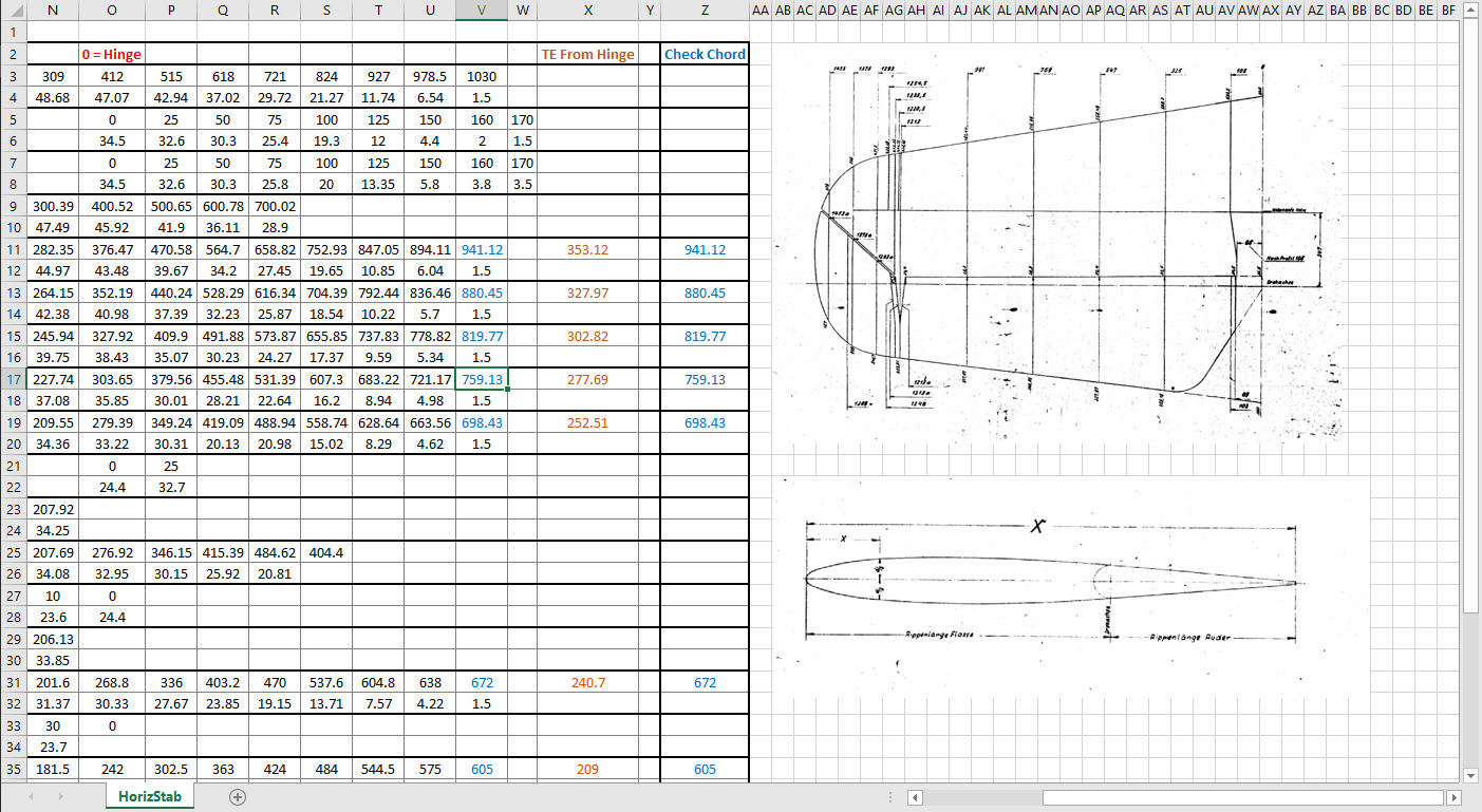
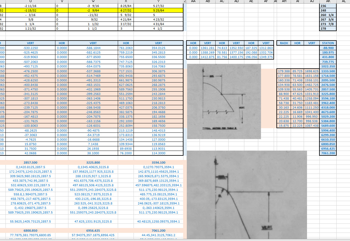
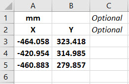
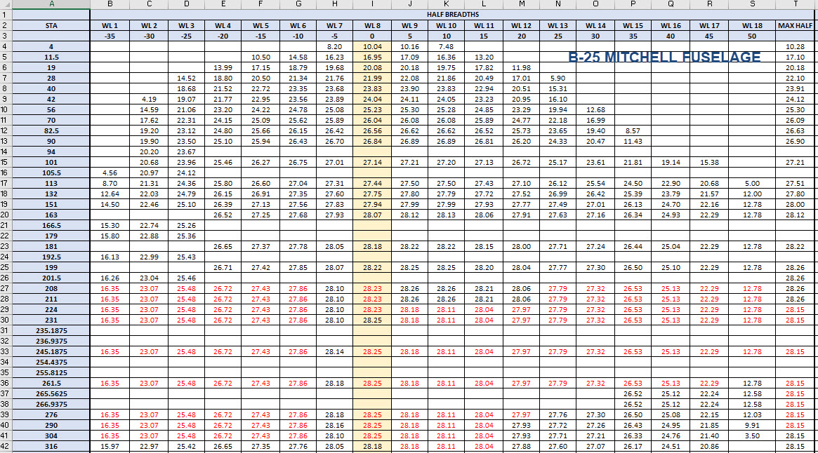
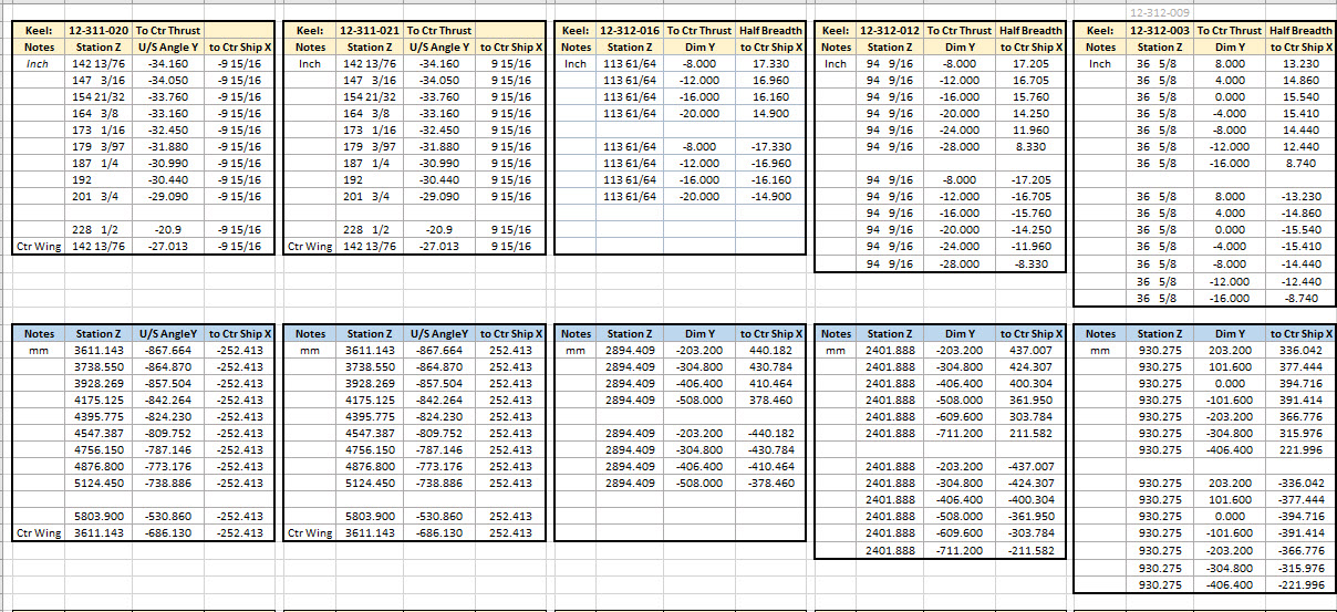
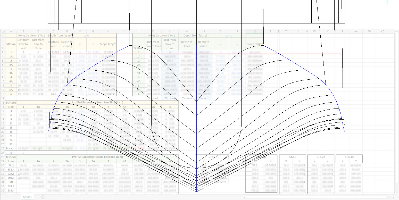
In excel I created this spreadsheet with the Ordinate Table on the left and subsequent tables containing information from the Fin/Rudder Rib drawings. The first 2 columns in each table are the values as noted on the drawings and then to check my theory that they followed a logical sequence I calculated the third column which indeed returned a close approximation of the actual chord length. The fourth column is the new offsets calculated from the derived chord length in each case.

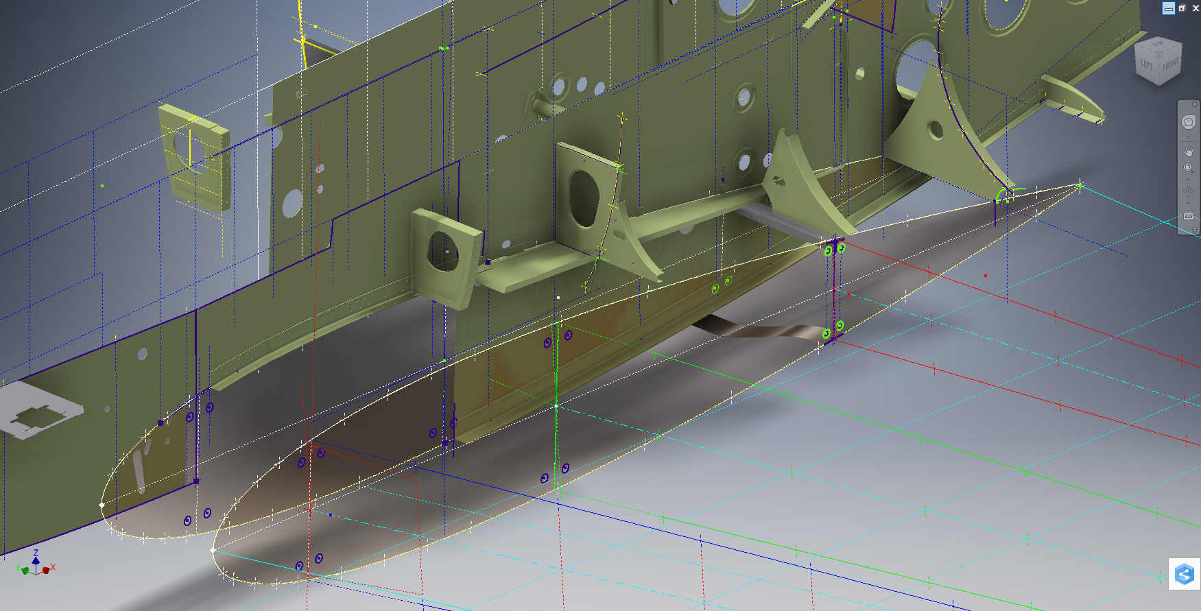
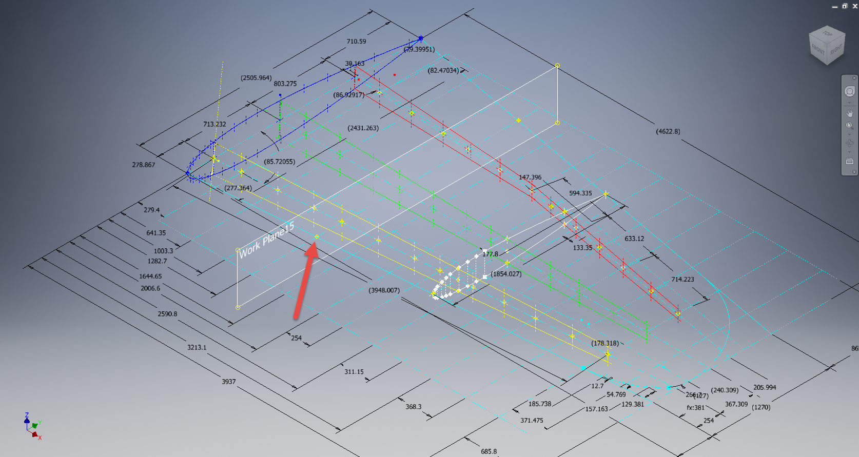
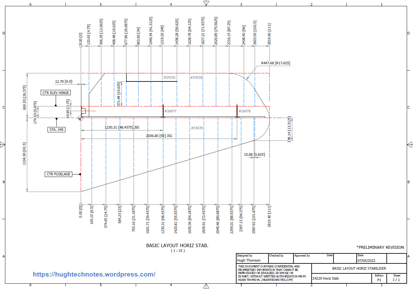
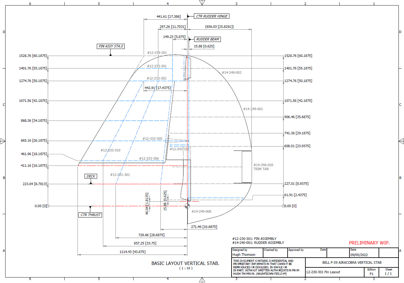
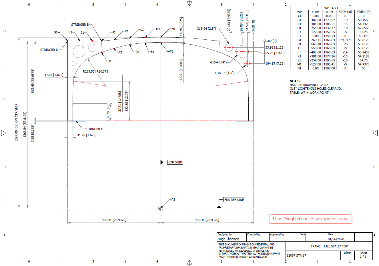
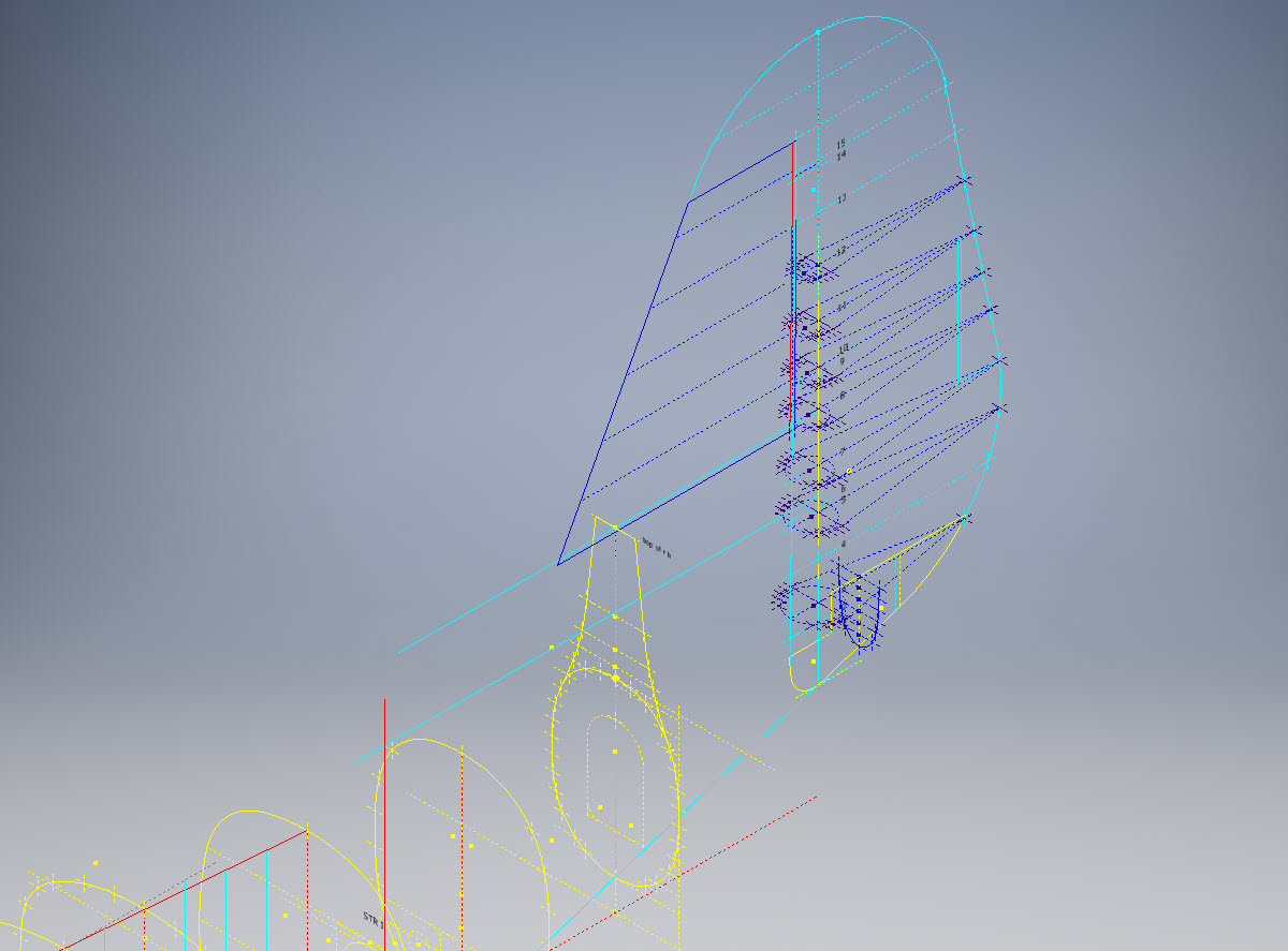
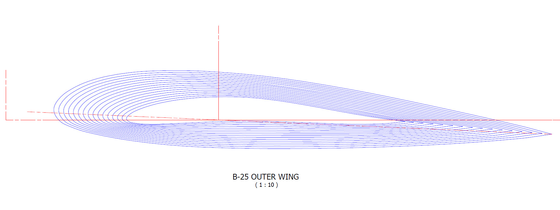
Having established that the rib profile is as I expected it is now possible to create ordinate points to profile the Trailing Edge and define the contours for the Rudder’s ribs. Remember we also have a tab extension to which we have to add an additional fraction of an inch to get the final trimmed profile. As I am calculating and applying the new information to the CAD model sketches I maintain a 2d view to check the overall dimensions to see how they compare.

I am only halfway through the development of the Fin and Rudder layout as shown but will continue the same process to ascertain the remaining curve sections. At the end of the day and similarly the same with the wing the 2d drawing will display 2 lines profiling the Trailing Edge, one which will be the 100% chord ordinate and the other the extended tab. By the way please don’t use any of the dimensions noted on this drawing…it is a study with temporary dimensions!

A lot of work still to do on this which will have to be done for all the spars and ribs to ascertain the correct curvatures of the Trailing Edges. Where occasionally you need to derive specific information it is often beneficial to look at opportunities to interrogate what information you do have to determine the information you need.

Update 26th May 2022:

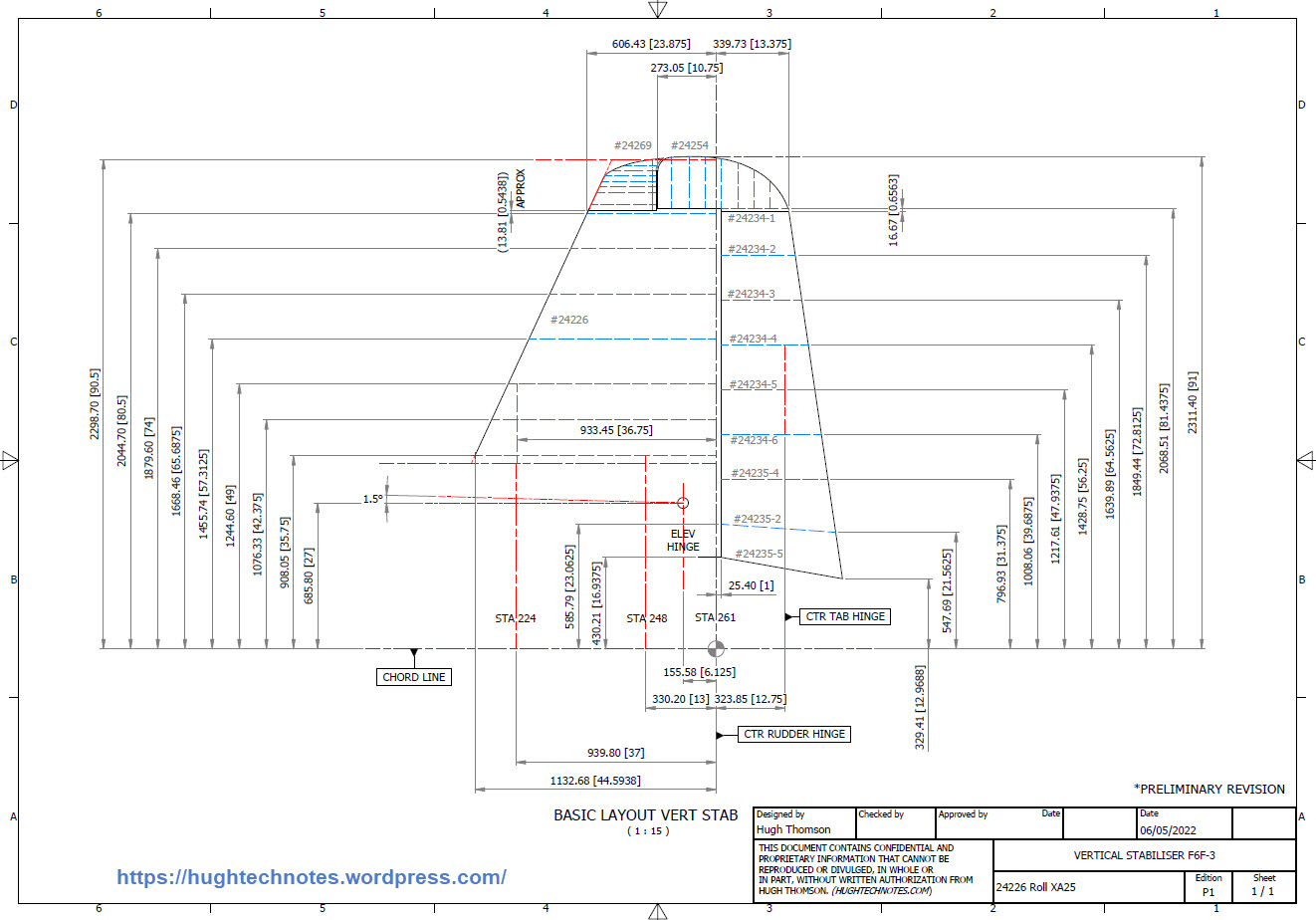
After extensive study and listing of ordinates in stacks of excel tables, I have managed to verify the Vertical Stabiliser dimensions. The Basic or True Rudder line noted on the sheet drawings is defined by the 100% chord dimension for the ribs…this is an important change to the wing trailing edge. Anyway as I need to take a break I thought it may be prudent to provide this update for your perusal. Still some work to do for the top and bottom profiles and of course a general tidy up would be in order…it is still a work in progress!

I could have just accepted the dimensions noted in the Structural repair manual as the end result would have been close. However, it is important where there are slight variations between the manual, the ordinate sketch and the part drawings that every effort is expended to understand the design intent and derive a correct solution.

One further point of interest: the profile for the Vertical Stabilizer is close to being symmetrical about the vertical centre of the full length of the rib chords. I marked out the centres of each rib profile and found only a 3.6mm difference for the top section, however, the variation in the lower section (below WL 21) is considerably more at 19mm… which is too much even accounting for the fractional accuracy from inch measurements.

Update 10th July 2022:

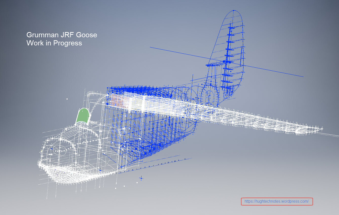
My study of the P-38 Lightning is now finished. I have documented all aspects of the aircraft and compiled an extensive record of dimensions in a comprehensive Excel spreadsheet. The 3d CAD model is supported with dimensioned 2d layout drawings with all models available in native IPT, IAM forms as well as Parasolid XT and 3d DWG.

For more information get in touch, as usual, contact me at hughtechnotes@gmail.com

Technote: Bell P-39 Airacobra Updated Model

Technote: Bell P-39 Airacobra Updated Model

For the last 3 weeks I have been working on an update to the Bell P-39 Airacobra Ordinate and CAD dataset. The original P-39 was intended to be a personal study of the construction and structure and therefore never actually finished. However following a request from a good friend who asked if I could do some work on the Vertical and Horizontal Stabilisers I decided to have a look and see what I could do.

This model is brand new, effectively replacing the old model with a new direction in how these models are presented. The majority of the CAD/Ordinate datasets comprise extensive spreadsheets of dimensional data, drawings and a 3d cad model of the profiles. The idea is that all this data will provide the end-user with a number of options for their own projects. To develop their own models, from either the 3D cad model provided, the 2d drawings or using the spreadsheet data. Fundamental to all this is getting the core dimensions correct which was my primary goal.

I have extended that concept further by applying a base material thickness to the frames and ribs using the Sheet Metal function. For reasons of clarity it is just the basic web profile but what it does is provide the end-user with an actual solid 3d model; dimensionally correct. This can be further utilised for production or used for RC models with the basic frames in place.

This development came about as a consequence of building the Horizontal Stabiliser. This was hampered due to a number of significant Bell drawings that don’t seem to exist as well as a few-dimensional error in the drawings I do have.

Developing this model required a lot of research to achieve the most accurate model possible for the P-39 Stabiliser. For example, the angle noted at “3” is defined on the Bell drawings as 13 degrees but when you check the layout against the Jig mounting points on the fuselage the angle is actually 13.1127 degrees. The material thickness of the ribs was an important factor when calculating this angle.

The dimension at “1” is not on the drawings but I did eventually find this quoted on a NACA Wartime report which aligns perfectly with expectations. The Leading Edge sweep angle is derived after I developed the LE ribs and aligned with known information. This is close and guaranteed to be within plus or minus 0.2 degrees. I have also written to a few companies that have P-39s to see if they are able to verify this angle. Update: Note the leading edge angle has been verified with a new value; see later post on this blog dated 12 July 2022.

The new P-39 Airacobra model and Excel spreadsheets are now online. Dimensionally it covers all aspects, wings, fuselage and empennage. There is also a copy of the old model which is still relevant.

Old Model (more 3d cad bits):

The plan is eventually to revisit the previous CAD Models for the other aircraft projects and add the web material thickness as I have done with the new study. This adds value to the potential use of these models far beyond what I initially intended.

As usual for more information drop me a line at hughtechnotes@gmail.com

Technote: Understanding Ordinate Datasets

Technote: Understanding Ordinate Datasets

I wrote an article on using the Ordinate datasets many moons ago, which is now rather dated so I figured it was time to write an update with a better explanation.

First of all the reason why? It’s like every other construction project where you first start with a skeletal framework and then develop the project’s envelope. Whether it be a building with a steel frame, a boat, even the human body relies on having in place the skeleton on which to build the construction elements.

Aircraft projects are no different and to this end, many manufacturers provide this information in the form of ordinate dimensions. This information occasionally is listed in tables or included on the individual part blueprint drawings. I firmly believe that once you have the basic framework dimensionally accurate then everything else falls into place…so it is incredibly important.

Basic Ordinate Overview:

Let’s take an example from the Bell P-39 Airacobra.

For this aircraft, the ordinate dimensions are noted on the actual part blueprints so I have developed a series of tables listing this information in excel spreadsheets as shown. They list the Station Location from the aircraft Zero plane (this is usually identified by the manufacturer). The Station number is actually the station dimensions from this plane which defines the Z component. The next column on the table is the Vertical Y-component or the dimension to the Waterline and finally, we have the Horizontal X-Dim which lists either the Buttock Line position or Half Breadth dimension.

Commonly the Horizontal axis on the aircraft is known as the Fuselage Reference Line (FRL) or occasionally the Thrust Line. The Vertical Line is simply known as the Centre of the Ship to the Aircraft.

Waterline (WL): Horizontal Axis, Buttock Line (BL): Vertical Axis. An example of this is where we commonly have a designation like WL4…which means the Waterline at 4″ above or below the Centre of the Fuselage. So when it is not specifically dimensioned you would know from the designation where it is located.

Once I have the tables of known dimensions I would occasionally extrapolate this data to list the actual X,Y,Z dimensions in separate tables to make it easier to copy and paste into any CAD system.

As you can see from the above image, the dimensions are initially listed in 3 columns, X,Y,Z and next to that is the same data listed with comma delimiters. The reason for this is because Mechanical design packages like Inventor and Solidworks will recognise separate columns of data in the requisite order as stated whereas Autocad will require combined data for Mulitple Point input as comma-delimited.

The way I do this is to have a separate excel spreadsheet which I keep on my desktop which I call Scrap.xlsx. The format is common as shown in the image on the left though I should note the top 2 rows are optional. If there are no units specified it will default to the CAD template units. I usually don’t bother with the top 2 lines. Once the points are imported into CAD I tend to delete the values in the spreadsheet Scrap.Xlsx and start again.

The comma-delimited column data in the above image can also be copied onto a Notepad Text file and used in Autocad. Worth noting is that if you try to import X, Y, Z coordinates onto a 2D sketch it will only import the first 2 lines and ignore the third…so make sure the columns are in X, Y, and Z-order.

An important consideration is that not everyone uses Inventor or Solidworks or even Autocad which is why the spreadsheets are critical because then everyone can use the data to build their own models.

Actually building the model can be done in several ways. You can build a part file with multiple workplanes on which to sketch the profiles from the input ordinate data or individually in separate part files. You can model the parts in context, i.e. taking into consideration the Station (Z-axis) dimensions so when input into the assembly they locate correctly in 3d space. Or just the X, Y, ordinates in the part file and locate to the Z-axis offset in the assembly.

Dealing with problem data:

This is perhaps one of the main driving initiatives behind the development of Ordinate datasets with regards to the legibility of the original manufacturer’s blueprints.

This example is actually quite reasonable whilst others are quite illegible. As most of these datasets are listed in Inches; which are normally factions; it is easy to confuse whether a fraction is 3/16, 5/16 or 9/16 when all you have is a blob of dark matter.

What I tend to do in these circumstances is develop what I do know and develop the profile using splines to connect the points and then apply the curvature to help determine the missing point location or check that a point is correct.

Occasionally points you need to complete a profile just don’t exist on the blueprints or are completely illegible which will then require more extensive research. Sometimes this information is included in the maintenance or Repair manuals or in the case of the P-51 Mustang a missing point was actually found in correspondence. Either way compiling this data and building the profiles is very time-consuming.

Another fairly common problem is wrong dimensions. Every aircraft project I have worked on from this era has this problem, not because they are bad draughtsman (very much to the contrary) it is because many of the drawings are only records of the Template Lofts and occasionally the dimension is recorded incorrectly. The skill is identifying that the dimension is wrong; it is unwise to assume that because something does not look quite right that it is actually a mistake. So you have to check with associated parts and layouts to be sure.

The image above is the Horizontal Stabiliser leading edge. The rib in blue (1) was obviously wrong because of a distinct kink in the curved edge, which when corrected aligns well with its neighbours. The one in red (2) also appears to be wrong even though the curvature looks fine the forward edge does not match with the projected alignment (I tend to use an Axis feature to check this). Before I apply any corrections I will check the part drawing and then the assemblies to determine if there is an error or if it is actually a design feature.

Locating Sketch Datum Points:

Creating workplanes for sketches as offsets from the primary X, Y or Z planes tends to copy the originating plane datum point which is not always where we need it to be when importing a series of points. The best option is to use the Parallel To Plane Through Point when creating a workplane as this allows you to select the point which will be the datum point on that sketch plane for locating the point data.

I previously wrote an article on this here: https://hughtechnotes.wordpress.com/2017/07/27/technote-inventor-sketch-datum/

Some of the datasets are setout specifically to make it easier to input the data from the spreadsheet. For example, the extrapolated X, Y, and Z, coordinates for the P-51 Mustang wing have been compiled and calculated so they will input at the location of the 25% wing chord. This is assumed to be the logical setout point from the CAD World Coordinate system which saves you a lot of hassle.

If however, you have to create a workplane on an incline this option may not be available in which case you need to adapt the local sketch coordinate system to suit the required datum point.

In Inventor, you would right-click the Sketch in the model browser and select the Edit Coordinate System option which initiates an adjustable Coordinate icon on the sketch.

Suffice to say this icon can be manipulated, moved and rotated to any point on the sketch to suit your requirements. I will do a more comprehensive article on this shortly.

Other Excel Ordinate Examples:

The actual layout of the Ordinate spreadsheets depends entirely on the form from which the data is developed. Where the original blueprint data are listed in tables I will generate the excel spreadsheet in exactly the same format…which helps when checking the data input. If there are no tables but data from the part drawings then I will generate tables according to how the dimensions are noted.

All the dimensions are listed in Inches and Millimetres. I normally extrapolate the X, Y, and Z coordinates to millimetres as this is easier for me to work with…but it is easy to change that to inches if required. All the spreadsheets are fully editable and not restricted in any way.

Finally a quick Excel tip:

If you work with percentages a lot you will find this useful. When entering the value in the cell just add the % sign after the numbers and Excel will automatically format the cell as a percentage value.

Ordinate Data set Availability.

The NAA P-51 Mustang (probably the most comprehensive study) is available as a separate package from the Blueprints archive. The B-25 Mitchell is also a separate package and the Grumman Goose. The F6F and F4F are currently included in the Blueprint archive as they are not so well organised (work in progress) for now.

The Bell P-39 Airacobra is currently included with the blueprints but as I am now working on a new update this will shortly only be available as a separate package.

The P-38 Lightning is brand new and will not be available until June.

Final Note: All the Ordinate packages include the 3D cad model as developed in Inventor. This should not be an obstacle to anyone wanting to interrogate the model as a 30-day evaluation of the Autodesk Inventor is readily available for download. You can even extract sketches from the model as DWG files if required.

Many of the Ordinate packages include fully dimensioned Autocad 2D drawings and PDFs. These are mainly layout drawings and critical location information where it is essential to better understand relationships between wings, fuselage and empennage. Again all these are fully editable.

For all inquiries and feedback please get in touch: hughtechnotes@gmail.com

Updates: F6F Hellcat and P-39 Airacobra

Updates: F6F Hellcat and P-39 Airacobra

While I source new information for the P-38 Lightning I decided to revisit and update the Grumman F6F Hellcat and the Bell P-39 Airacobra Cad/Ordinate datasets. This work relates to the empennage for which I have decided to make the Autocad DWG and a PDF copy of these documents available for download.

These drawings are preliminary Basic Layouts for early release. The 3D CAD model updates will only be available to those that have previously purchased a copy from me directly. Though these won’t be finalised until nearer the end of May 2022. I shall contact the buyers directly in that respect.

Grumman F6F Hellcat PDF &DWG: Download Link

Bell P-39 Airacobra:

I am also in the process of tidying up the Ordinate datasheets to make them easier to read. The datasheets list the ordinates for each frame/station profile in both Inches and Millimetres with a second sheet that extrapolates this data and compiles the data as X, Y, and Z coordinates for input into any CAD system. These X, Y and Z coordinates have initially 3 columns for each ordinate which is ideal for Mechanical systems like Autodesk Inventor plus an additional concatenate column which combines all coordinates comma-delimited for Multiple Point input into Autocad.

Other CAD/Ordinate Datasets:

These CAD/Ordinate packages are designed to help you kickstart your own projects. All the dimensional research has been done for you, which will save you weeks of work.

For more information drop me a line at: hughtechnotes@gmail.com

Grumman JRF Goose: New Project

Grumman JRF Goose: New Project

Just started a new project to determine the structure ordinates for the JRF Goose. Typically for the Grumman drawings, this will require resources from a combination of tabled ordinate data and extrapolated dimensions from the individual part drawings.

With the NAA drawings for the B25 Mitchell I was spoiled as these guys tend to love ordinate tables and it is much easier to develop the data spreadsheets whereas the Grumman guys tend to fragment the information over several drawings. The wing ribs, for example, are actually in 3 separate drawings; the nose, intermediate and tail-end.

JRF_5-at-anchor

Why Ordinate datasets are important;

I spend a lot of time developing these datasets as a record of my research that can be utilised for various purposes including development of CAD 2D and 3D models. As an engineer, I know from experience that when the skeletal framework of an aircraft is correct then everything else will fall into place. I often see modellers dive headfirst into creating 3d part models and end up encountering problems with alignment and fits.

It is therefore prudent to first check the geometry prior to committing to 3d modelling…it will save you a lot of time, frustration and work in the long run.

The datasets already completed for the P-51 Mustang and the B25 Mitchell have been used by restoration companies, researchers, modellers and RC enthusiasts. The criteria for each group vary so it makes sense to provide the correct geometry in formats that can be translated to any engineering systems in a manner that can be used according to their specific needs.

goosehullxc

The Goose Dataset:

The above cross floor drawing is an example where the ordinates are first compiled in a spreadsheet in both inch and millimetre formats. The core data is then extrapolated to determine the workable X, Y, Z coordinates. This is an interesting aspect of the aircraft design as the cross-floor profiles share similarities with the sister aircraft, the J2F Duck. Where I have cross-references between similar aircraft this information will also be included on the spreadsheet as a record of data resources.

goose wing2c

The wings; as mentioned; are compiled from 3 different sections for the nose, intermediate and tail-end which require 3 sets of tables for each rib and then consolidated.

The ribs once integrated into the CAD assembly are then checked at each ordinate point to verify alignment with the neighbouring profiles to ensure accurate alignment. Occasionally the originating data is unclear so it is absolutely essential to continually check neighbouring associations to achieve accuracy.

X2C

The wing tip float: as well as the float profiles; depicted in the image above; I will also be studying the support structure and relationship with the wing.

This ordinate set will comprise the dimensional data as spreadsheets and as 2d DWG cad profiles for every frame and rib. For the main fuselage, the drawings will contain the key dimensional information in lieu of the usual spreadsheets due to the complexity of the frames. All other areas; wings, cross floor, nacelle and empennage will have both spreadsheet data and drawings.

GOOSE STA 17

These datasets are designed to help you get a heads up on your own aviation projects and as a resource for research. I do this work and research so you don’t have to…so please consider supporting my efforts. Thank you.

Update 3rd June 2020:

Have been quite busy figuring out the vagaries of working with the Grumman drawings. They are generally quite good but to be honest the inclusion of a few more ref dimensions would not go amiss! The development of the tail fin and rudder required referencing 3 separate drawings in order to ascertain the correct relationships between the fuselage, tail fin and rudder.

Goose Tail

I also noticed a number of incorrect dimensions during the development of the fuselage and tail. When this happens it is imperative to cross-reference various associated drawings and sometimes even the Structural manual to determine correctness. This is actually where a lot of time is consumed in sorting these issues.

For the wing the ordinates are being checked as the profiles are developed. Part of this process involves developing key structural components as 3d models to ensure that the profile ordinates align correctly. In the following image it shows that the ordinates points align as expected with the red points (intermediate wing section) on the aft of the front beam web and the yellow wing nose points fall on the forward face.

goose wing 1

I am not planning to fully model this aircraft only where necessary to investigate alignments.

TechTip: It can be frustrating working with Grumman drawings…take nothing for granted. The wing ribs as mentioned comprise 3 drawings, the Nose, Box Section and Intermediate. For the sake of complicity I shall refer to them as Nose, Mid and Rear.

W3

One would assume a certain degree of consistency particularly when the detail drawings relate to Station locations. For example: you would expect the STA 37.5 would be a location that would be consistent for the mid and rear sections…but it is not. For the Rear section it refers to the back face of the rear beam and for the Mid section it refers to the front face of the rear beam. So when aligning the various actions it is imperative that the connecting line is either of the chord stations on either side of STA 37.5 (ie STA 40) and not STA 37.5. It is easier for the Nose and Mid Sections as they both have ref dimensions to the common STA 25, however the rear section does not reference chord STA 25.

Seriously a few additional reference dimensions consistently applied would make working with these drawings a lot easier.

I carried out a dimensional study on the spreadsheet data to check the relationships between chord STA, 30, 37.5 and 40. It revealed a number of inconsistencies in the STA dimensions but we did have consistency with the offsets at STA 30 and 37.5 (highlight red).

G8

I would expect that the dimensions from STA 30 and 40 would be consistent with no variation as noted on the Mid and the Rear rib profiles…however that is not always the case. Out of all the ribs only 4 were what I would envisage as being correct. This requires further in-depth analysis to determine the best solution.

This will be a lot of work but a clear example why it is important to record the data in spreadsheets so an analysis like this can be done.

Update 14th June 2020:

Fuselage Frames, Tail Fin and Rudder now complete. Horizontal Stabiliser, Stringers, Flaps and Ailerons, Nacelle and revised wings still to do.

wip

This will be the full package, spreadsheets and drawings. The latter will be all the frames and ribs at 1:1 in Autocad DWG format as well as the full 3d model.

goose keel
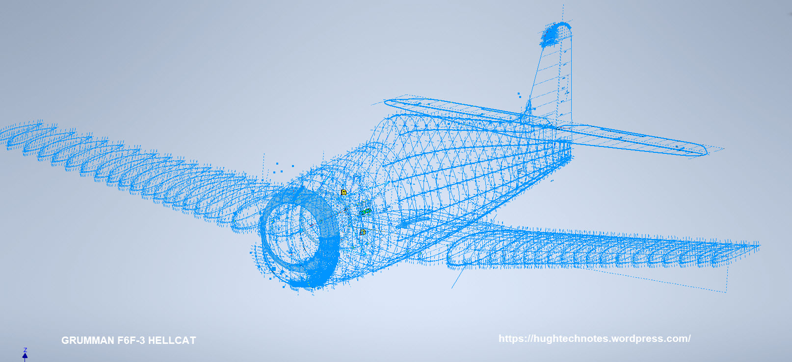
I seriously think this will make a great foundation for an RC model at whatever scale you desire.

Update 2oth June 2020:

With reference to the Techtip above I have revised the wing layout to correct identified anomalies with the Grumman wing rib drawings.

GrGoose1

I first established 5 ribs that are deemed to be correct, setup a work plane at Chord STA 40 and checked the relationship with the established ribs. For reference I initiated 4 axis selected from 4 known points on the ribs. I then placed the Rib at STA 271 to act as a check. The ordinate points on the profile for this rib is within 0.04mm of the projected axis and the dimensional offset from the work plane is only 0.025mm.

Having now established correct alignments I will introduce each of the remaining ribs, then check dimensions for each one with the work plane and each of the 4 axis. The end result will be a dimensionally accurate wing.

NAA B25 Mitchell: New Project

NAA B25 Mitchell: New Project B-25B,C,D

CaptureE

The North American B-25 Mitchell is a medium bomber that was introduced in 1941 and named in honour of Major General William “Billy” Mitchell, a pioneer of U.S. military aviation. Used by many Allied air forces, the B-25 served in every theatre of World War II, and after the war ended, many remained in service, operating across four decades. Produced in numerous variants, nearly 10,000 B-25s were built. These included a few limited models such as the F-10 reconnaissance aircraft, the AT-24 crew trainers, and the United States Marine Corps’ PBJ-1 patrol bomber.

This project will be another research and study effort to develop the ordinate datasets similar to the P-51 Mustang project. The ordinate data is compiled from drawings, reports, manuals, documentation and correspondence so it does take a long time to do.

For example. the above spreadsheets show the work process, starting with recording the ordinates exactly as set out on the NAA drawings. In this case, the original ordinates are in inches so a second table is created to convert this data to millimetres. The third table is the transposed version; retaining original formula cells; which is then used to extrapolate the actual X,Y,Z coordinates for input into a CAD system (the first 10 frames are shown).

B25 STRINGER

This table is the stringer ordinates which follows the same convention of recording the first table exactly as per NAA drawings then converting this to millimetres. The third step is slightly different; transposing the table data in 4 sections to align the data according to stringer number.

B25 Ordinates

This last table is for the wing center section. The process is similar to the previous tables with the main difference being the extrapolated X,Y,Z coordinates originate from the 30% chord. The actual location of intersection between the wing chord line and the wing reference line is calculated at 33%.

B25 WING CHORD

This is a lot of work just to get to this point I have spent in excess of 48 hours and I still have a long way to go. Once the frame X,Y,Z coordinates are listed they are then transferred to individual frames in the CAD system whereby they will be checked for accuracy.

There are a few ordinates that are illegible on the original drawings which will require further intensive research to determine.

To fully complete all the known ordinate spreadsheets for the B25 Mitchell I estimate will consume almost 300 hours of work. The P-51 Mustang set; created in a similar manner; was almost 3 times the number of manhours.

The end result is a comprehensive list of known coordinates that will generate the requisite fuselage, wing and empennage profiles within seconds in all major CAD systems…so it definitely is worth doing.

b25 mitchell ords

Fuselage total X,Y,Z points 2x 1043 = 2086

Wing total X,Y,Z points 2x 870 = 1740

Update 7th May 2020:

Continuing the development of the B25 Ordinate dataset I now have the majority of the wing rib profiles recorded. Some reconstructive work was necessary on the outboard ribs to obviate the poor quality of the original NAA drawings.

Every legible point is added to the spreadsheets and then meticulously created in the CAD system. Where information is unclear the cad extrapolated values are closely checked against the appropriate entry on the original NAA drawing to identify matching numericals or part thereof. Once I have consistency with the graphic output and the NAA drawing information this is then entered into the ordinate spreadsheet.

The attention to detail is typical of my approach to building these ordinate sets. Nothing is taken for granted and the primary reason why these datasets take so long to develop.

b25wing9

b25C Mitchell

Update 12th May 2020: Project Status:

  • Fuselage: Frame Ordinates and CAD Profile 100%
  • Fuselage Stringers: Ordinates and CAD Profile 30%
  • Inner Wing: Ordinates and CAD Profile 100%
  • Outer Wing: Ordnates and CAD Profile 100%
  • Rudder: Ordinates and CAD Profile 100%
  • Vertical Stab: Ordinates and CAD Profile 100%
  • Horiz Stab: Work in Progress.

Update 16th May 2020: Empennage:

Update 19th May 2020: Rear Fuselage:

B25 Rear Fuselage

Often it is necessary to pull together several resource documents into one drawing to better understand key datum relationships as I have done here with the rear fuselage.

Update 21st May 2020: All Done:

This is a good example of what the ordinate datasets are all about.

Making sense of this:

B-25 OUTER WING2

To develop this:

B-25 OUTER WING

The complete list of known ordinate points for the B-25 B,C,D Fuselage, Wings and Empennage are now recorded in a set of excel spreadsheets. A few additional drawings (PDF and DWG) have been created to further clarify the main datum points for aligning the main assemblies and a 3d Autocad drawing of full assembly profiles.

  • Fuselage: Frame Ordinates
  • Fuselage Stringers: Ordinates
  • Inner Wing: Ordinates
  • Outer Wing: Ordinates
  • Rudder: Ordinates
  • Vertical Stab: Ordinates
  • Horiz Stab: Ordinates
  • Nacelle Firewall: Ordinates

All enquiries please contact me at HughTechnotes@gmail.com

P-51 Ordinate & CAD

P-51 Ordinate & CAD Package: 

A comprehensive overview of the Ordinate/CAD package for the P-51 Mustang B,C and D aircraft. This package is the result of over 2 years of extensive research and development incorporating everything I know about the ordinate information pertinent to the P-51 Mustang; now available for download.

Fully Dimensioned Layout Drawings (Autocad 2d):

These are my CAD files that you can use for your own projects. These files are being made available for personal use only and not for commercial gain. Detailed layouts, fully dimensioned.

51j

engine mount revb

Tip 1: The Engine Mount drawing is a good starting point when setting out your CAD model. This will establish the fuselage datum points, Thrust line, Engine mount locations, and Firewall.

The dimensions for this have been triple checked. Incorporates information extrapolated from 6 different documents.

Tip2: Did you know you can work with inch and mm dimensions in the same model. If you happen to be using an mm template and wish to input inch dimensions then just type in the value followed by the unit type; either or in. So for 1 3/8in enter exactly as shown including space and vice versa if working in the inch template and using mm just quote mm units.

Over 228 Autocad 2D Point Profiles Derived from Spreadsheets:

These are my CAD files (DWG) that you can use for your own projects incorporating the point data. These files are being made available for personal use only and not for commercial gain. 2D profiles of all frames for wings and fuselage.Ordinate DWG profile

Ordinate Spreadsheets: 1000’s of Ordinate Point Coordinates (mm and inch):

These are my Excel spreadsheet files that you can use for your own projects. These files are being made available for personal use only and not for commercial gain. All ordinate points painstakingly entered by hand in both mm and inches. Data is sorted and extrapolated to derive 3d coordinates for direct input into most CAD systems.

Original Military Specs AN & MS (fair share) with Dimension Spreadsheets:

Standard specifications and dimensions for parts including turnbuckles, bolts, nuts washers etc. 3D CAD models of these parts are available separately as a collection; refer to the CAD library tab. Relevant parameters are recorded in spreadsheets that can link to CAD models.

2019-10-06_17-03-01The full Ordinate/CAD dataset will literally save you 100’s of hours of tedious work and is available online. For further information please send an email to hughtechnotes@gmail.com 

This Ordinate/CAD dataset is only available from my blog. All work and research were done by me. All spreadsheets and DWG files are fully editable.

Models on CGTrader:

Alongside the ordinate and dimensional research I also have a large number of professionally prepared 3D CAD models for the P-51 Mustang now available for download on CGTrader.These include the Tailwheel assembly for the P-51 Mustang. All parts, including all internal components, nuts, bolts, washers, and pins modeled to original standards. Tailwheel CAD assemblies on CgTrader:

P-51 Mustang TW Shock

exit These CAD models include fully itemized layouts for each assembly.se

As usual please get in touch at the following address for all inquires HughTechnotes@gmail.com 

Messerschmitt: Bf109 Ordinates

Messerschmitt: Bf109 Ordinates:

I recently received an inquiry from a museum regarding ordinate datasets for the Bf109. As I previously mentioned in this earlier post the archive I have has a lot of data that was done by others…so I figured it was quite comprehensively covered.

Anyway, I decided to have a closer look and see what was actually documented and how well it aligned with known data. It turns out to be a bit of a muddle. Although the data is quite well presented I have uncovered a number of inconsistencies and anomalies which I will need to resolve.

8-109.000 G-2 Flugzeug Zuss 2

What I thought would be a quick response to an inquiry has initiated a much more intensive study which admittedly I had not planned for. I will go back to basics with this one, using the existing data as a reference and develop a new set of ordinate data for the Bf109 similar to how I approached the Mustang P-51 project.

I have already started with the Horizontal Stabiliser and part of the way through the Vertical. The tables will essentially be a reconstruction from the Messerschmitt drawings and then compiled to develop the X, Y, Z ordinates for transfer to CAD.

bf109


Technote: Scaling Ordinates

Technote: Scaling Ordinates:

The primary objective of my work is to record an accurate database of ordinate dimensional data for various aircraft fuselage frames, cowls, wings, cockpit, and stabilizers. This database is derived from manufacturers original documents and drawings.

Often the original source documents are poor quality, occasionally almost illegible, but if we have 95% of the ordinates for a frame then it is relatively straightforward using today’s technologies to determining the missing 5%. Where possible I will cross-reference with part drawings or alternative information to verify.

Cowl nose ring3

However, most archive records are incomplete, as was my frustration with the F6F Hellcat. Having completed the wings, fuselage, and cowl I was stumped by the apparent lack of ordinate data for the tail and horizontal stabilizers (even from part drawings).

There are 2 approaches to determining the missing information. The first is to model the information you do know; from part files, supporting documentation and 3rd part resources. This may provide enough information to determine the missing geometry in order to extrapolate a dimensional data set.

The second; and I would never do this myself; is to trace or convert the outlines of the components from the scanned drawings. There are several products available that will convert raster images to vector files but first, we must achieve a properly scaled image to work with. Most raster image from these archives are scans from 35mm microfilm and due to the nature of the process, the resulting image will not be equally scalable in both X and Y directions.

2018-09-14_14-40-13

Assuming you wish to work with CAD and use this image as a background I would recommend the following process to achieve the best result. This particular drawing is created from actual loft templates and includes the locating pins set to a specified distance in each of the corners plus a drawing scale rule.

Some drawings may only have scale rules, either way, the process is the same.

If we insert this image directly into a drawing in Autocad or similar the only option is a user-defined global scale parameter which will scale the image equally in both X and Y directions, which is not what we want. Even once the image is inserted the option is the same.

The best way to circumvent this is to insert the image into a drawing, without any scale parameters applied. Then save this drawing including the image as a DWG file.

Xref this drawing into another drawing and you will be presented with the following dialogue box ( I am using Draftsight but Autocad will be similar).

2018-09-14_15-30-28

As you can see you now have the option to apply different scales to the X and Y directions. This works very well and will provide a very good reference for your work. I should clarify that some CAD products have the option to insert an image as an Xref but the scaling options are not the same as for a DWG file, instead reverts to a global scale option only.

As a workaround for missing information, this is a very accurate way of achieving a good result and will satisfy the majority of applications.

As my projects are records of known dimensional information this process would not be applicable.

Grumman F6F Hellcat: Ordinates:

Grumman F6F Hellcat: Ordinates:

I have come across some interesting information that has provided some clarification of the cowl ordinates. This has enabled me to further the progress of the F6F Hellcat project.

I have also verified the fuselage ordinates which I have subsequently updated. This project is now looking rather good with wings, front nose ring, air scoop, cowl and of course the fuselage ordinates now complete.

F6F-3

As you can see some preliminary work has also been done on the tailfin which will be closely followed by the horizontal stabilizers and eventually the canopy.

It is unlikely that there is sufficient information to fully complete the Tailfin and Horizontal stabilisers ordinate datasets due to the lack of dimensional data for the tail components. At this stage, the best I can do is locate the 2d plans for this area and hopefully return to this project at a later date when more information becomes available. It has been a challenge getting this far with the project.

Hellcat Ordinates/CAD datasets.

Now available online; a comprehensive package comprising detailed spreadsheets (mm and inch) with supporting Grumman ordinate blueprints, Autocad DWG and original Inventor assembly and part files. The entire package covers 90% of the aircraft geometry. See previous posts for detailed discussions on the development.

For all enquiries please email me for details at hughtechnotes@gmail.com.