F4F/FM2 Wildcat Wing Layout Study

F4F/FM2 Wildcat Wing Layout Study

Since my last post, I have further developed the Wing layout which has revealed a number of key considerations that you may be interested in.
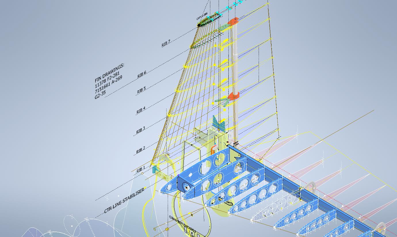
Wing Trailing Edge:

Other than a noted offset on the rib drawings there is no definitive alignment specified for the Wing Trailing Edge. What I found was the Wing Trailing Edge rib profiles were reasonably accurate from which I could determine this alignment.

The component shown in green is the Alcoa K14403 standard Grumman profile for the trailing edge. When I developed each of the wing TE profiles (white) there was a minuscule variation in the alignment, so I needed to determine the best-fit line through those points using Linear Regression Analysis. I could just have easily selected 2 random points from the wing TE profiles which would have been okay but I like to get this stuff right.

By using Linear Regression there is no guesswork or random selection it simply analyses the point coordinates and calculates a line that best fits all these known points. As we have 11 coordinate points to analyze the end result will be an accurate placement of a Trailing Edge line that represents the collection of known coordinate points. The column named Residuals is the offset from the known coordinates to this line. As you can see the max offsets are in the region of 0.3mm…well within normal fabrication tolerances.

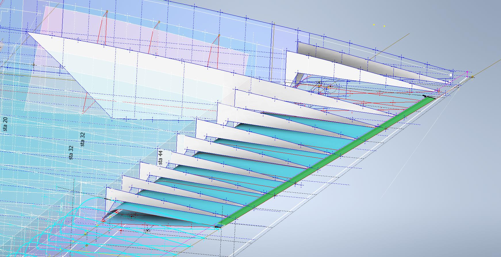
Having now established a correct Trailing Edge I checked this against the flaps (cyan) to see how well the assembly aligns with this newly defined trailing edge. I noted a deviation of 2.2mm on the outboard edge towards the wing tip.

Flaps:

In the image above you can see how the flap assembly does not align exactly with the wing trailing edge. My first impression was that I had made a mistake with the model, so I rebuilt it resulting in the same deviation. So I checked the location of the hinges…they are dimensioned to 4 decimal places of an inch so for all intents and purposes they are exactly located. Further research reveals that there is a return spring on these flaps and I think what is happening is the flap layout is deliberately set out this way so the flap first engages with the wing at the control cylinder end and then the return spring engages closure with the outboard end…hope that makes sense. Grumman has used this type of spring mechanism to engage the closure of wing surfaces elsewhere at the wing folding mechanism.

I believe the geometry for the flaps is correct however my dilemma is whether or not to adjust the alignment to align perfectly for the future purpose of design analysis…and of course should there be any interest in the development of an RC model. One to ponder.
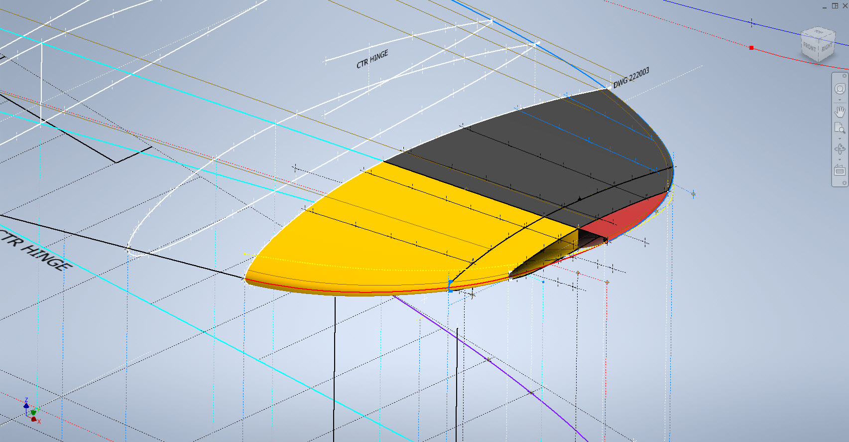
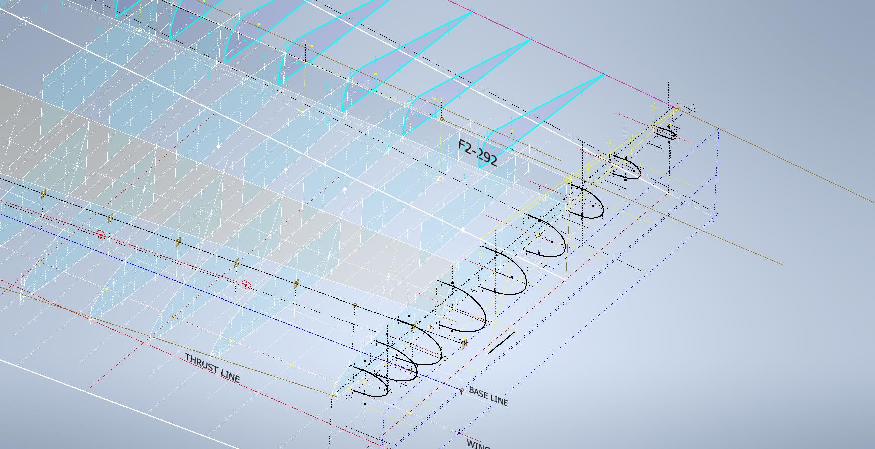
Wing Folding Web:

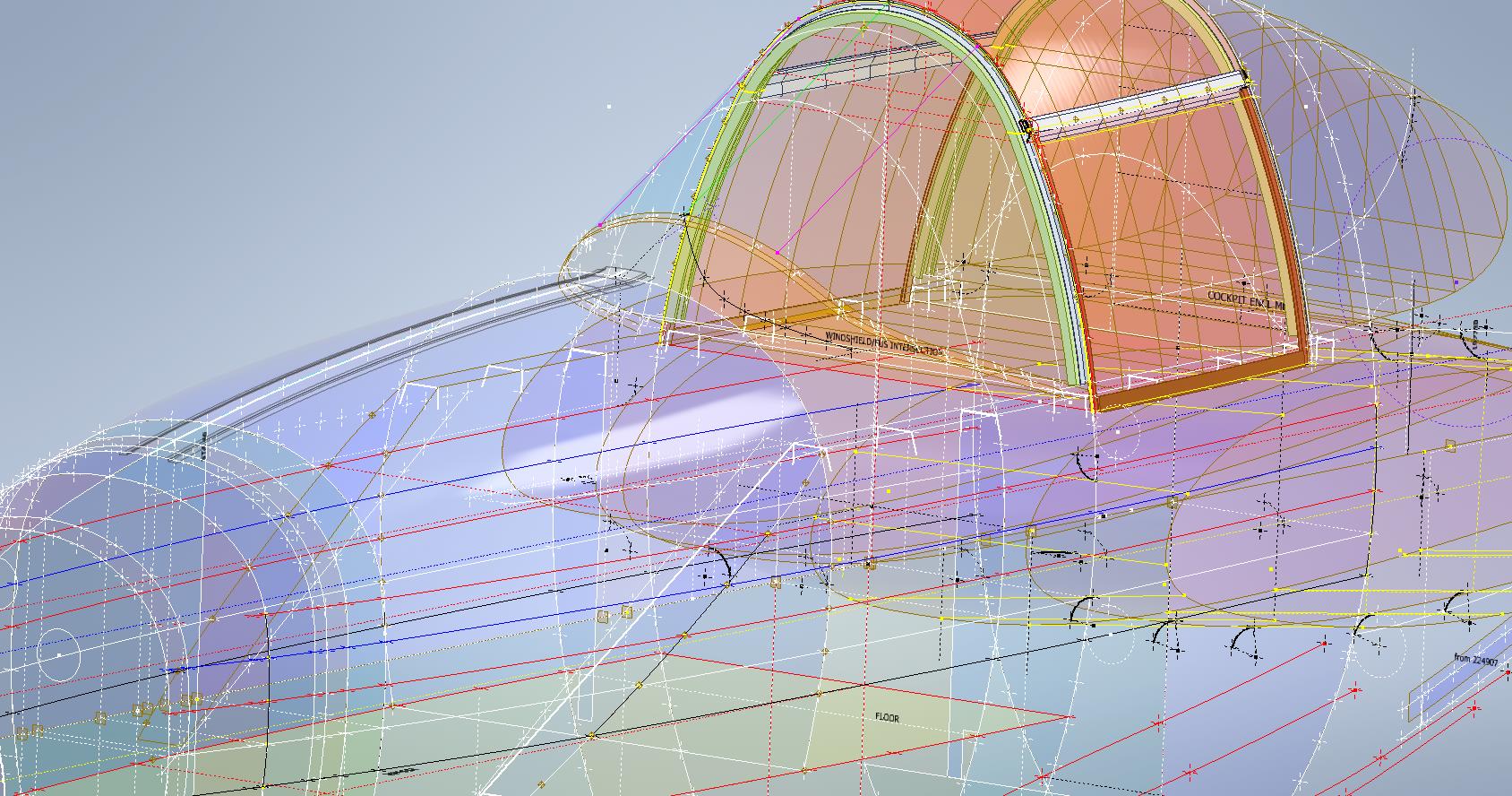
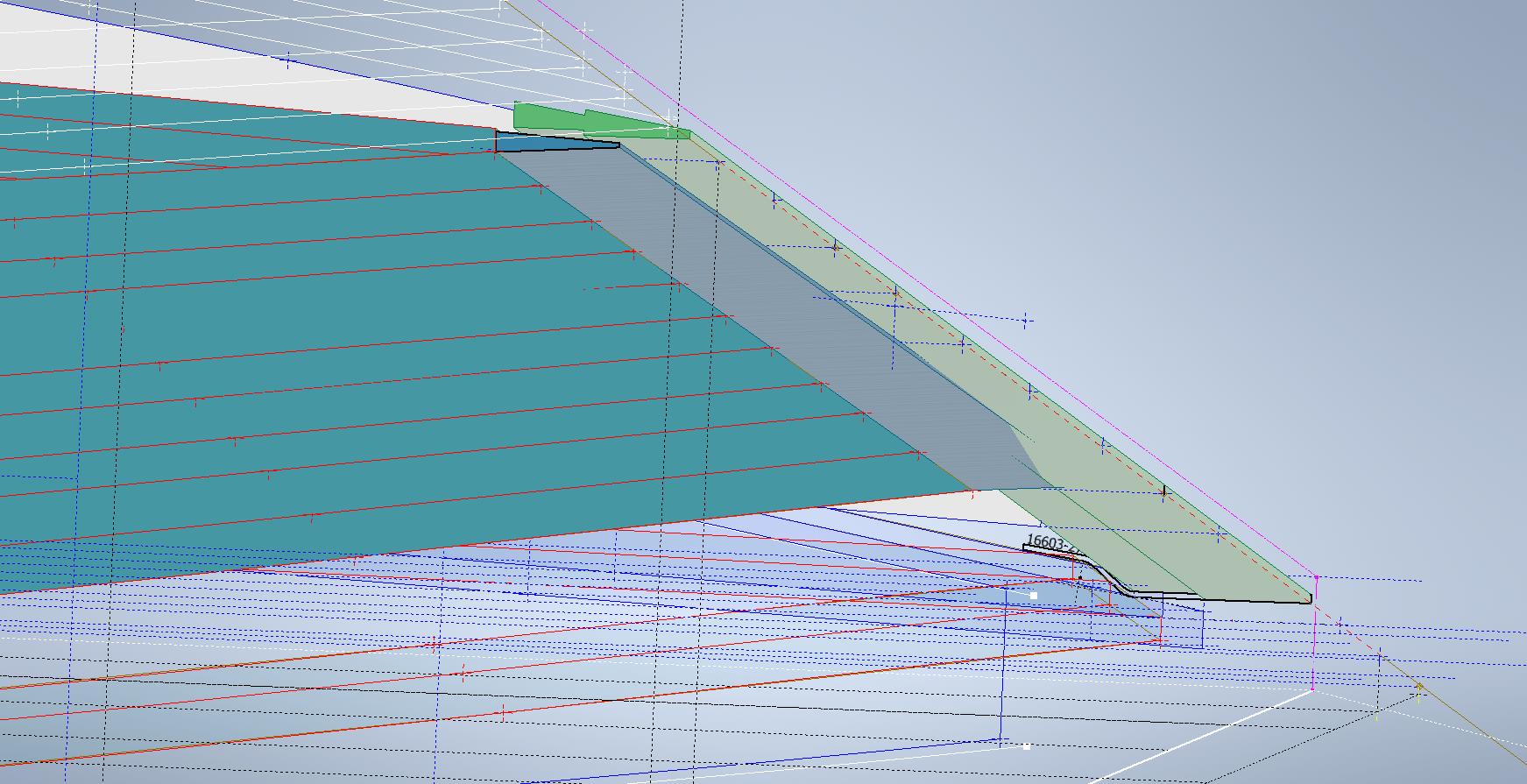
On the inner wing stub section, there is a sloped web plate attached to 3 triangular gussets. This is basically the mating plane for the wing stub and the main wing assemblies at the wing folding joint. This is one area that is not so accurately dimensioned…when you develop the triangular gussets there is a slight variation in the edge slope that this web plate is fitted to and similarly, the profile of the web plate is also marginally out. We are talking about fractions of millimeters but it does matter. I developed this area in a separate assembly where the wing ribs were lofted and then the triangular ribs and web plate were sectioned. Incidentally, the second image above is the only drawing (#7150645) that indicates the slope of this web plate at 50 degrees. You can also see the numerous datum lines that we have for setting out this wing that I mentioned in previous articles.

The mating portion of the outboard wing that engages with this web plate is the spring-loaded assembly I mentioned above…I have yet to do that part…will probably feature in a future article.
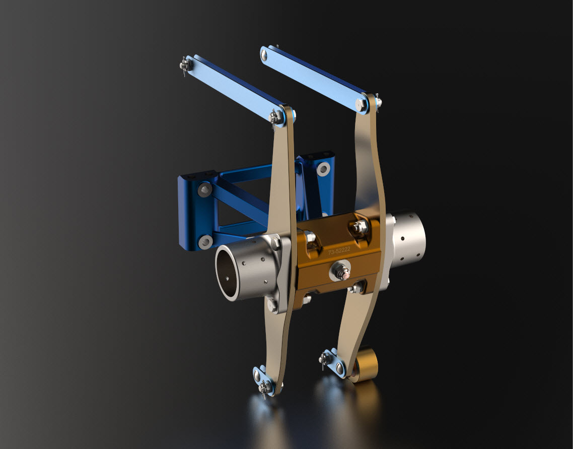
Wing Folding Hinge:

Just a quick update on the Wing Folding Hinge. I have this fully dimensioned now as an ISO View, Front and Side elevations which enables alignment checks with associated ribs and web plates. It is important that the rear face of the main spar aligns with the center of the hinge so these dimensions help establish this correct relationship.

Wing Tip:

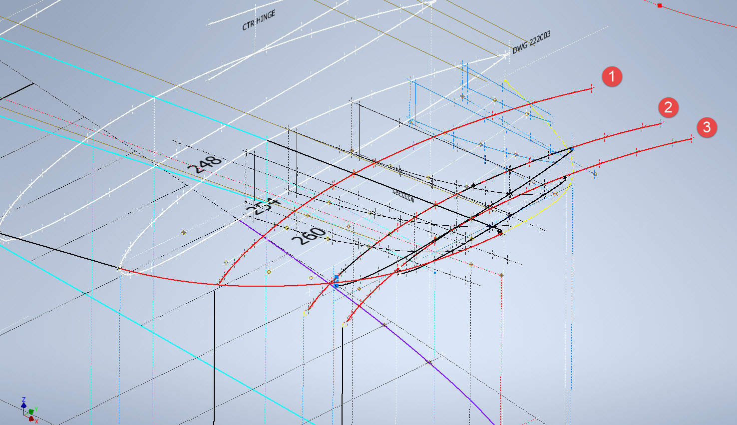
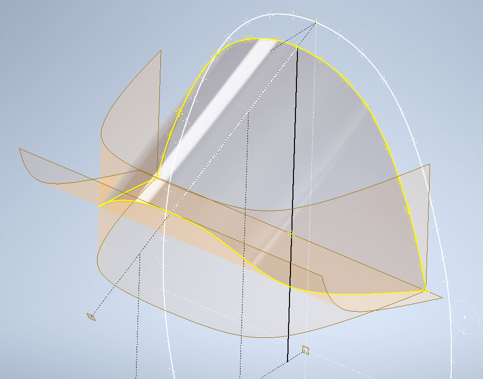
The wing tip sketch profiles are now drawn but there appears to be a slight mismatch with the wing tip rib profile at Sta 222. The Trailing Edge at 55/64″ below the Chord LIne was also puzzling as it did not align with the Trailing Edge line mentioned above. Again my first impression was that I made a mistake with the rib profile…drawn again…same result. I then checked the alignment with the Aileron assembly and whilst the wing rib TE aligns with the Aileron TE the Aileron does not align with the Wing Trailing Edge line.

This one is a bit more difficult to comprehend as there is no logical reason for the Aileron to essentially drop toward the Wing tip…yet the wing tip rib and aileron align well. Again I checked the hinge locations and they are exactly where they should be. I have been in touch with a number of museums and restoration companies to see if they have an explanation and also requested photographs along the edge of the aileron to visually examine the aileron alignment. I will get back to you on this one. By the way, I also carried out a linear regression analysis to determine the exact reference line locations for each aileron rib as a check.

This aircraft is surprisingly complex and whilst there may be perceived anomalies that at first cannot be explained there is usually a good reason for being the way they are. For example, the leading edge of the horizontal stabilizer has a negative camber towards the tip, essentially the leading drops….this is most unusual.

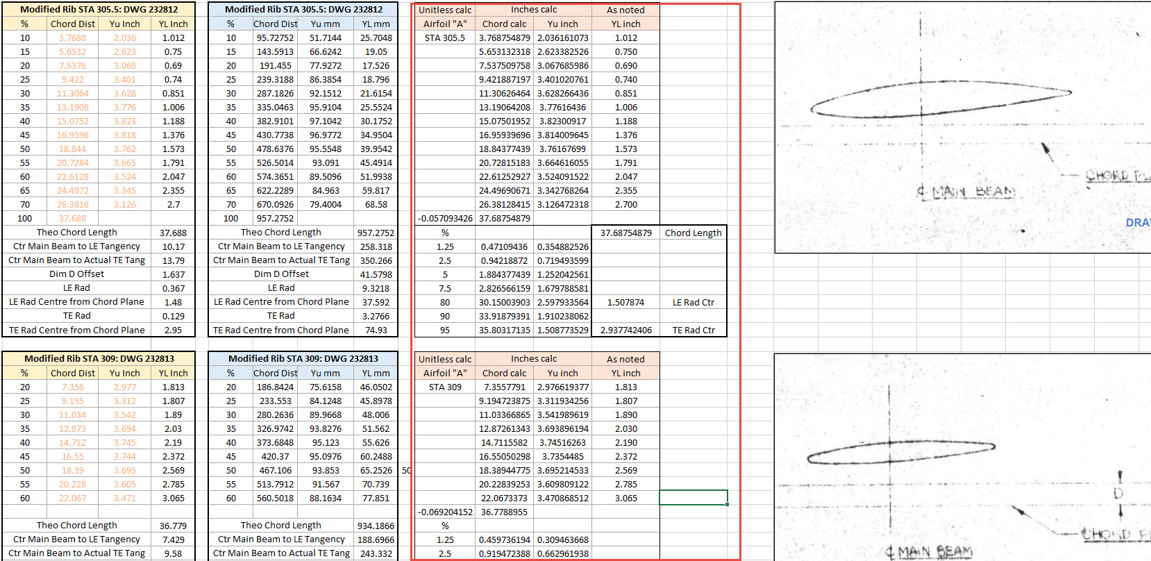
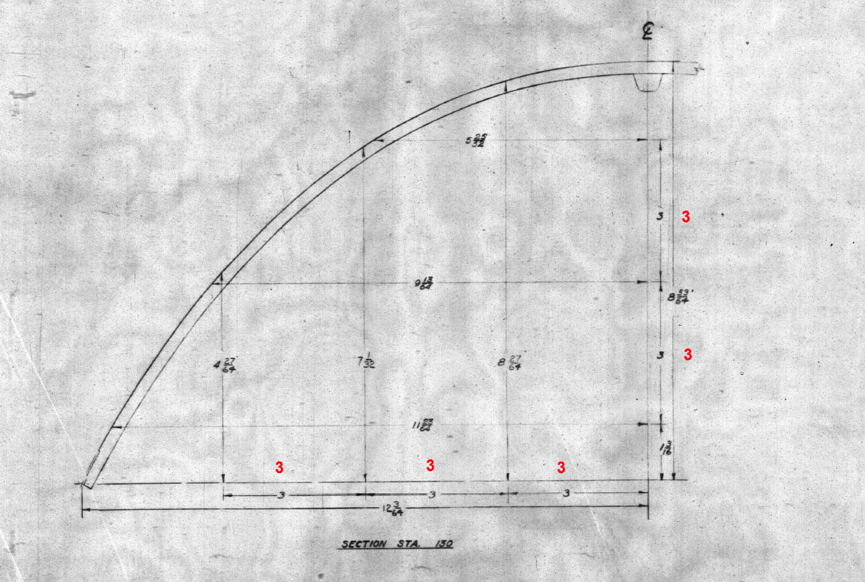
Finally, to make things even more puzzling the wing tip rib profile is not actually a NACA 23009…it is close in profile but it does match exactly…I believe this is a modified NACA 23009. Once I have all the ribs modeled according to the Grumman drawings I will calculate the wing rib ordinates to double-check the profiles…that will be a real pain and time-consuming thing to do as the ordinates are at 4-inch and 2-inch intervals along the chord and not by chord percentage as one would expect…so I need to transpose that data from the cad models to develop the equations for checking.

I have spent an incredible amount of time developing this wing, perhaps more than any other aircraft study I have done. This design is very complex and keeps throwing up small anomalies that at first are difficult to comprehend…it does require a lot of research to figure out the reasons why.

Update 17th Sept 2023:

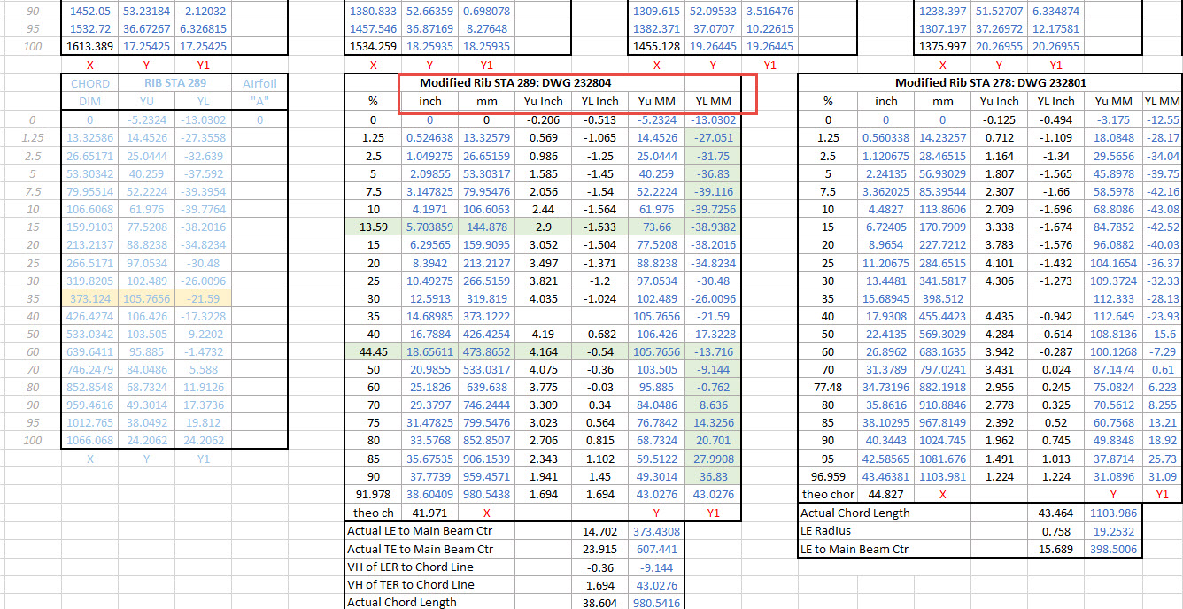
Wing Rib Ordinate Check: As mentioned above I have now carried out a check on the wing rib profile ordinates. Normally I would do this the same way as I calculated the wing rib ordinates for the P-38 Lighting but that is only applicable when you know for certain the root and wing tip rib profiles. The main point of this exercise was to determine the accuracy of the FM2 wing tip profile which is apparently different from the stated NACA 23009 profile.

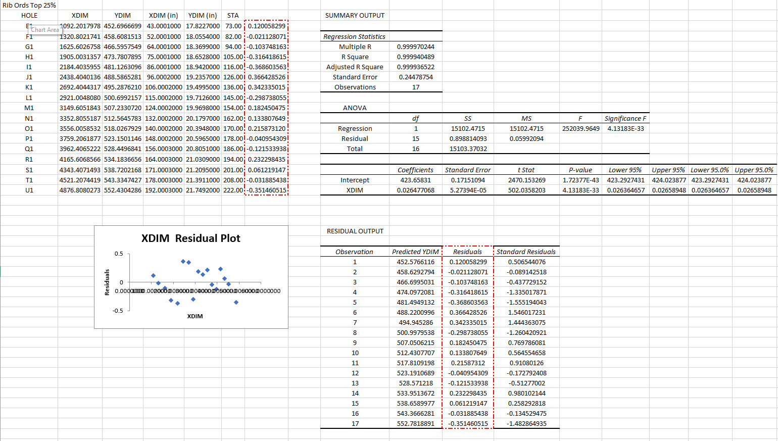
I resolved to do this using Linear Regression Analysis from plotted points on the 15%, 25%, 50%, and 60% chord planes. These percent chord planes actually have to be determined separately because the wing rib ordinates on the Grumman drawings are incrementally spaced at 2″ and 4″ intervals which of course does give us the straight-line projections we need.

Typically I did this for the top and lower ordinates recorded from each rib at each chord plane and compiled the resulting data into a table in Inventor which was then exported to MS Excel for analysis. The analysis confirms that the wing tip profile is accurately drawn and the ordinates on the drawing profile are correct. I shall also do a similar exercise to check the dimensions of the main beam at the flap and ailerons.

Drop me a line for further information at hughtechnotes@gmail.com

Please consider making a small donation, every contribution makes a real difference.

Grumman F4F/FM2 Wildcat Update

Grumman F4F/FM2 Wildcat Update:

Following on from my previous posting regarding the Excel Transpose function; wherein I mentioned the updates to the Grumman F4F/FM2 Cad/ordinate dataset; I thought I would share a few screenshots of progress so far.

As you can see the aircraft is partially 3D modeled…there is actually a good reason for this other than the fact I enjoy the 3D modeling! I have found that on the main assembly layout drawings, the dimensions are often shown to one side of the spar whereas the actual connecting part is defined to the other side. To ensure I get this stuff right I would model the main spar to correct material thickness and check alignments. Admittedly I did get a bit carried away with modelling some of the ribs.

The wing is probably the most complex assembly to do due to the main ribs being in 3 parts…the leading edge, mid-section, and the trailing edge. Each profile will be recorded separately; as per the Grumman drawings and then compiled to provide full rib profiles at each station. The wing also has 5 datum lines that are occasionally misidentified in the part drawings which can be really frustrating alongside incorrectly placed dimensions…generally wrong vertical dimensions are associated with the wrong rib station, more common than I would like.

Still some work to do to finish these main areas as well as the cockpit canopy, fuselage, and front cowl. I haven’t looked at the undercarriage as yet… development of that will be dependent on available information…we will see!

It is not my intention to fully 3D model this aircraft but where it helps check associativity between parts then I will. The project will fully develop all key profiles for ribs and frames which will be fully documented on Excel spreadsheets as a permanent dimensional record. I plan to have this update completed by the end of September.

The aim of these cad/ordinate datasets is to produce the most accurate dimensional records available anywhere for the various aircraft…nothing is assumed or taken for granted.

If you can help me with the spiraling costs of these projects please consider making a small donation. As usual for all enquires please get in touch at hughtechnotes@gmail.com

Technote: 3d Modeling to Clarify Assemblies

Technote: 3d Modeling to Clarify Assemblies

Interspersed throughout this blog are many examples of Technotes describing techniques and problem-solving primarily for 3d CAD modeling. Many of the part examples shown are actually created to address another major issue with Assemblies.

It is not uncommon for the assembly drawings to be either unclear or simply void of key information that would help establish relationships between sub-assemblies or parts. In many examples, it is simply that the reproduction of the microfilm prints is not sufficiently clear to comprehend what is going on, otherwise the omission of basic dimensional relationships.

For the P-51 Mustang, I fully developed the rear Landing Gear mechanisms to clarify what the heck was going on as the NAA Assembly drawings details were obscured.

It is too often the case that general assembly drawings tend to be nothing more than an illustrated parts list with few key dimensions that define locations or relationships between the individual parts. This is also true for many of the sub-assemblies. For the P-51 Tailwheel sub-assemblies, I also developed 2D detail drawings showing key dimensions and parts lists. Ideally, I would have developed presentation drawings showing the exploded views of each of these assemblies to provide further clarification…perhaps a project for the future.

In the case of the P-38 Lightning, I have developed the Landing Gear assemblies to check the ordinate dimensions… which by the way are good. I now have the Coolant Radiator assembly which was again developed to check ordinate data but also for the same reasons as I did the models for the P-51 Tailwheel.

Typically the general assembly pictorially shows the sub-assemblies without any key dimensional information to define the location or part relationships and similarly, the sub-assembly for the clamp is not that much better. This is important stuff as occasionally they are the only reference material we have to help define ordinate data that is missing from the archive blueprints.

The Coolant Radiator is compromised by wrong dimensions as well…the top clamp cover, for example, had dimensions for the connection to the rod with the part drawing showing conflicting locations for different views of the same part.

The problem here is the connecting bracket item 224045 cannot possibly be 1″ from the edge of the cover plate whilst the overall dimension of 6 7/16″ prevails. I initially had located that bracket at 1 inch which seemed to be correct at the time because it fitted the part profile but when I introduced this into the assembly drawing it would not correctly align with the radiator. However, when I revised this using the 6 7/16 inch dimension it worked. That connecting part also caused more problems because the face of the part is machined 1/64″ which is not taken into account when positioning the part in the assembly.

Accumulatively this resulted in the overall width of the clamp assembly being smaller than it should be. This only came to light when I modeled the 234183 almost inconspicuous part as the stated dimension of 9.25″ did not fit with my initial layout..my first thought was this may just be an oversight but when I tried to align the main support frame (in gray) it did not align correctly. I went through everything and realized that the machined face of the corner parts connecting to the rod as shown may not have been taken into account and when removed the alignment was better and the 9.25-inch dimension on the strap was now correct. I am convinced that there should be spacers/washers between those connecting parts but this is not apparent on the assembly drawings. There remains a small discrepancy of 0.8mm which I am unable to account for….as this mainly relates to a clamp mechanism that will be compressed on assembly it was probably not deemed important but when you are trying to establish baseline dimensions it is actually very important.

The Part catalogs generally are your first port of call when developing these assemblies but they do not contain the key dimensions you need so these 3d CAD models are essential to achieve clarity. Incidentally, while we are talking about part catalogs it is important to understand what parts belong to which version of the aircraft. For the P-38 Lightning, the first few pages list the version and serial numbers which in turn are listed elsewhere where a Usage code is assigned. In this case the “e” is essentially the P-38H and the “bv” is the P-38J. The P-38 Part catalogs tend to show the version variations on one page; which can be really daunting; whereas others may show the version differences on separate pages…so you have to be attentive.

As I mentioned at the beginning of this article the main purpose of these assembly models is to achieve clarity and to check dimensional relationships. I think this is very important stuff that would certainly benefit from exploded views in conjunction with clear assembly 2d drawings.

As usual, get in touch if you can help support my work. hughtechnotes@gmail.com

P-38 Lightning: Ord/Dimensions Study Complete

P-38 Lightning: Ord/Dimensions Study Complete:

The P-38 Lightning Ordinate/Dimension study is now finished after 7 long months. Initially, I had planned on doing this study in 3 months; working night and day; but alas due to the complexity of this aircraft this drifted into 7 months.

All areas of the aircraft have been studied, and modeled with all known, and henceforth many previously unknown dimensions collected and recorded in a comprehensive spreadsheet.

All bulkhead and rib profiles are generated for the wings, ailerons, elevators, horizontal and vertical stabilizers, rudder, fore and aft booms, fuselage, cockpit, and flaps. The latter was a challenge as the Lockheed drawings were unclear about the relationship of the flaps to the wings…however, after some research, I was able to resolve this issue to determine the exact positions of the Wing and Center Section flaps. The flap details are fully dimensioned now on 2d Acad drawings…that was the last hurdle.

Further to the Ordinate study I also have full 3d Cad models for the Nose and main Landing Gear Assemblies.

For further details get in touch: hughtechnotes@gmail.com

P-38 Lightning: Fuselage Update

P-38 Lightning: Fuselage Update

The P-38 Fuselage development has been a real challenge. When I first started this project it seemed to me that the fuselage was well documented with stacks of ordinate information and therefore should be a fairly straightforward model. The front section and the Cockpit enclosure are actually quite well documented but the Aft section and the mid-fuselage section; forward of the cockpit; most definitely are not. After more than 6 weeks this part of the project is still very much a work in progress.

The Cockpit enclosure: There are glass profiles for the cockpit enclosure but they are from the XP-38 early model; which on inspection; in comparison to the little-known information for the later production models suggest they are very close but do vary by 1.2mm but only on the side profiles. I suspect the glass was thickened slightly when they started production. I have to work with what I have and in the absence of sufficient information on the production models’ glass dimensions I have opted for a compromise. As only the side dimensions change with the top profile and interface with the fuselage remaining the same I think working with these profiles in conjunction with the structural elements of the production P-38s will work out quite well.

Ref 3rd image: In the 3rd image I have highlighted the location of the profiles at Station 123, 126, and 154. Sta 126 and Sta 154 are absolutely critical in setting out the cockpit enclosure and yet they are not documented nor do we have the drawings listing those dimensions. However, we do have the dimensions at Sta 123. On the windshield drawings, there is a note that states the profile at Sta 126 is the typical profile for the windshield moving forward…logically you would think therefore Sta 126 will match the profile at Sta123. I checked this and it is close but because we also have the glass profile at Sta 126.093 any minuscule deviation will have a profound impact on the curvature when eventually this is lofted. To be sure of maintaining good curvature continuity I lofted all the center section glass profiles and extended the edges by 12mm and then trimmed this resulting profile at Sta 126 and Sta 154. This gave a good result and to check I then swept the Sta 126 profile along the line of the Windshield center line and examined the profile with the known profiles at Sat 123 and of course at the interface with the fuselage. The variance was something close to 0.03mm…that is good enough for me which now ensures good curvature continuity throughout.

Aft Section; As mentioned we don’t have very much ordinate information for the Aft Fuselage Section which will require extensive research of all parts drawings from which we can extrapolate individual points that hopefully will be sufficient to fill in the blanks. The image on the left is a good example where I have drawn the various profiles for the fillet tangent to the fuselage and the wing.

Most of the drawings for the Fillets include the Tangent Points for the Fuselage and the Wings which I included in the model that now collectively gives us a reference line for the side of the Aft Fuselage at the top and bottom of the wing. Each fillet curve was checked against the ordinate surface for the wing and adjusted accordingly taking into account the skin thickness; these were also checked against known bulkhead profiles in this area.

The second image; on the right; shows how we can also use the main longitudinal members in a similar fashion to help ascertain key dimensional information to assist with the development of the aft sections. The red lines are the longitudinal members where the part drawings contain relative dimensions to the Fuselage reference line and the Centre of the Ship. Again each of the dimensions was checked against known bulkhead profiles where the average variation was in the order of 0.012mm. It may seem too small a variance to be of any consequence but when I later have a need to use these lines when creating the surfaces they have to be exact…so in each case the point was adjusted to be an exact intersection with the bulkheads. Inventor is very fussy when lofting with a guideline with no room for error…so this has to be exact.

Ultimately the goal is to find as many part drawings as possible with dimensional information that I can use to eventually have enough data to build the relevant missing Aft Section profiles. Typically this will be the main longitudinals, the skin parts, and of course the fillet drawings. This is painstakingly slow work as virtually every part drawing in this area is being reviewed for potential data that will help me achieve this goal and there are a lot of drawings!

Similarly, the process will be the same for the fuselage area forward of the cockpit which again sadly lacks a lot of key profiles. The research is where the time is expended in developing these ordinate sets…so far for the fuselage alone, I have spent in excess of 6 weeks of continuous work to get to his point, and still a lot to do.

Finally, both the P-39 and the P-38 ordinate dataset models are updated with a new approach to how these datasets are being built. I still have the extensive Excel spreadsheets listing all known dimensions but for the model, each ordinate profile is now inclusive of a surface patch. What this means is that conversions of the model for use in other cad systems will now provide a surface plane as well as a sketch profile which helps the model builder very quickly create the bulkheads for these scale models.

The P-38 is almost complete with the Boom, Wings, Horizontal and Vertical stabilizers, Flaps, and Ailerons all modeled and recorded. The Landing gear is almost fully 3d modeled as well…which is great for those that are keen on super detailing their RC models. These models have also proven to be enormously useful for the Restoration groups one of which I already work with on a P-39 Airacobra restoration.

Update 14th June 2023:

I have been developing the key Aft center profiles at the top and lower part of the fuselage. This is actually quite exciting stuff as there are not a lot of pertinent ordinate dimensions for the Aft Fuselage so I resorted to building profiles from individual part drawings.

For each part sketch profile, I have extrapolated various curves to determine the center work points. What is exciting about this is the eventual lower fuselage curve (in magenta) is absolutely perfect…normally when you derive work points from half a dozen different parts in inches there is an expectation that the eventual curve would show the odd deviation…but it didn’t. The curvature analysis shows this to be absolutely spot on.

Update 23rd June 2023:

Fuselage Aft Assembly: Almost finished with the ordinate study for the fuselage Aft assembly. This work involved generating cross-section profiles from stringers, longitudinals, bulkheads and fillets to derive series of points from which to build the curved profiles. Each profile built is checked against the existing ones by lofting a new surface profile, then a sketch cross section generated to check the curvature maintains alignment with the existing profiles. This is done for every newly generated profile. Ultimately I will end up with the best-fit surface for the Aft Fuselage Assembly. All new points will be recorded in the Main Spreadsheet and fully dimensioned on individual drawings.

Technote: P-38 Lightning Wing Tip

Technote: P-38 Lightning Wing Tip Development:

Developing this wing tip turned out to be more complex than I originally thought it would be. Because the model required a few interesting techniques I figured it is worthy of a quick technote that hopefully will assist others.

First, off the bat, you will probably have noticed the center partition which came about as a consequence of the development process. I will try to explain how this transpired…read on for more details.

What we have is essentially one main rib profile at Station 289 and 2 others towards the tip which you would normally just loft to achieve the finished surface assuming that the required outline guide rails were included in the initial data set. Actually in this case we didn’t have those curved outlines as a 3d profile only a 2d outline on the plan view. Even with the guide rails in place just lofting the full rib profiles did not work due to the continuity of the rails in a circular manner that prevented a successful loft.

By the way, the circular guide rails at “A” and “B” were generated as intersection curves using a side profile (top right in the background) and the plan profile to derive the resulting intersection lines. I initially wanted to extrude the 2d plan profile and build a 3d curve on the face of the surface but I was unable to apply a tangent constraint to align with the Leading and Trailing edges…so my only option was a 3d intersection curve.

Realizing that a full rib profile loft was not achievable I decided to fill each rib profile with a patch surface and then split the surface at the main beam intersection, which incidentally is perpendicular to the ribs. So this gave me a patchwork of surfaces fore and aft that I used as surface profiles and lofted each section as shown using the guide rails at “A” and “B” and the center rail at “C”…this created the partition I mentioned in the beginning.

Once the main fore and aft sections were modeled I then proceeded with the extreme tip which was simply a case of again adding a surface patch to the small projecting profile in the center and lofting the surfaces separately as before. Occasionally when you have problems with lofting it often helps to break it down into more manageable chunks.

Accuracy is extremely important to ensure a good surface finish with no small deviations or folds. So I checked the coordinates of each profile mathematically and adjusted the dimensions accordingly for the top surface.

The rib profile at 1,2 and 3 was adjusted to the new coordinates for the top line only but making sure that the LE and TE were tangential to the mathematically generated curves shown in red. These end ribs are actually modified profiles according to the tabulated information on the Lockheed drawings…apparently, the profile at the wing tips is based on a NACA 4412 airfoil but when I generated a 4412 it did not match…I am not sure why but it is something that warrants further research. As I did not have the mathematical formulas or guidance on hand to check the lower profiles I accepted what information was contained in the tables…mind you I could have generated a line equation from this information in Excel. Incidentally, all the wing ribs were checked mathematically with the resulting dimensions used to generate the profiles throughout.

The first image shows a sample of the modified values at Rib station 289, highlighted in green alongside the normal profile on the left. The second image shows the explanation of how the main wing rib profiles were generated. All this information is included in the CAD/ordinate dataset. Also on the second image, you can see a typical rib profile extracted from the Lockheed drawings which shows the 0% chord is actually set back from the Leading Edge, which is most unusual. This created a few problems because now I had to determine from the CAD model the Actual Leading Edge before I could define the curved guide rails for generating the wing tip lofts.

This all may seem overkill and a lot more work than one would expect just to build a wing tip but the Inventor Loft command requires absolute precision when lofting with guide rails so it pays dividends to mathematically check everything where possible to ensure successful lofting. I shall update the CAD/Ordinate dataset over the next few days to include this new data.

.

.

.

Technote: P-39 Airacobra Update Horiz Stab.

Technote: P-39 Airacobra Update Horiz Stab.

In a previous post, I covered the significant new model for P-39 Airacobra. This model is fully inclusive of all aspects of the aircraft. Within this post, I mentioned the extensive study involved in determining the layout for the Horizontal Stabiliser; the dimensions of which were unclear in the available blueprints

https://hughtechnotes.wordpress.com/2022/05/18/technote-bell-p-39-airacobra-updated-model/

I was particularly keen to establish verification for the leading edge angle and though I had written to a number of organisations that have the P-39; surprisingly none of them took the time to either acknowledge or indeed reply…which of course was disappointing. From my experience, the industry is normally very supportive with regard to technical inquiries.

I revisited the documentation I do have and established that relevant information was included in the NACA Wartime Report L-602 which gives the chord length at Sta 49.25. It turns out; from my initial assessment; that the dimension at “2” was barely 2mm out and the Leading Edge angle is now 16.7796 degrees.

I mentioned in my last post that this latest study is available now which also includes the original model; which was more of a 3D modelling exercise than a dimensional study.

The P-39 Airacobra new CAD/Ordinate study is an impressive project.

All inquiries as usual to; hughtechnotes@gmail.com

Technote: Divide a Line in Inventor

Technote: Divide a Line in Inventor:

Dividing a sketch line in Autocad is very straightforward and the question is often asked how this can be done in Inventor. There are a number of options to do this which I will explore and then I will discuss an application where the solution is not so obvious.

Where you have a known length and you wish to locate a point at 20% of the LENGTH it is simply a matter of applying the formula “LENGTH*0.2” for the dimension value. Another option is when you want to divide the line into 5 equal portions then you can use the RECTANGLE Pattern command. You first set the number of points, expand the dialogue and select FITTED; you will then need to select the line dimensions or measure as I have done here for the value.

Another way of doing this is to draw five line segments in succession and apply an equal constraint to each one. For the above; the length is a required parameter, so what do you do when you don’t actually know the length?

The following example is the P-38 Lightning Horizontal Stabiliser tip for which I wanted to document the ordinate points for the ribs. The ribs perpendicular to the stabiliser axis are known dimensions based on the standard profile however I also needed to record the profile dimensions of the ribs set at an angle to the main axis. Admittedly the Lockheed archive does contain a number of ordinate profiles for the canted ribs where unfortunately the majority of dimensions are illegible.

I like to record numbers so it should come as no surprise to those that visit this blog regularly that I was keen to tabulate the ordinate profiles for these canted ribs. The above image shows a number of magenta profiles which are the rib templates illustrating how the surface converges towards the tip extents. Incidentally, the diagonal lines on the main rib profile actually have a purpose…as you view the stab tip on the elevation you will notice that the ordinate points (projected) align with those diagonals.

Getting back to the main subject. The wing rib and horizontal stabiliser ribs follow industry-standard percentage increments for defining the ordinates as shown in the following image. Now we are getting to the main topic…where I wanted to transfer the ordinate locations for the perpendicular ribs to define the ordinate profiles for the canted ribs.

The Horizontal stabiliser ribs are based on the NACA 0010 airfoil profile which is listed as per the Lockheed drawings in the table on the left. The column on the immediate right is the calculated values to improve accuracy which also verifies the recorded data. The table on the right is the transposed calculated values for the main perpendicular Horizontal stabiliser rib with a chord length of 45″.

The above image is the plan view for the Stabiliser tip which shows the centres for the canted ribs and over to the right a number of red vertical dotted lines indicating the position of the reference perpendicular rib profiles. Between those ribs is a blue dotted line with a small circle indicator which is actually the main subject of this article.

The easiest way of defining the canted ribs is simply to loft the known perpendicular profiles and cut along the axis of the canted ribs…it definitely is the quickest way of doing this. However, that leaves a lot of miscellaneous activities in the cad model which just adds clutter.

Transposing the location of percentage increments from the rib table ordinate table to the canted ribs is done like this.

The perpendicular profile chord is the blue dotted line and the canted rib is the red centre line. The LENGTH is the chord length and the dimension A is the percentage increment on that line that we need to find the comparative intersection for on the cant rib. At this point, we do not know the LENGTH as this is dependent on the line position relative to the cant rib at whatever percentage increment we chose.

As mentioned at the start of this article for say a 20% chord dimension we could simply draw 5 lines in succession and apply an equal constraint and so on for the equal divisible portions…but that is not very practical.

So what we do is to locate the template rib line at any arbitrary point on the cant rib and then dimension the length…it does not matter at this stage what the dimension is. Now, this is the key thing we must do…select the LENGTH dimension and change it to a Driven Dimension. Now define the percentage increment (multiplied by Length) you wish to interrogate from the NACA table above and the template rib line will automatically relocate to a position where the Dim A is actually the percentage dimension you define of the total chord length. The software calculates the correct length according to the parameters specified.

An example would be where you specify 15%: you would write “0.15*D20” where D20 is the Driven Dimension.

I have included in the ordinate spreadsheets a table that will calculate the ordinate rib offsets depending on the chord length derived from the above exercise.

You then simply transfer those ordinate offsets to the intersection point of the cant rib. It really is quite clever when you think about it…you are asking the software to define the length of a line based on a percentage value relative to another canted line within boundaries specified by the arc.

Of course, I did not have to do this for all the cant rib offsets just the ones that were missing from the Lockheed drawings.

The P38 Lightning project is now finished. Only known dimensional data is included in this study. The engine Nacelle and Carb intake are omitted due to lack of dimensional information…however the creative among you will find it straightforward to interpolate fairly accurate profiles from the known information incorporated in this model and accompanying spreadsheet dataset.

Drop me a line at hughtechnotes@gmail.com

Technote: Inventor Sketch Blocks

Technote: Inventor Sketch Blocks

I have uploaded a video showing the mechanism for the Main Landing Gear for the Lockheed P-38 Lightning. This was created using the Inventor Sketch block feature which is a great tool to understand how these mechanisms work and provides an opportunity to examine the operational relationships.

Landing Gear mechanisms are quite complex and at first glance at the drawings, it can be difficult to fathom how they actually work. One way of visualising this mechanism and understanding the extent of the operation is to use Sketch Blocks.

The way this works is that you first build your sketch; minimise constraints, and select the elements that form each of the components; whether that be hydraulic cylinders, linkages, axles etc. Then you would constrain them according to how the mechanism should work…in this example, the cylinder actuator rod is constrained to align with the centre of the cylinder and virtually everything else is concentric constraints at each of the nodes. There are a number of good Youtube videos that show how this is done.

The dimension shown is a “driven” dimension which will change according to the location of the operation. You could of course have driven dimensions for the angles to check the max and minimum inclination. The quality of the video is not great but you get the idea.

Video link: P-38 Main Landing Gear Operation

For better precision, it is always best to use the Simulation environment with relative constraints applied accordingly to confirm operational parameters but for a quick check on movement, the Sketch Block feature is a good solution prior to committing to modelling.

Update 16th June 2022 LG Hinges:

Have you ever wondered what the Main Landing Gear Door Hinges look like?…

Technote: P-38 Lightning Cockpit Canopy

Technote: P-38 Lightning Cockpit Canopy

These are the basic profiles for the P-38 Cockpit Canopy glass panels derived from the XP-38 drawings. Knowing that there were differences between the prototype XP-38 and the production models I was initially reluctant to accept the XP-38 dimensions for developing the cockpit canopy. The production drawings do not contain any useful information to develop these profiles nor indeed was there any drawing stating the inclination angle of the windshield. There was also not enough information from the Lockheed ordinate drawings for the fuselage frames which left me with the only option to use the XP-38 information.

It transpires the dimensions on the XP-38 drawings are indeed pertinent to the production models. There are exceptions which relate to the side windows.

The drawing on the left is the P-38H side glass frame and you can see this is dimensioned as a radius value which differs from the XP-38, which is defined by ordinate dimensions. There is also a slight variation in the overall length, so I naturally presumed that there may be other variables that conflicted with the prototype model. The only way to know for sure was to build the model based on the XP-38 and cross-check against known information with the production models.

So after 3 days of frustrating intensive work, I now have the base model for the XP-38 glass profiles and I have concluded that the profiles for the front, top and rear panels dimensionally are compatible with production variants. The only area that has marginally changed is the side panels, although changing from ordinate to radial dimensions still retains alignment with the known fuselage frames.

Also worth noting is that Lockheed uses a 3-inch grid system for aligning all the fuselage components which are useful when you are trying to locate these panels where no location is noted…you just have to align the 3-inch offsets to the grid. Each of the 3-inch offsets on this drawing section for example can be matched with the full-size grid to locate the correct elevation for the top glass panel and so on.

It is actually a really clever idea and helps obviate any doubt about where an item should be located.

One further tip when working with these Lockheed drawings is that for plan views and elevation views there may not be enough dimensions to fully locate a 3d point for determining a complex curved line.

For the windshield, there was sufficient information in the vertical plane and the horizontal plane but as they were not related I could not derive specific 3d points from this data alone.

So I resolved to replicate this on 2 sketches and extrude a surface profile for each sketch. The intersection of the surfaces gave me the requisite 3d glass mold line.

The final check; that ensures this is correct; is to view the final glass panel along its axis to check that the curvature matches exactly with the top of the ordinate fuselage profile at STA 126…which it does.

For some reason, the ordinate dimensions are on STA 123 instead of STA 126 which means the end result will need to be projected to get the full glass panel model…I haven’t done that here. These are primarily dimensional studies and I tend to only include 3d models where this benefits the purpose of confirming data integrity. Oh by the way the inclination angle for the windshield is 27 degrees…don’t be sidetracked by the frame connectors that show 26.5 degrees…the reason for the 0.5-degree variance relates to the interface with the rubber sealing. Hopefully, you will find this useful.