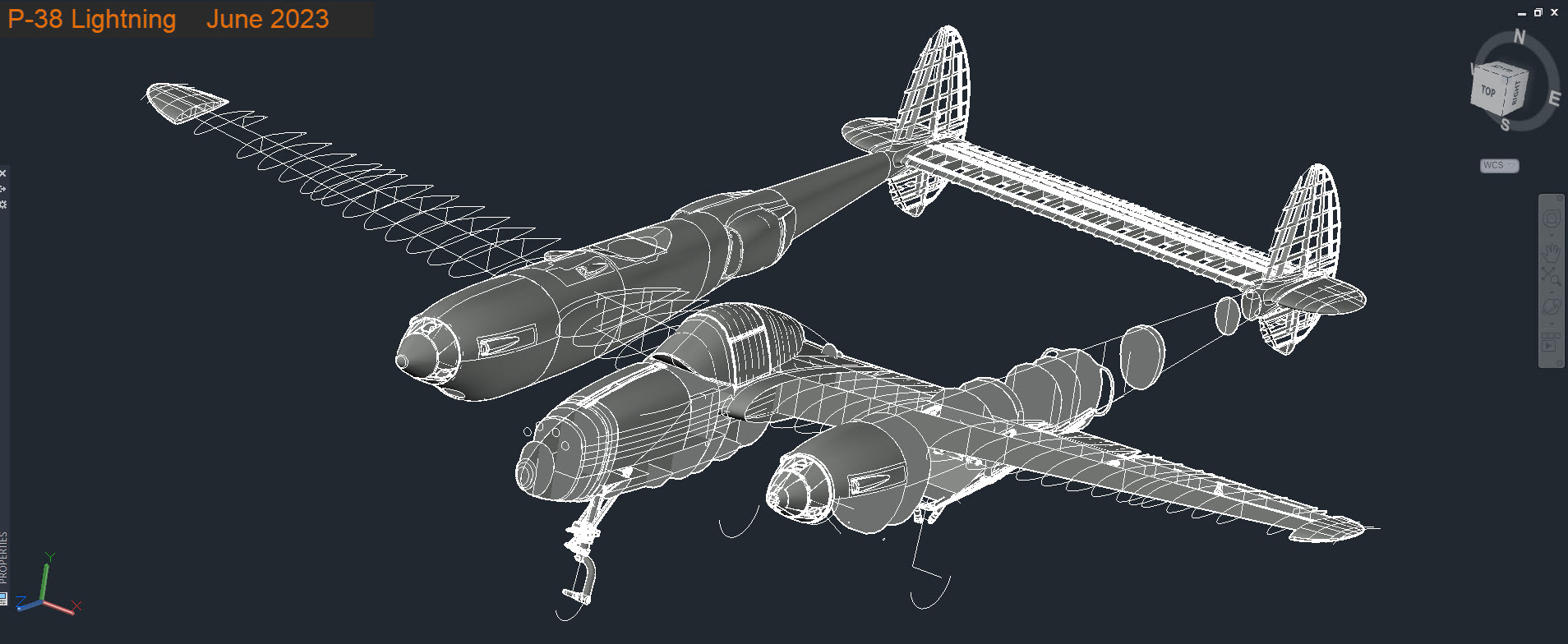
P-38 Lightning: Fuselage Update
The P-38 Fuselage development has been a real challenge. When I first started this project it seemed to me that the fuselage was well documented with stacks of ordinate information and therefore should be a fairly straightforward model. The front section and the Cockpit enclosure are actually quite well documented but the Aft section and the mid-fuselage section; forward of the cockpit; most definitely are not. After more than 6 weeks this part of the project is still very much a work in progress.


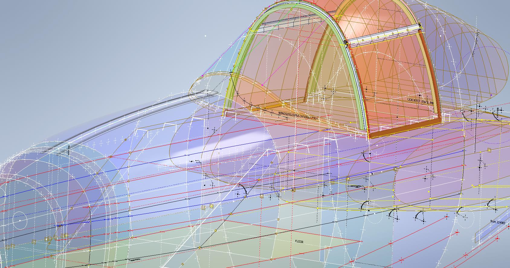
The Cockpit enclosure: There are glass profiles for the cockpit enclosure but they are from the XP-38 early model; which on inspection; in comparison to the little-known information for the later production models suggest they are very close but do vary by 1.2mm but only on the side profiles. I suspect the glass was thickened slightly when they started production. I have to work with what I have and in the absence of sufficient information on the production models’ glass dimensions I have opted for a compromise. As only the side dimensions change with the top profile and interface with the fuselage remaining the same I think working with these profiles in conjunction with the structural elements of the production P-38s will work out quite well.
Ref 3rd image: In the 3rd image I have highlighted the location of the profiles at Station 123, 126, and 154. Sta 126 and Sta 154 are absolutely critical in setting out the cockpit enclosure and yet they are not documented nor do we have the drawings listing those dimensions. However, we do have the dimensions at Sta 123. On the windshield drawings, there is a note that states the profile at Sta 126 is the typical profile for the windshield moving forward…logically you would think therefore Sta 126 will match the profile at Sta123. I checked this and it is close but because we also have the glass profile at Sta 126.093 any minuscule deviation will have a profound impact on the curvature when eventually this is lofted. To be sure of maintaining good curvature continuity I lofted all the center section glass profiles and extended the edges by 12mm and then trimmed this resulting profile at Sta 126 and Sta 154. This gave a good result and to check I then swept the Sta 126 profile along the line of the Windshield center line and examined the profile with the known profiles at Sat 123 and of course at the interface with the fuselage. The variance was something close to 0.03mm…that is good enough for me which now ensures good curvature continuity throughout.


Aft Section; As mentioned we don’t have very much ordinate information for the Aft Fuselage Section which will require extensive research of all parts drawings from which we can extrapolate individual points that hopefully will be sufficient to fill in the blanks. The image on the left is a good example where I have drawn the various profiles for the fillet tangent to the fuselage and the wing.

Most of the drawings for the Fillets include the Tangent Points for the Fuselage and the Wings which I included in the model that now collectively gives us a reference line for the side of the Aft Fuselage at the top and bottom of the wing. Each fillet curve was checked against the ordinate surface for the wing and adjusted accordingly taking into account the skin thickness; these were also checked against known bulkhead profiles in this area.
The second image; on the right; shows how we can also use the main longitudinal members in a similar fashion to help ascertain key dimensional information to assist with the development of the aft sections. The red lines are the longitudinal members where the part drawings contain relative dimensions to the Fuselage reference line and the Centre of the Ship. Again each of the dimensions was checked against known bulkhead profiles where the average variation was in the order of 0.012mm. It may seem too small a variance to be of any consequence but when I later have a need to use these lines when creating the surfaces they have to be exact…so in each case the point was adjusted to be an exact intersection with the bulkheads. Inventor is very fussy when lofting with a guideline with no room for error…so this has to be exact.
Ultimately the goal is to find as many part drawings as possible with dimensional information that I can use to eventually have enough data to build the relevant missing Aft Section profiles. Typically this will be the main longitudinals, the skin parts, and of course the fillet drawings. This is painstakingly slow work as virtually every part drawing in this area is being reviewed for potential data that will help me achieve this goal and there are a lot of drawings!
Similarly, the process will be the same for the fuselage area forward of the cockpit which again sadly lacks a lot of key profiles. The research is where the time is expended in developing these ordinate sets…so far for the fuselage alone, I have spent in excess of 6 weeks of continuous work to get to his point, and still a lot to do.
Finally, both the P-39 and the P-38 ordinate dataset models are updated with a new approach to how these datasets are being built. I still have the extensive Excel spreadsheets listing all known dimensions but for the model, each ordinate profile is now inclusive of a surface patch. What this means is that conversions of the model for use in other cad systems will now provide a surface plane as well as a sketch profile which helps the model builder very quickly create the bulkheads for these scale models.
The P-38 is almost complete with the Boom, Wings, Horizontal and Vertical stabilizers, Flaps, and Ailerons all modeled and recorded. The Landing gear is almost fully 3d modeled as well…which is great for those that are keen on super detailing their RC models. These models have also proven to be enormously useful for the Restoration groups one of which I already work with on a P-39 Airacobra restoration.

Update 14th June 2023:
I have been developing the key Aft center profiles at the top and lower part of the fuselage. This is actually quite exciting stuff as there are not a lot of pertinent ordinate dimensions for the Aft Fuselage so I resorted to building profiles from individual part drawings.


For each part sketch profile, I have extrapolated various curves to determine the center work points. What is exciting about this is the eventual lower fuselage curve (in magenta) is absolutely perfect…normally when you derive work points from half a dozen different parts in inches there is an expectation that the eventual curve would show the odd deviation…but it didn’t. The curvature analysis shows this to be absolutely spot on.
Update 23rd June 2023:
Fuselage Aft Assembly: Almost finished with the ordinate study for the fuselage Aft assembly. This work involved generating cross-section profiles from stringers, longitudinals, bulkheads and fillets to derive series of points from which to build the curved profiles. Each profile built is checked against the existing ones by lofting a new surface profile, then a sketch cross section generated to check the curvature maintains alignment with the existing profiles. This is done for every newly generated profile. Ultimately I will end up with the best-fit surface for the Aft Fuselage Assembly. All new points will be recorded in the Main Spreadsheet and fully dimensioned on individual drawings.


