Restoration Insights: The Risks of Working from Blueprints
Restoration projects…is working directly from blueprints a good idea?
A company I know is currently restoring a P-40N aircraft, and I came across several posts where they highlighted concerns about the alignment of the fuselage frames. The misalignment was approximately 1/8 inch (3.175 mm), which is quite significant. From their posts, it seems they are working directly from the blueprints.
Throughout my experience in the industry, I have encountered occasional dimensional errors in the blueprints of nearly every project I have been involved in. This recurring issue fuels my passion for my work. I strongly believe that dedicating time to meticulously developing these designs in CAD is essential for uncovering any anomalies before fabrication begins. This proactive approach not only enhances the accuracy of the final product but also ensures a smoother assembly process. However, I recognise that this level of diligence may not always be feasible due to various constraints.
For example, if you are building the fuselage frames and one of those is 3mm out of alignment, you naturally assume that it is incorrect. That may not always be the case because, as the assembly progresses, there may be factors that are as yet unclear that influence this misalignment, or it could simply be a mistake. You won’t know for sure until all the parts are assembled.
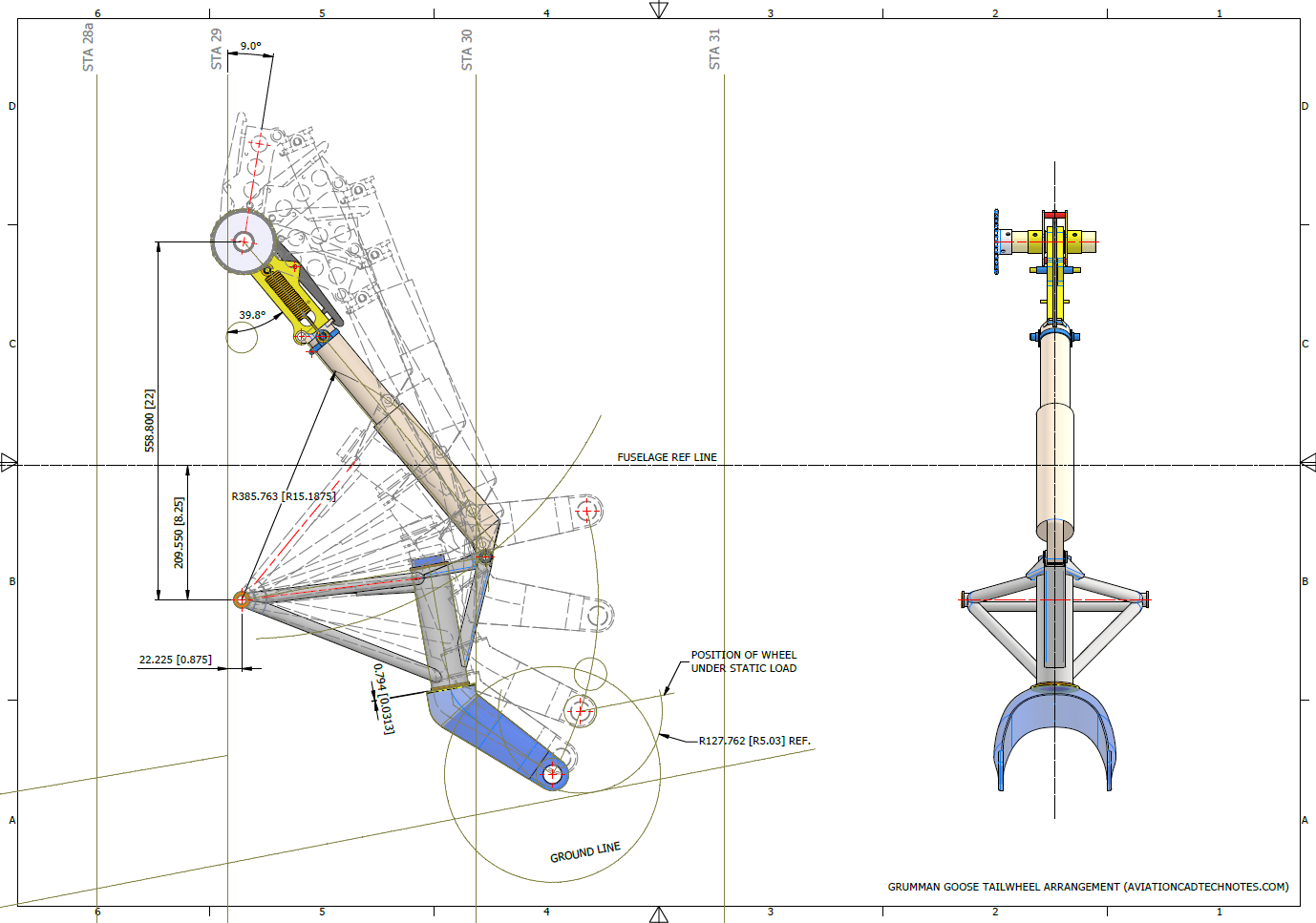
Consider for a moment the following example from the Grumman Goose Tail Wheel blueprints.
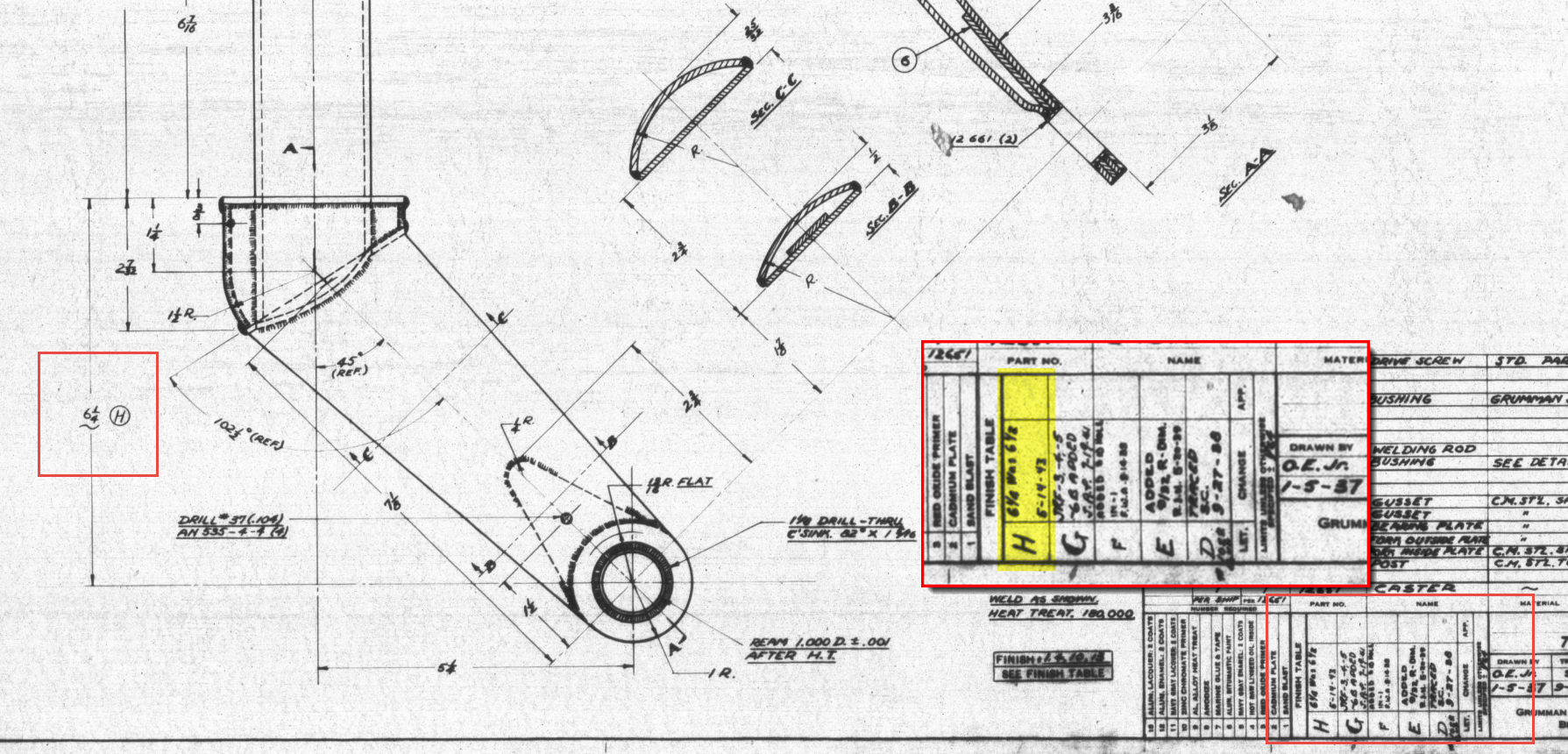
I have intentionally highlighted the revision box to indicate Revision H. This revision specifically documents the change in dimension from 6.5 inches to 6.25 inches. If we examine the other dimensions, the blueprint specifies that the centre axis for the fork should be set at a 45-degree angle. Additionally, the key setting out dimension is 5.25 inches, measured horizontally to the intersection of the vertical axis and the centre of a 1.25-inch radius.
This immediately rings an alarm bell…to achieve a 45 degree fork with the dimensions shown, you would expect that 6.5 inches is in fact correct and that in this case the 6.25 inch is not. But yet it was the only purpose in this revision to record a change to 6.25 inches.
The tilde “~” indicates that this dimension is approximate, but for this to be a revision would suggest that the actual dimension is closer to 6.25 inches than it is to 6.5 inches.
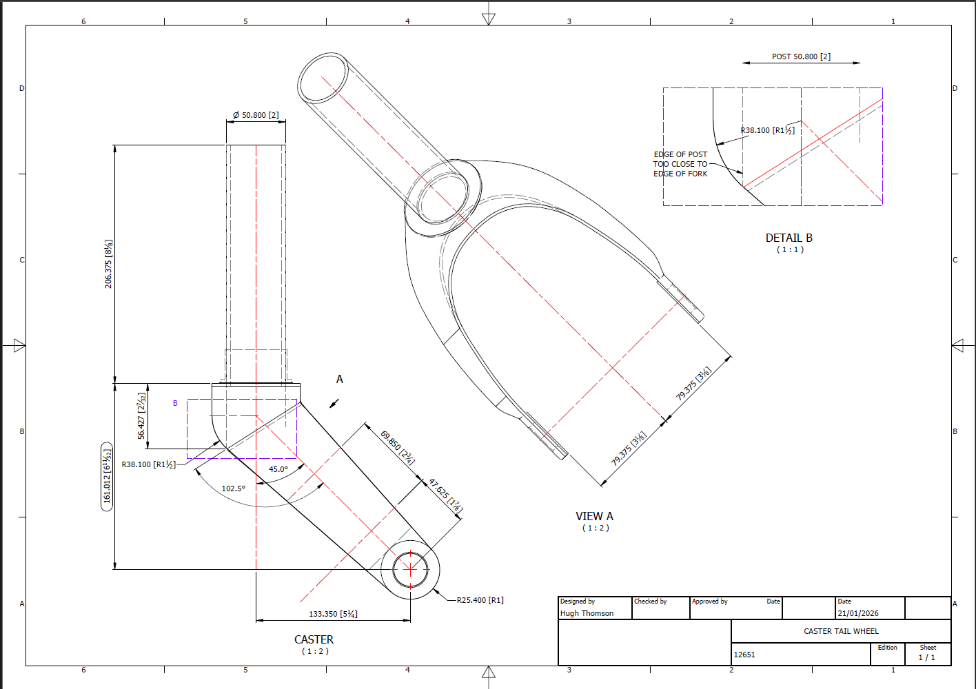
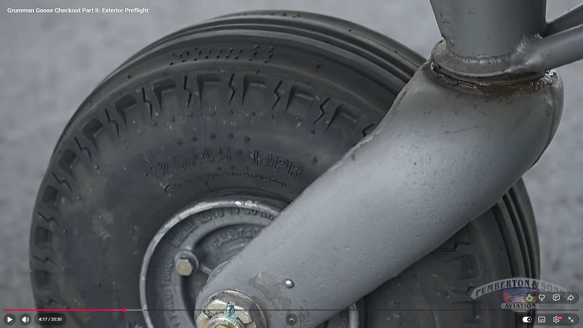
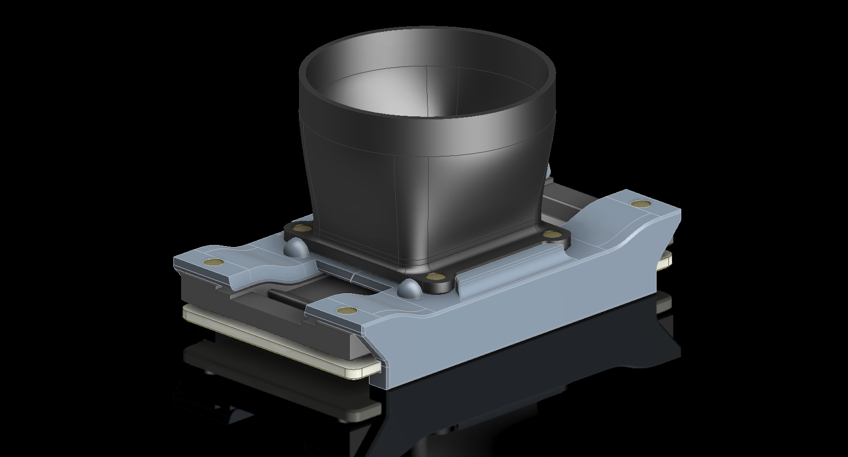
To ensure all key dimensions align with the blueprint, particularly noting that the 6.25-inch measurement is approximate, the setout for the Tailwheel Fork should follow the above depiction. However, we now have a concern: the vertical post is meant to extend to the diagonal intersection and be welded to the curved plate’s interior. As shown in Detail B, the edge of the posts is too close to the fork’s edge, while the blueprint indicates they should be positioned further inward. Additionally, the actual component, seen in the following screenshot, reveals that the heel of the fork is more bulbous than the blueprints suggest.
There was a reason for the 6.25-inch revision, though we do not know it at this time. Therefore, in order for this to be correct and meet all criteria, something other than the 6.25-inch dimension should change.
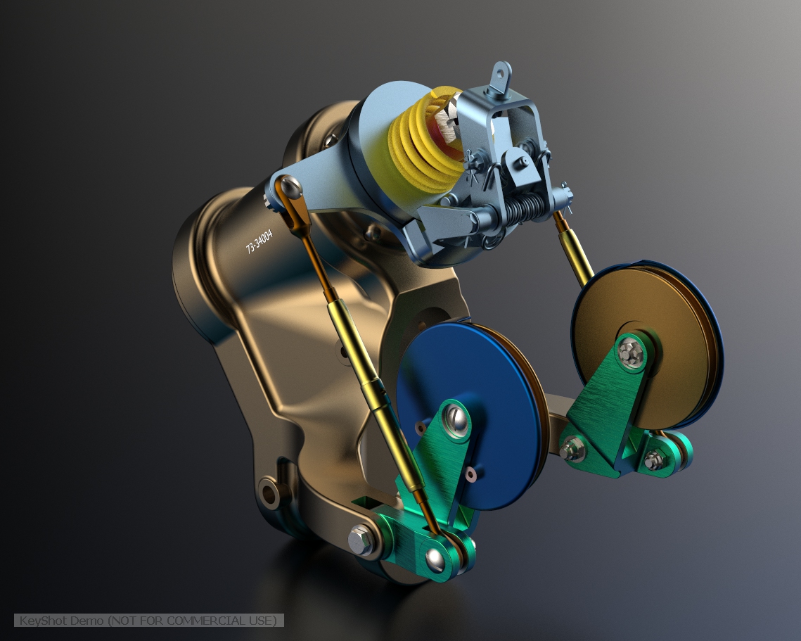
Honestly, I’m not sure what the correct answer is here. Unless I can physically get my hands on the real thing, this will likely remain a conundrum. I will retain the CAD design as it is for now, which serves my intended purpose to demonstrate the deployment parameters of the Tail Wheel and provide clarity on the assembly configuration.
I recognize that the dimensions in most blueprints are generally accurate, with only a few exceptions. When budgets and schedules are tight, it may not be practical to explore entire assemblies in CAD before fabrication. However, in cases where discrepancies are identified, I recommend examining all relevant assembly components in CAD. This will help in identifying the correct solution and understanding all influencing factors before making any changes.


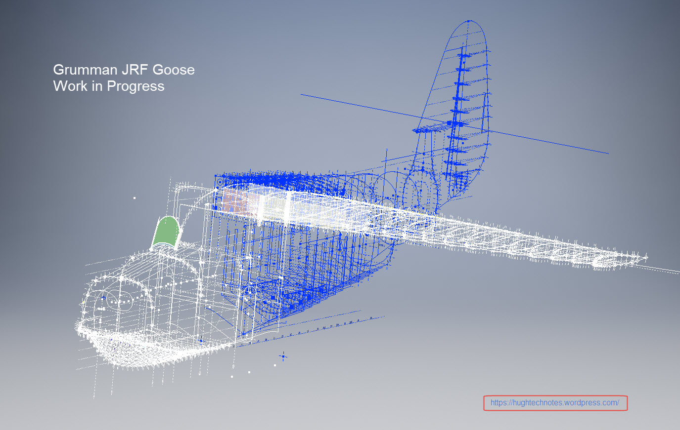
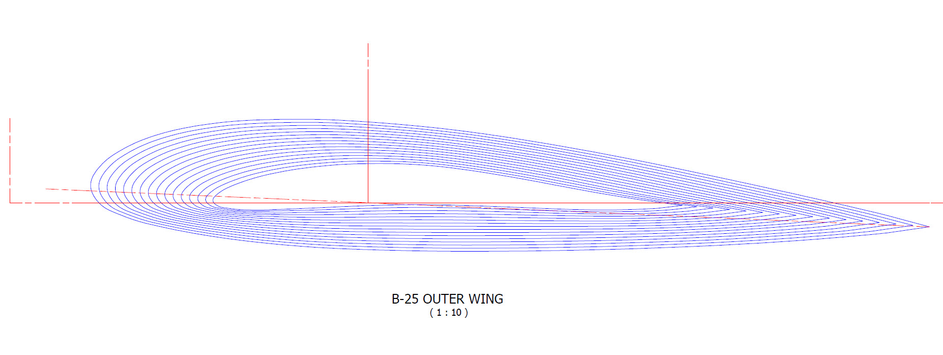
 I seriously think this will make a great foundation for an RC model at whatever scale you desire.


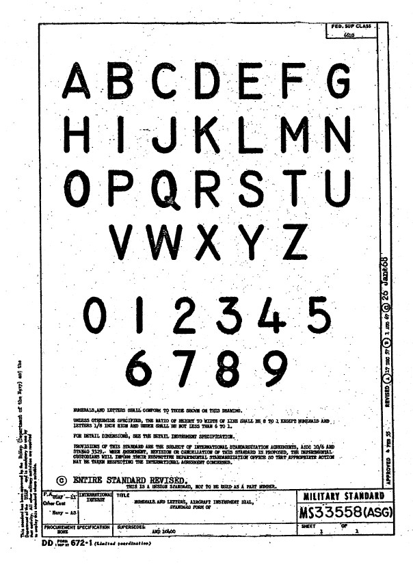 Using this font in CAD systems will result in problems with embossing or extruding.


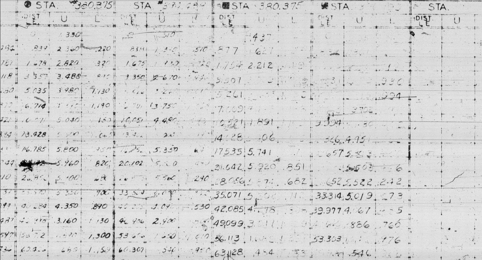
 The full Ordinate/CAD dataset will literally save you 100’s of hours of tedious work and is available online.