P-38 Lightning: Fuselage Update

P-38 Lightning: Fuselage Update

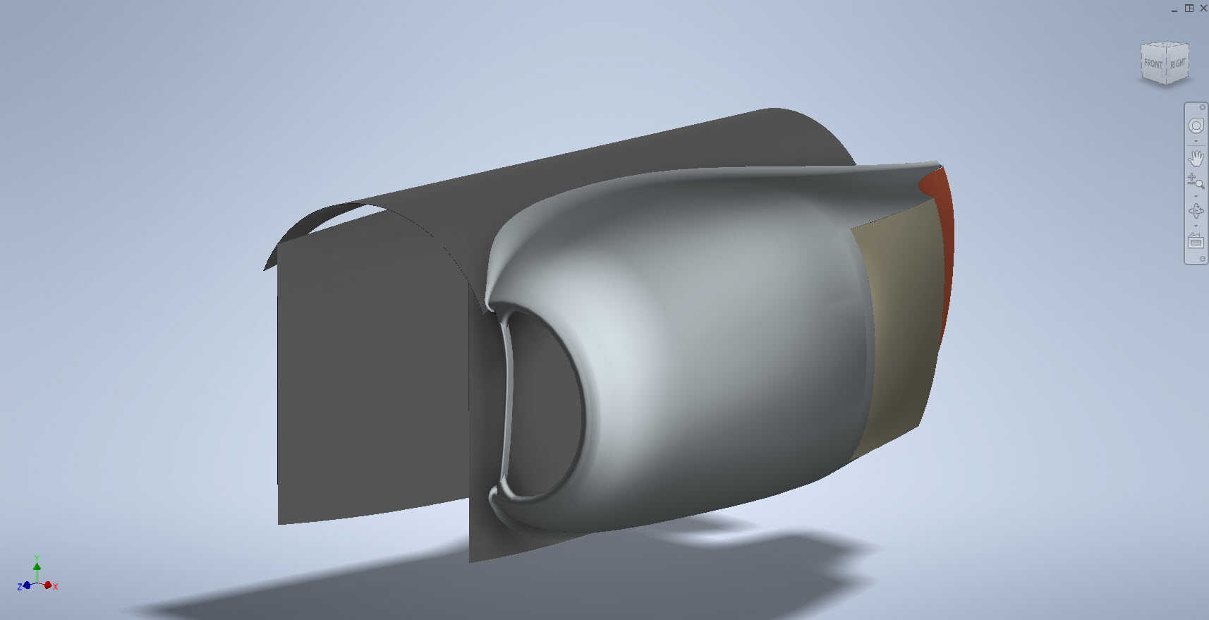
The P-38 Fuselage development has been a real challenge. When I first started this project it seemed to me that the fuselage was well documented with stacks of ordinate information and therefore should be a fairly straightforward model. The front section and the Cockpit enclosure are actually quite well documented but the Aft section and the mid-fuselage section; forward of the cockpit; most definitely are not. After more than 6 weeks this part of the project is still very much a work in progress.

The Cockpit enclosure: There are glass profiles for the cockpit enclosure but they are from the XP-38 early model; which on inspection; in comparison to the little-known information for the later production models suggest they are very close but do vary by 1.2mm but only on the side profiles. I suspect the glass was thickened slightly when they started production. I have to work with what I have and in the absence of sufficient information on the production models’ glass dimensions I have opted for a compromise. As only the side dimensions change with the top profile and interface with the fuselage remaining the same I think working with these profiles in conjunction with the structural elements of the production P-38s will work out quite well.

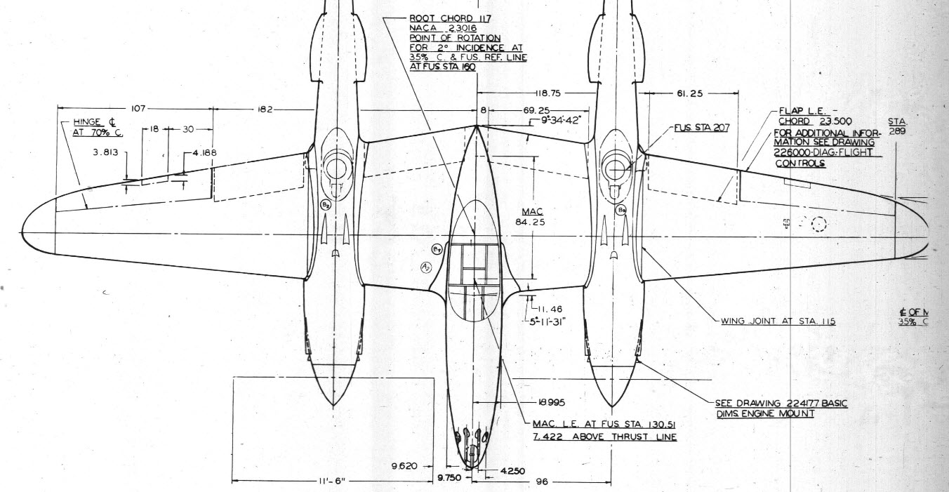
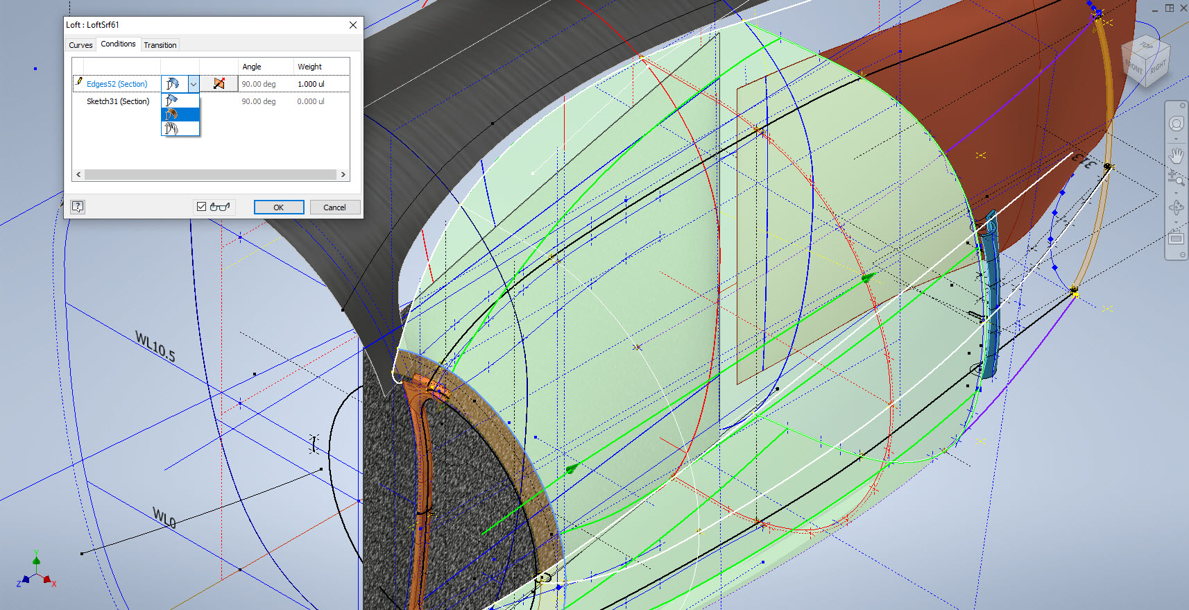
Ref 3rd image: In the 3rd image I have highlighted the location of the profiles at Station 123, 126, and 154. Sta 126 and Sta 154 are absolutely critical in setting out the cockpit enclosure and yet they are not documented nor do we have the drawings listing those dimensions. However, we do have the dimensions at Sta 123. On the windshield drawings, there is a note that states the profile at Sta 126 is the typical profile for the windshield moving forward…logically you would think therefore Sta 126 will match the profile at Sta123. I checked this and it is close but because we also have the glass profile at Sta 126.093 any minuscule deviation will have a profound impact on the curvature when eventually this is lofted. To be sure of maintaining good curvature continuity I lofted all the center section glass profiles and extended the edges by 12mm and then trimmed this resulting profile at Sta 126 and Sta 154. This gave a good result and to check I then swept the Sta 126 profile along the line of the Windshield center line and examined the profile with the known profiles at Sat 123 and of course at the interface with the fuselage. The variance was something close to 0.03mm…that is good enough for me which now ensures good curvature continuity throughout.

Aft Section; As mentioned we don’t have very much ordinate information for the Aft Fuselage Section which will require extensive research of all parts drawings from which we can extrapolate individual points that hopefully will be sufficient to fill in the blanks. The image on the left is a good example where I have drawn the various profiles for the fillet tangent to the fuselage and the wing.

Most of the drawings for the Fillets include the Tangent Points for the Fuselage and the Wings which I included in the model that now collectively gives us a reference line for the side of the Aft Fuselage at the top and bottom of the wing. Each fillet curve was checked against the ordinate surface for the wing and adjusted accordingly taking into account the skin thickness; these were also checked against known bulkhead profiles in this area.

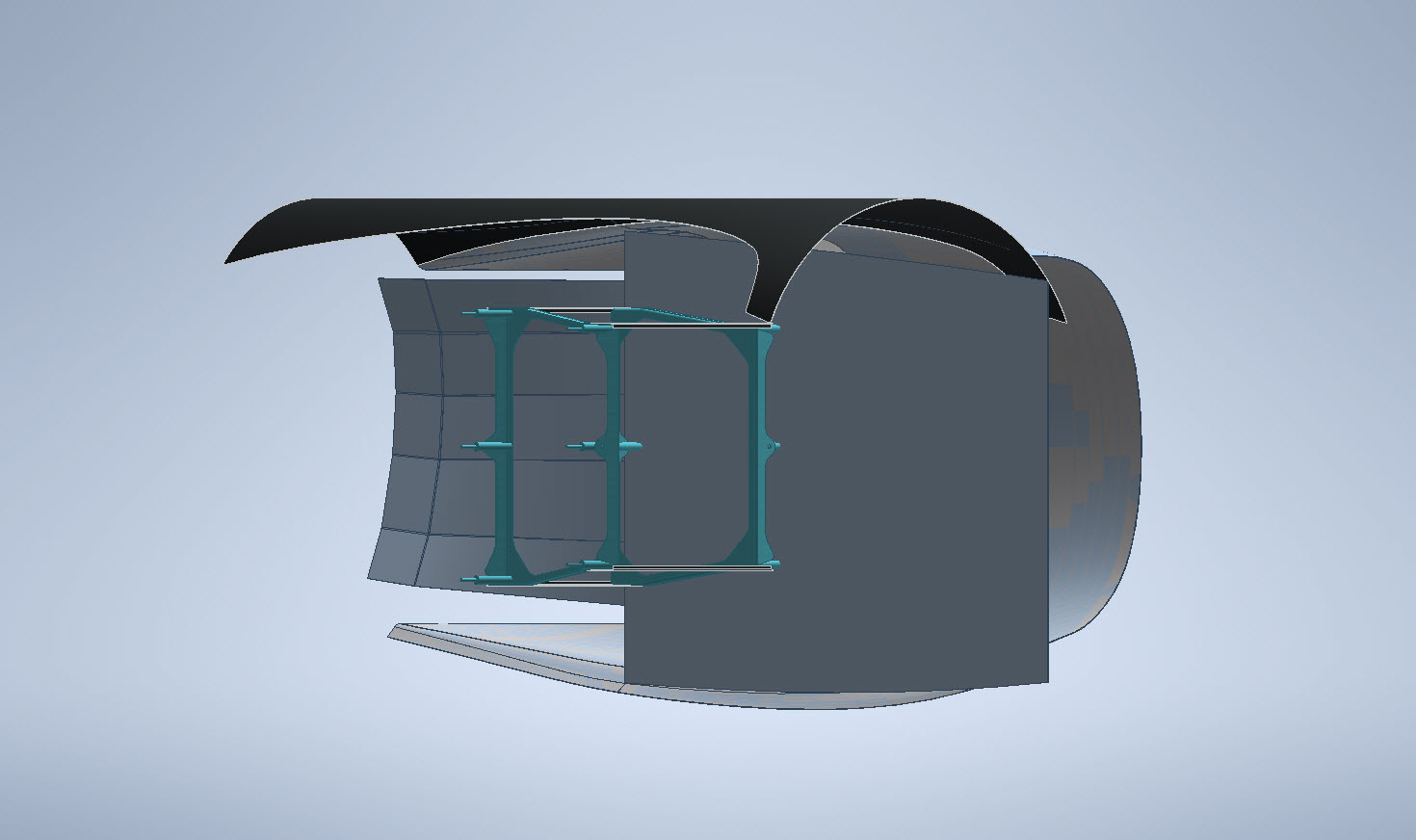
The second image; on the right; shows how we can also use the main longitudinal members in a similar fashion to help ascertain key dimensional information to assist with the development of the aft sections. The red lines are the longitudinal members where the part drawings contain relative dimensions to the Fuselage reference line and the Centre of the Ship. Again each of the dimensions was checked against known bulkhead profiles where the average variation was in the order of 0.012mm. It may seem too small a variance to be of any consequence but when I later have a need to use these lines when creating the surfaces they have to be exact…so in each case the point was adjusted to be an exact intersection with the bulkheads. Inventor is very fussy when lofting with a guideline with no room for error…so this has to be exact.

Ultimately the goal is to find as many part drawings as possible with dimensional information that I can use to eventually have enough data to build the relevant missing Aft Section profiles. Typically this will be the main longitudinals, the skin parts, and of course the fillet drawings. This is painstakingly slow work as virtually every part drawing in this area is being reviewed for potential data that will help me achieve this goal and there are a lot of drawings!

Similarly, the process will be the same for the fuselage area forward of the cockpit which again sadly lacks a lot of key profiles. The research is where the time is expended in developing these ordinate sets…so far for the fuselage alone, I have spent in excess of 6 weeks of continuous work to get to his point, and still a lot to do.
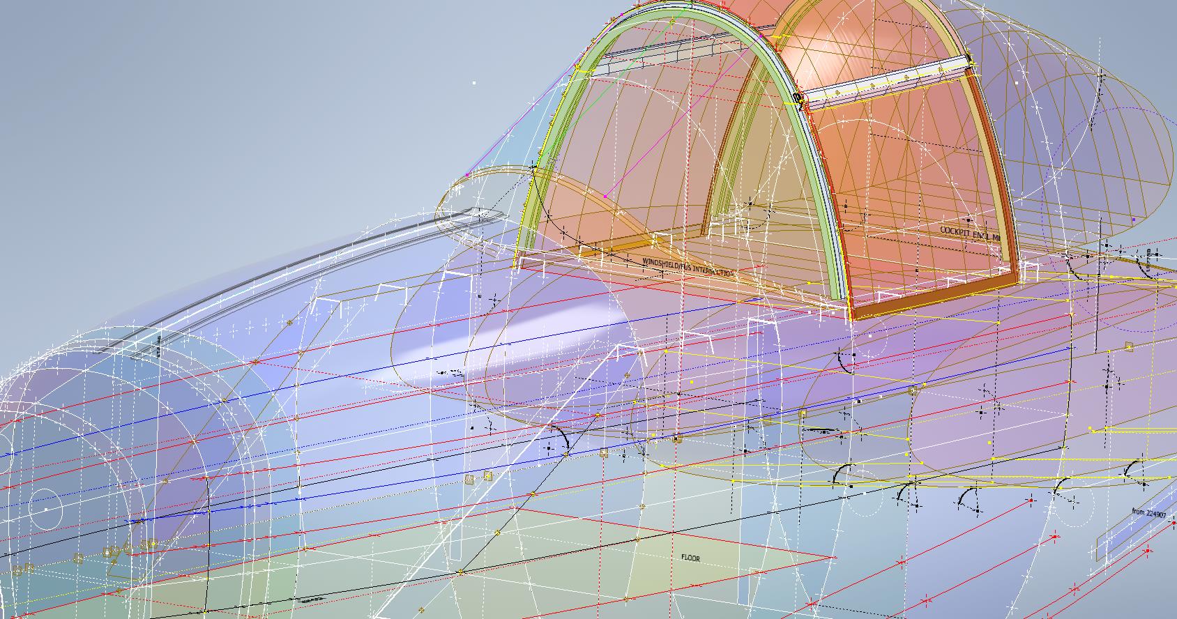
Finally, both the P-39 and the P-38 ordinate dataset models are updated with a new approach to how these datasets are being built. I still have the extensive Excel spreadsheets listing all known dimensions but for the model, each ordinate profile is now inclusive of a surface patch. What this means is that conversions of the model for use in other cad systems will now provide a surface plane as well as a sketch profile which helps the model builder very quickly create the bulkheads for these scale models.

The P-38 is almost complete with the Boom, Wings, Horizontal and Vertical stabilizers, Flaps, and Ailerons all modeled and recorded. The Landing gear is almost fully 3d modeled as well…which is great for those that are keen on super detailing their RC models. These models have also proven to be enormously useful for the Restoration groups one of which I already work with on a P-39 Airacobra restoration.

Update 14th June 2023:

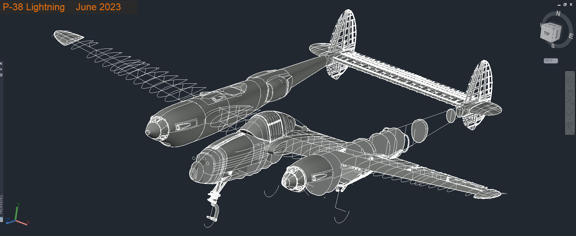
I have been developing the key Aft center profiles at the top and lower part of the fuselage. This is actually quite exciting stuff as there are not a lot of pertinent ordinate dimensions for the Aft Fuselage so I resorted to building profiles from individual part drawings.

For each part sketch profile, I have extrapolated various curves to determine the center work points. What is exciting about this is the eventual lower fuselage curve (in magenta) is absolutely perfect…normally when you derive work points from half a dozen different parts in inches there is an expectation that the eventual curve would show the odd deviation…but it didn’t. The curvature analysis shows this to be absolutely spot on.
Update 23rd June 2023:

Fuselage Aft Assembly: Almost finished with the ordinate study for the fuselage Aft assembly. This work involved generating cross-section profiles from stringers, longitudinals, bulkheads and fillets to derive series of points from which to build the curved profiles. Each profile built is checked against the existing ones by lofting a new surface profile, then a sketch cross section generated to check the curvature maintains alignment with the existing profiles. This is done for every newly generated profile. Ultimately I will end up with the best-fit surface for the Aft Fuselage Assembly. All new points will be recorded in the Main Spreadsheet and fully dimensioned on individual drawings.

New Website Address

New Website Address

This blog web address has been changed to Hughtechnotes.com (was previously Hughtechnotes.wordpress.com). The new address is domain mapped so even using the old address you should still arrive here. If you have any problems then please drop me a line at hughtechnotes@gmail.com or general feedback or comments.

By the way to make your experience more enjoyable and distraction free this blog is now Advert free… which means I pay extra for that…so please consider a small donation to help with these overheads. Thank you.

Technote: P-38 Forged Parts

Technote: P-38 Forged Parts

I had promised an article on the P-38 Flap CAD development as a follow-up to my earlier article on this topic…but I deviated slightly to address a question from a reader about Forged Parts.

Typically for all these aircraft Forged parts are the main element in the process of manufacturing complex parts that may be used in such applications as Landing Gear. Such is the case with the P-38 Lightning where we have the main support members that are machined forged parts.

I have touched on this briefly in previous posts: Technote P-39 Inventor Face draft and P-51d Mustang Tailwheel Down Position support. Those articles tend to focus on using the Face draft feature in Inventor and using Derived model parts to differentiate between model states i.e. Forged and machined. I should note that with the later versions of Inventor, it is possible to contain the various Model states in one part file but I prefer to use separate derived Part files. The reason is that they are in fact 2 very different manufacturing processes and the drawings for each model may be sent to different departments or indeed different companies. So it makes sense to keep them separate.

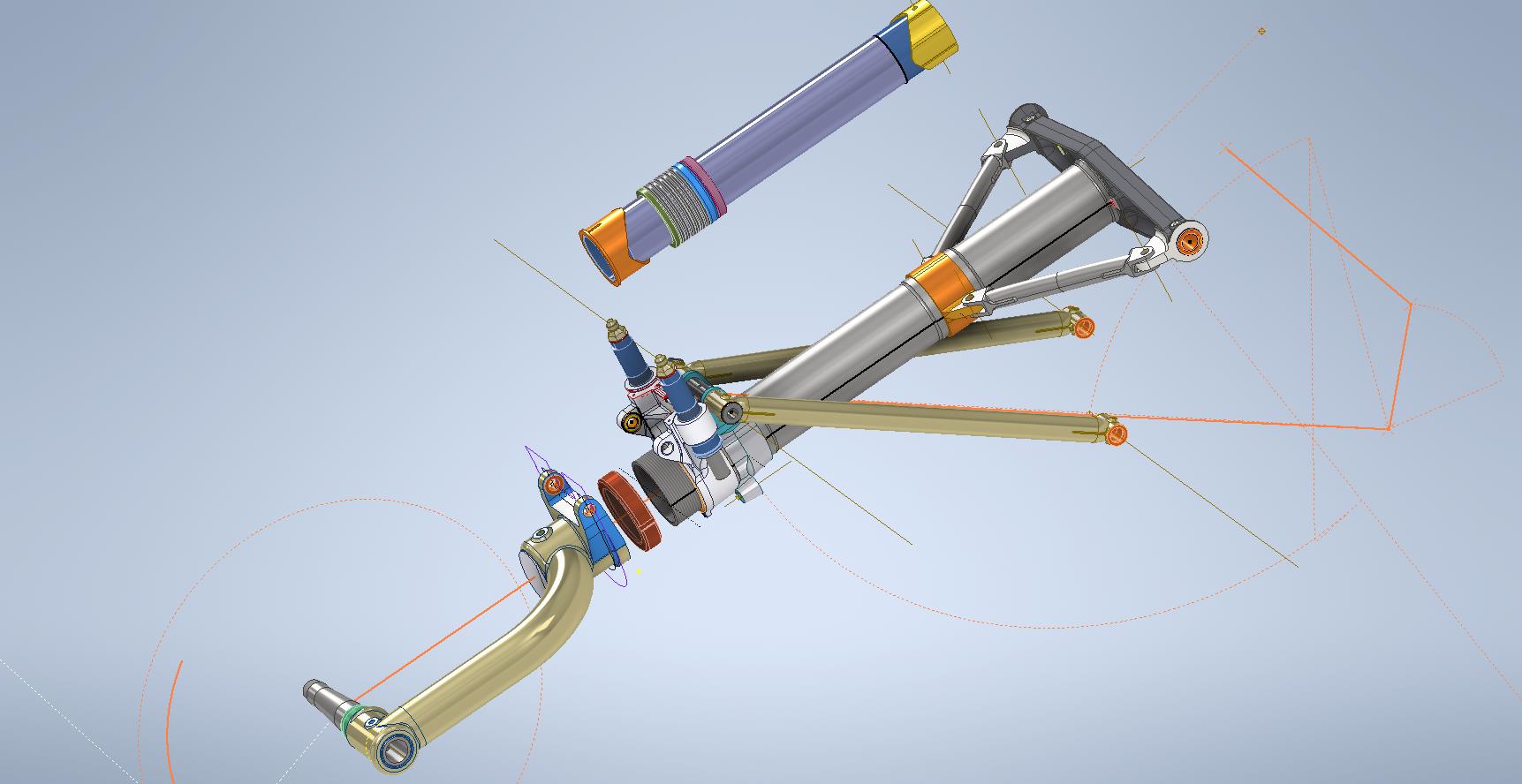
In the example above we have 2 components for the Main Landing Gear and the Nose Landing Gear. Both examples use the derived parts process as you can see. In this article, I wanted to cover some of the frustrating differences that you will likely encounter when building these models.

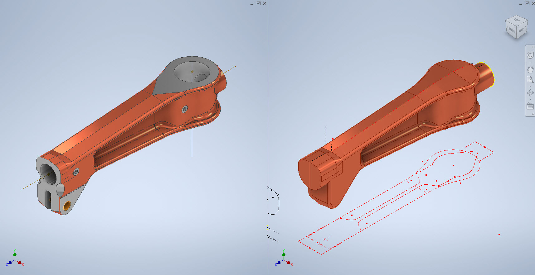
Forged Parts are notoriously complex and the Lockheed drawings tend to only provide the main dimensions and key elements often omitting small details that are likely to have been decided by the mold maker. To determine missing details I often build the models as a surface and then turn that into a final solid.

In the above images, this part had an elevated top and bottom section interspersed with a waveform for the main body. The 2d sketches were drawn outside the main part body to make it easier to visualize and manipulate the part data. This part used 3d intersection curves to generate a sweep path for the top and bottom profiles and the surface trim command to profile the main body.

Incidentally, although the sketches do not share the same space as the main model you can still select a single line from any of the sketches in order to trim parts and surfaces in the model…they do not need to be connected. I have often seen folks extrude surfaces from external sketches and then trimmings to that surface but you don’t have to do that…just select the line.

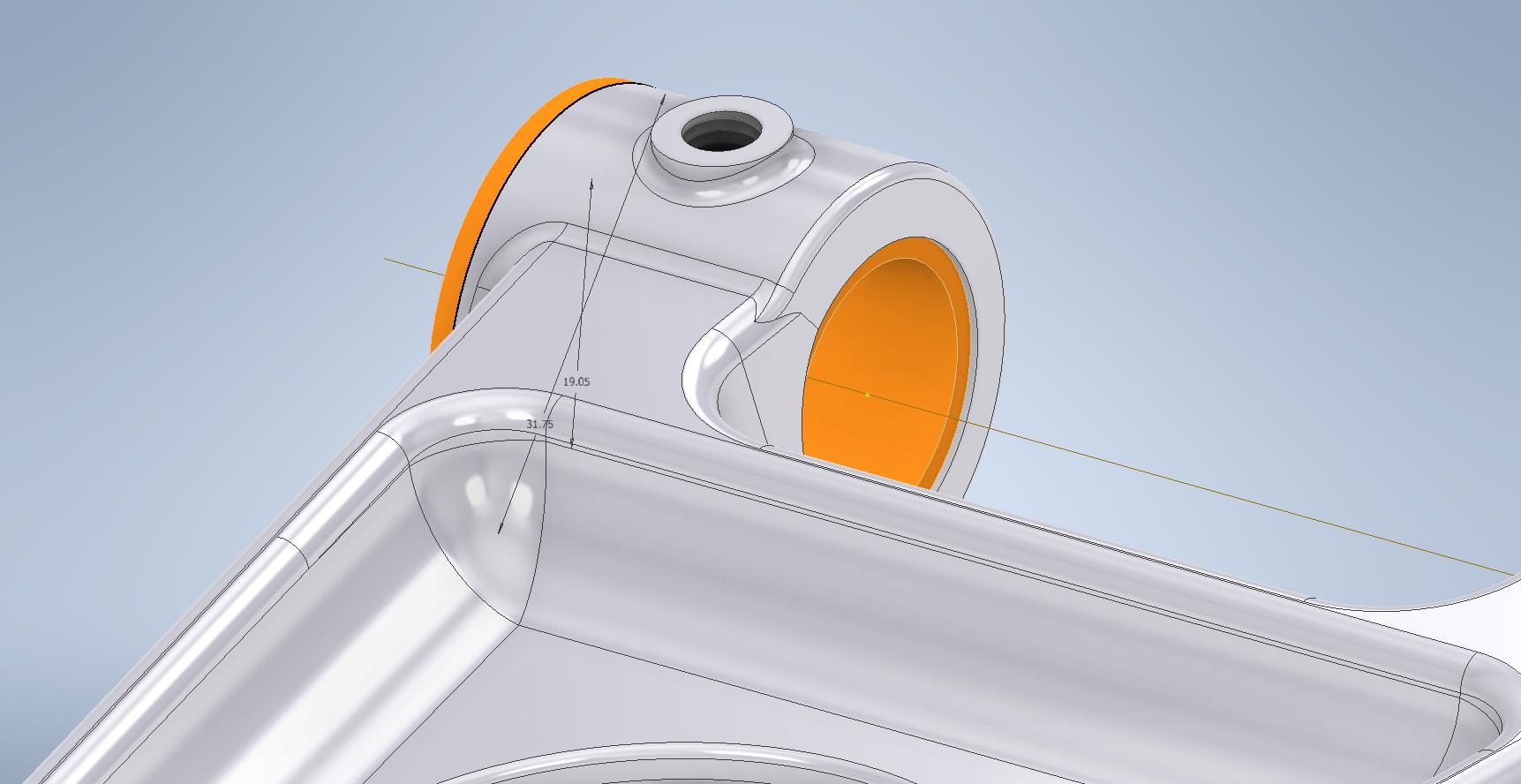
One of the key details that is not clear in this particular example was the protrusion just above the cylinder at the front of the model. All you have on the drawings is a line on elevation and 2 lines on the plan sketches..the specific details of how this small detail interfaces with the main body is down to interpretation. I modeled it with the flat upper surfaces tangent to the curved edge and applied a fillet to the intersecting sides. I did look at a number of variations but I think the end product is close to how it will actually be. This is the frustrating bit when trying to decipher designer intent with limited information.

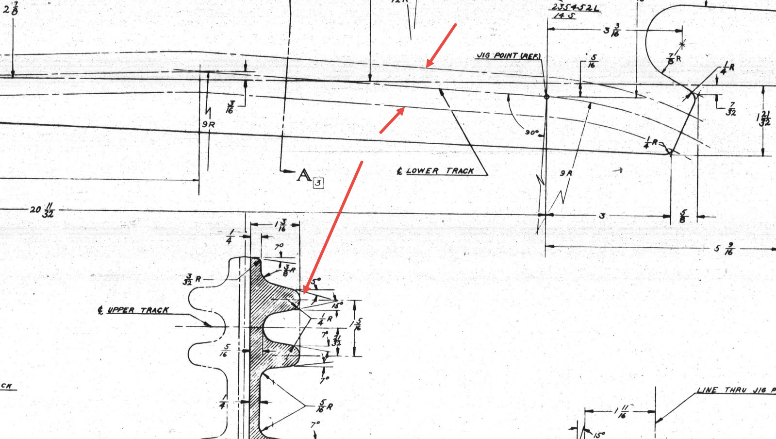
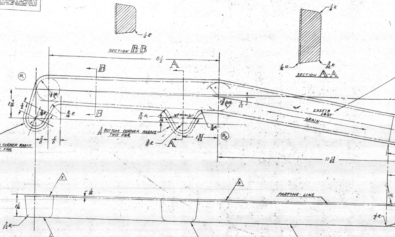
Some of the complexity comes from how the drawings themselves depict the dimensions of the profiled sections. In the first image above we have the criteria shown as the center line of the section’s curved profile. The second image shows a different part however this time the dimensions are to the projected edge intersection of the curved profile. The third image is also similar where the dimensions shown are to the projected intersections. The final image is the Flap carriage arm with the dimensions shown to a dotted line which is not clearly defined on either the sections or the main views to determine what this actually is. After much deliberation, I deiced to interpolate this line as the projected intersection of the drafted sides with the top and bottom faces. I had initially suspected this was to the corner tangent but that would entail a very complex development process due to the varying corner radius.

As you look through the dozens of forged part drawing there are all sorts of variations on the theme with few consistencies. This is where you can spend a lot of time determining how these dimensions relate to the model and how best to incorporate this information in such a manner to keep the model as simple as possible. Consequently, it is not unusual to spend upwards of between 3 and 4 hours modeling the forged parts. I think for the most part where doubt exists to work to a projected intersection as the point of dimension…it will be a lot easier to model and saves a whole lot of frustration.

To give you some idea of progress on the Nose Landing Gear models:

In the latter 2 images, you may notice small differences which relate to the various model variances. I am modeling the P-38H and the comparison photo is the P-38J.

TechTip: Variable Fillets:

When modeling these complex parts often applying fillets can yield unexpected and undesirable results.

In the images above you can see how applying just standard fillets of different radii can result in quite an undesirable intersection between the flat plane and the circular node. What we need is continuity to achieve a smooth transition from one edge to the next as shown in the second image above. This can be achieved by using the Variable fillet feature.

Variable Fillets give us the option to vary the radius of the applied fillet. When you first apply the Variable Fillet you have a radius specified for the beginning and the end of the selection…you can apply additional points anywhere along the length of the selection to which we can adjust the radius at those points.

You can also add selection sets of edges to the original selection which have their own capacity for separate adjustment. To achieve our goal here for fillet continuity I have 4 selections: the top planar edge (1), the node circumference (2), the lower planar edge (4), and the remaining node circumference (3). It is important for each selection set fillet to have the same radius at each intersection to ensure continuity.

Each selection set is listed separately in the dialogue box and the way to adjust them is to simply select the edge selection as I have highlighted with the first one…this shows the applied points and values in the area below under the heading “Variable Fillet Behaviour”. I have added additional points to the planar fillets at 1 and 4 where the value is set to 2mm which then defines the radius between those 2 points. A small point worth noting is the diagonal draft parting line on the face of the round node that prevents selection continuity which is why we have 4 selections and not just one continuous.

It does not take long to do this and the end result is much more agreeable.

P-38 General Updates

P-38 General Updates

Just a quick update to share new and updated assemblies for the Wing Flaps, Centre Section Flaps, and the Horizontal Stabiliser.

This post was intended to be a detailed overview of the Wing and CS Flaps but I was keen to share progress on these main assemblies. I will revert back to the flap discussion in my next post.

An interesting point worth noting is the color coding for the Horizontal Stabiliser and Elevator. The Red ribs are exclusive to the forward Horizontal Stab area, and the Yellow Ribs are where the internal Horizontal Stab ribs and Elevator ribs share the same alignment.

For the flaps, the main surfaces shown represent the cutout in the wing ribs…the information for this is rather sketchy but more on that in my next post.

Each of these new assemblies also includes new Basic Geometry fully dimensioned drawings in DWG and PDF formats. Soon to be added to the P-38 CAD/Ordinate dataset, drop me a line for details or check out the CAD Resources tab at the top of the page.

.

.

Technote: P-38 Lightning Flap Guide Tracks

Technote: P-38 Lightning Flap Guide Tracks:

The P-38 project is a study I have been working on for a while. In previous posts, I have covered the development of the Boom, Empennage, and Dive Flaps…even did a video on Youtube for the latter. Many of these studies are designed to research the operational characteristics of the component parts and this new study of the wing Flaps is no exception.

Essentially the flaps are split on either side of the Main Boom, with one being fitted at the Centre Section and the other at the main wing. These are activated by hydraulically controlled push and pull tubes with preformed carbon steel cables.

The extent of the operation of the flaps is controlled by guide tracks at each end, which incidentally is where this part of the project starts.

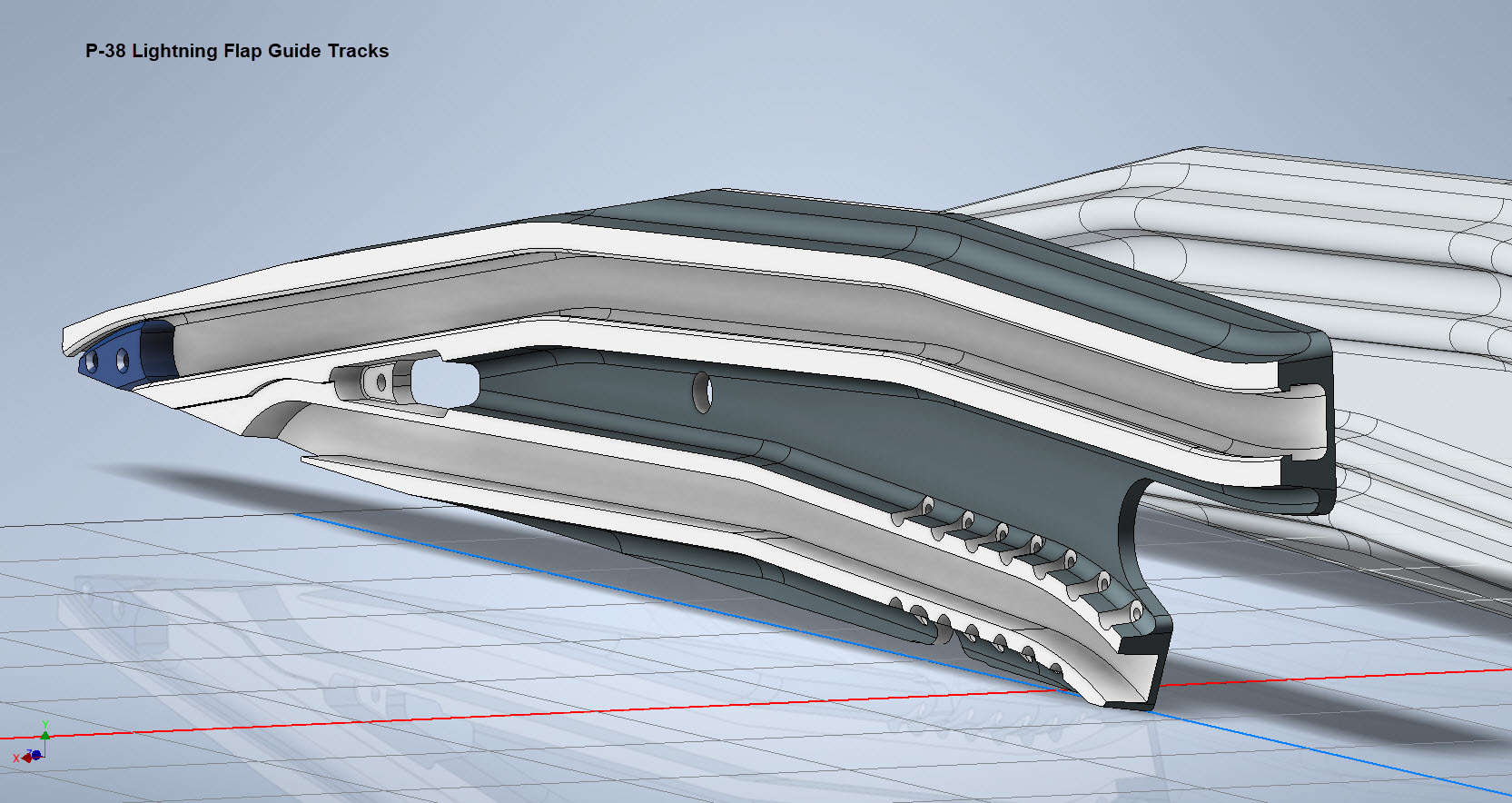
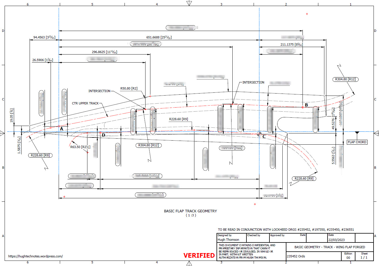
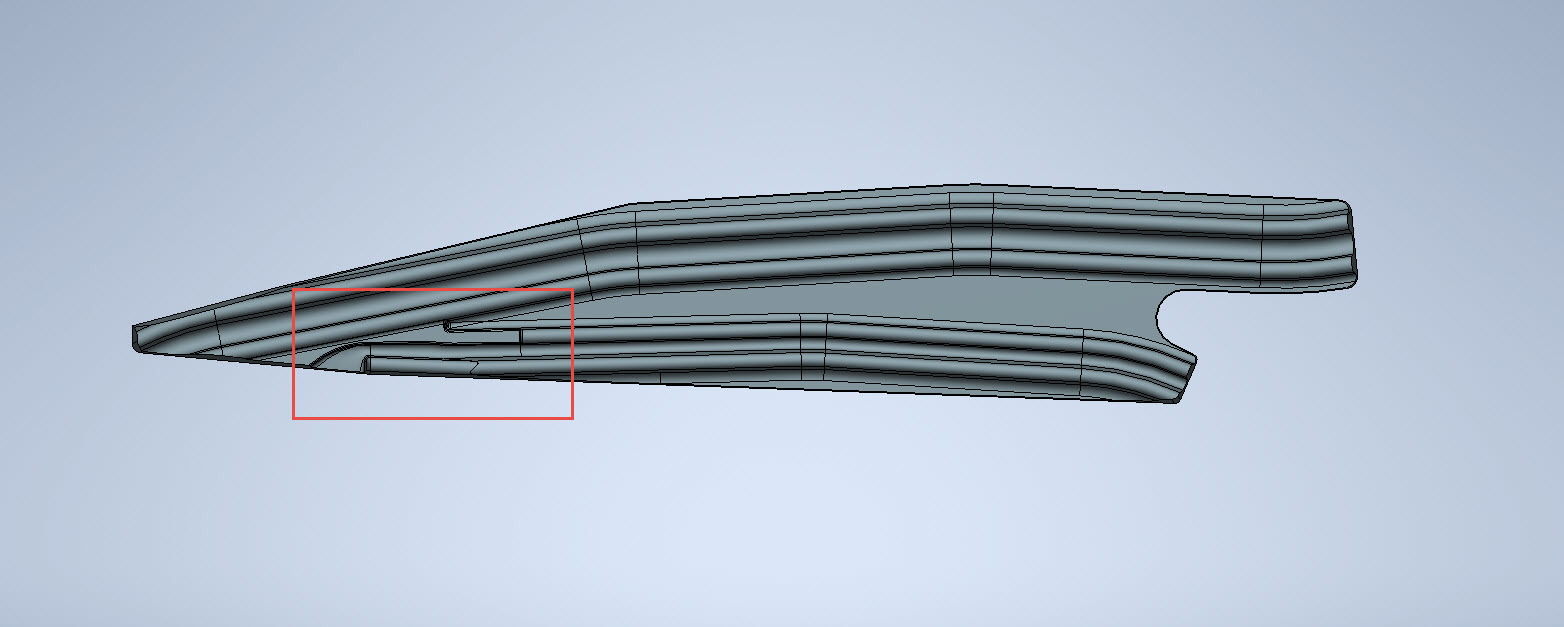
These guides are machined solid from forged Alumimiun blocks. In the image above the machined part is shown with the original forging in the background. It comprises 2 tracks with the upper track just over an inch wide and the lower track slightly smaller at 0.835″ wide. The blue part at the extreme end is a separate stop block.

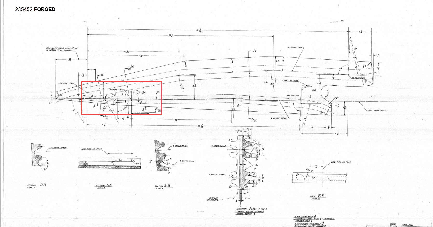
I am currently working through the variations of these tracks for each location and although some minor differences they are all based on one type of forging, part #235452.

The forging drawing is not too clear about the definition of the track at the left-hand side which appears to drift slightly from the main track center. Understandably the lower part of the track walls deviate to align with the edge of the forging and therefore the main upper wall portion will adjust accordingly. I have improvised in developing this area and now that the project has further progressed there are a few minor changes I would make should this part ever be required for actual production. At this stage, my primary objective is the operational characteristics that are unaffected by this as the end product is the machined component that is derived from this forging.

Update: 26th March 2023:

Making good progress on the Wing Flap mechanism with the Carriage Assembly now complete except for a few standard AN nuts and Washers. The Carriage Assembly also shows the track surfaces to demonstrate the correct relationships between the rollers and the track.

The second image above shows the adjustable roller at the front end of the carriage. This is achieved by the use of an eccentric bushing item #221832 which fits into the retaining locking ring item #221741 at increments of 30 degrees.

Update 30th March 2023:

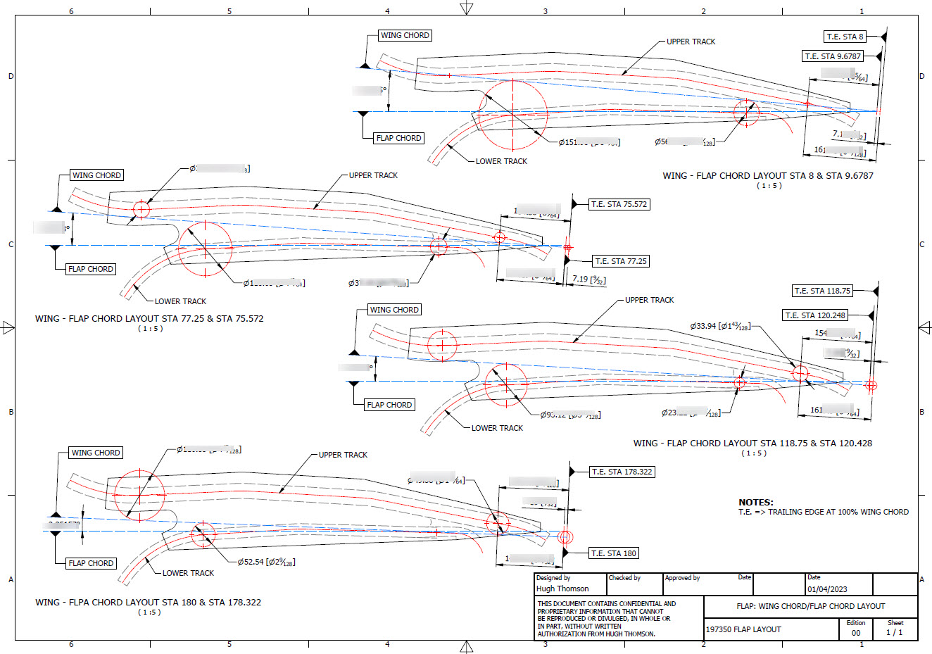
Have spent a considerable amount of time researching and resolving macro dimensional variation for the Flap Track guides. When I talk about macro I am looking at close to 1/128″ or 0.2mm…but it is essential to get this correct. The dimensions are blanked out for obvious reasons as this stuff takes a lot of time to research and develop.

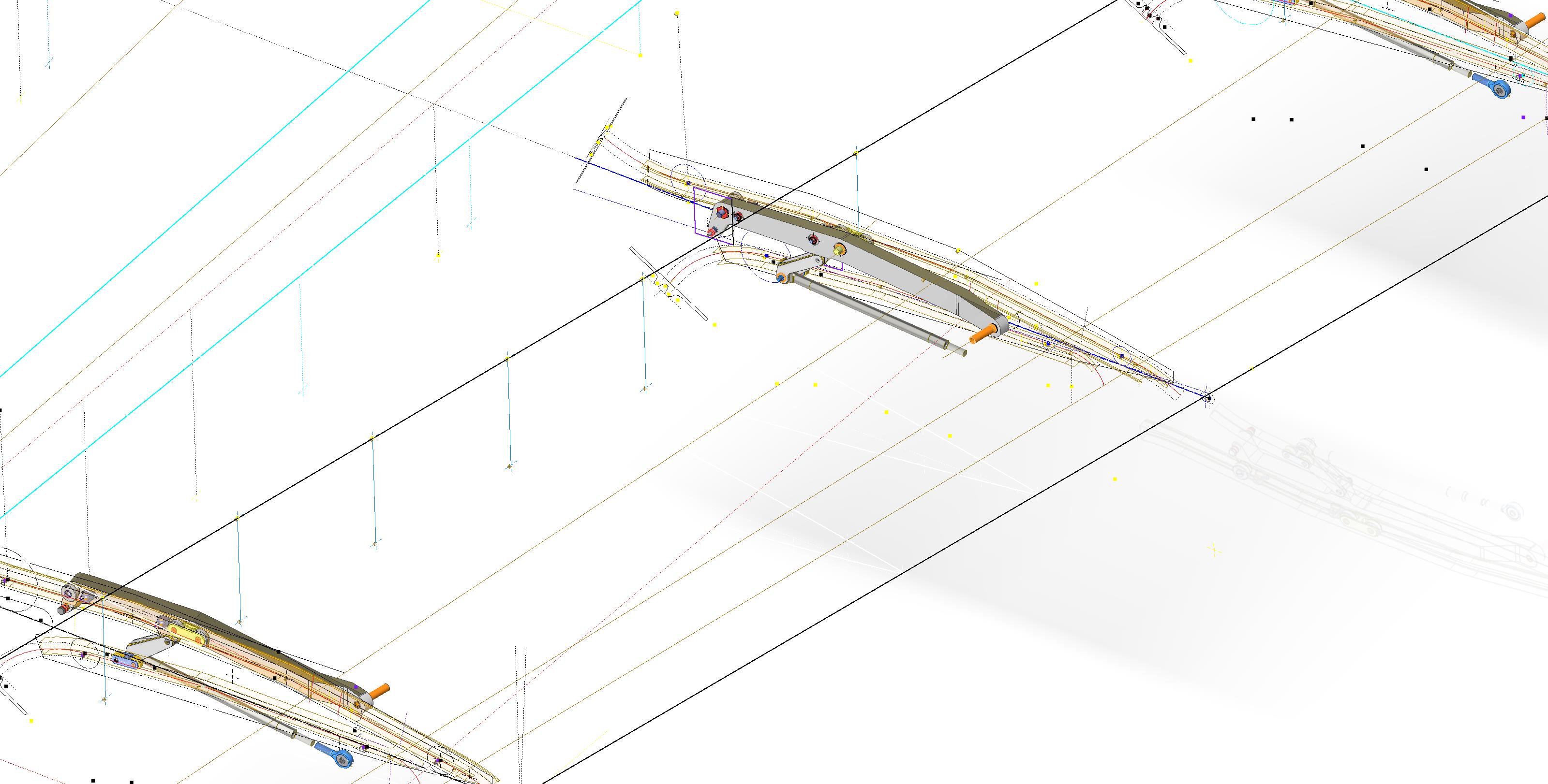
Finally located the Flap Track assemblies in their exact position on the wings. I will actually build the final assemblies as 2 separate items; one being the Inboard Flap and the other the Outboard Flap. For now, the initial plan was to get to a point where the tracks are accurately positioned and ready for the next phase which will be the Flaps themselves. The final stage will be a working simulation to determine operational parameters but we are a long way from that goal at this time.

The tracks are currently shown in the assembly as surface models which keep it simple, however, when I get to the stage of finalizing the assemblies this will be fully modeled. This part of the project was surprisingly complex to achieve and every dimension has been cross-referenced and checked against known data…at one stage I had over 21 drawings one at the same time.

To help establish the starting point for the Flap Crriage I have an outline sketch of the key runner positions to which I later constrain the carriage parts in an assembly. It is actually quite a useful technique to use sketches to help establish relationships when building an assembly.

In summary, it is often beneficial to use surfaces in lieu of solid models for clarity when building these types of models as it is so much easier to see the key relationships between the main elements. Also using sketches to help align component parts in an assembly is a good work method and can also be used later when creating 2d drawings.
This more or less covers the basic setup for the Flap Tracks and carriages…the next article will focus on the Flaps and the eventual final wing Flap assembly.

.

.

.

Technote: P-38 Lightning Dive Flaps

Technote: P-38 Lightning Dive Flaps

This is what I am working on now: the P-38 Lightning Dive Flaps. At the moment this is a multi-body part file which I will then extract as separate parts and then assemble. The plan is to also include all the mechanical components to analyze operational criteria.

I shall add to this post as this part of the project progresses and perhaps add some notes on Simulation within Inventor. I should note that the external panels are actually transparent to show the internal lightening holes depicted in these images.

Update Dec 7th 2022:

The mechanical components are now modeled and temporarily located in the Dive Flap assembly. It is actually quite a substantial mechanism that is currently missing the main hydraulic operating cylinder. That component is a contracted supply unit for which I do not have any details so the simulation will use a proxy component for purposes of evaluation.

Before I get around to doing that I must first locate it on the underside of the wing…that will need to be partially modeled with local ribs and struts in order to define the fixing bolt locations.

Update Dec 8th 2022:

Another day, another update. I now have the rib at Station 146 and 158 modeled primarily to assist with positioning. The Lockheed layout drawing for this assembly is not included in the archive so I had a lot of research to do to get this thing in the correct position. What I noticed is an access hatch on the underside of the wing which this assembly effectively replaces so that was useful in this task, though I had a lot of rivet holes to position to get it right!

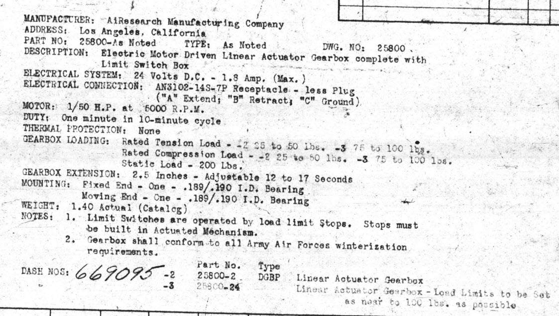
You will notice that the assembly now has the operating cylinder…I was lucky to find a drawing for this that provides much-needed data for maximum and minimum travel. Actually, I call it an operating cylinder but technically it is a linear actuator gearbox.

When I inserted this item into the assembly it provided a positional check on the main assembly.. which incidentally was perfect.

A few bits to tidy up and then move on to a simulation…I shall upload a short video to Youtube when that is done.

Update 9th Dec 2022:

I have cobbled together a quick video showing the operational aspects of the P-38 Dive Flaps. I am working on a more detailed video which won’t be ready for a few days…so check out this short version for now and let me know what you think.

https://youtu.be/95d8tc3wd14

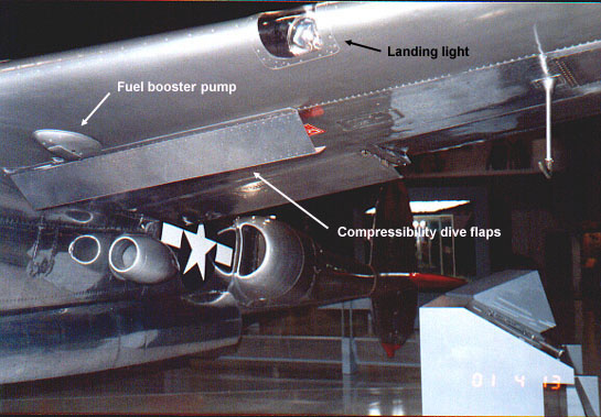
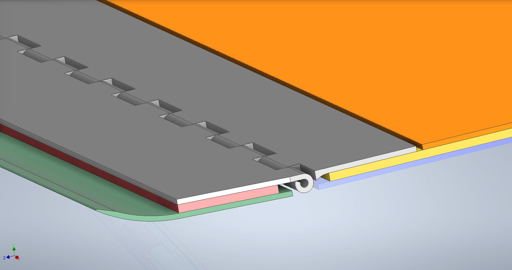
The technical bit: Each of the 3 flap panels comprises 3 layers of sheet metal with a total thickness of 0.18 inches or 4.572mm. The mechanical assembly is fitted between Ribs at Station 146 and Station 158 and driven by a Linear Actuator. The Dive Flaps were designed to be retrofitted to P-38 Lightning prior to P-38J which explains the location of the main support frame which aligns with the hole centers for a wing access panel and the forward panel fitted forward of the main beam. For reference, I have included a selection of design operational data and some close-ups of the mechanism. that you may find interesting below.

.

.

Technote: P-38 Lightning Wing Tip

Technote: P-38 Lightning Wing Tip Development:

Developing this wing tip turned out to be more complex than I originally thought it would be. Because the model required a few interesting techniques I figured it is worthy of a quick technote that hopefully will assist others.

First, off the bat, you will probably have noticed the center partition which came about as a consequence of the development process. I will try to explain how this transpired…read on for more details.

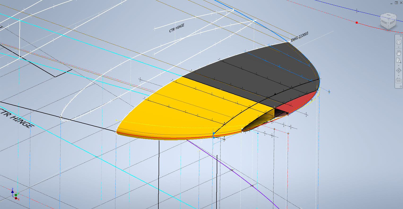
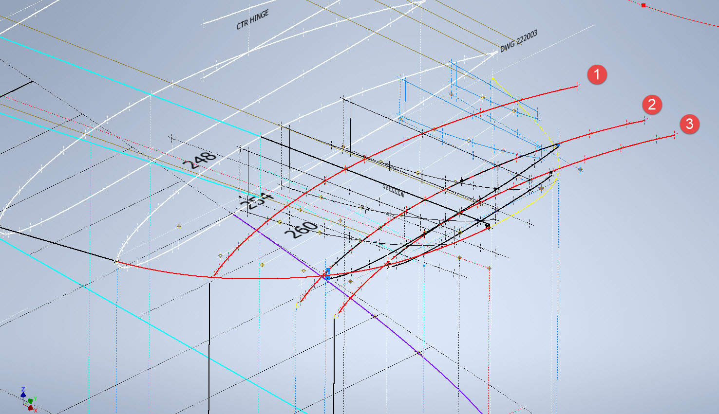
What we have is essentially one main rib profile at Station 289 and 2 others towards the tip which you would normally just loft to achieve the finished surface assuming that the required outline guide rails were included in the initial data set. Actually in this case we didn’t have those curved outlines as a 3d profile only a 2d outline on the plan view. Even with the guide rails in place just lofting the full rib profiles did not work due to the continuity of the rails in a circular manner that prevented a successful loft.

By the way, the circular guide rails at “A” and “B” were generated as intersection curves using a side profile (top right in the background) and the plan profile to derive the resulting intersection lines. I initially wanted to extrude the 2d plan profile and build a 3d curve on the face of the surface but I was unable to apply a tangent constraint to align with the Leading and Trailing edges…so my only option was a 3d intersection curve.

Realizing that a full rib profile loft was not achievable I decided to fill each rib profile with a patch surface and then split the surface at the main beam intersection, which incidentally is perpendicular to the ribs. So this gave me a patchwork of surfaces fore and aft that I used as surface profiles and lofted each section as shown using the guide rails at “A” and “B” and the center rail at “C”…this created the partition I mentioned in the beginning.

Once the main fore and aft sections were modeled I then proceeded with the extreme tip which was simply a case of again adding a surface patch to the small projecting profile in the center and lofting the surfaces separately as before. Occasionally when you have problems with lofting it often helps to break it down into more manageable chunks.

Accuracy is extremely important to ensure a good surface finish with no small deviations or folds. So I checked the coordinates of each profile mathematically and adjusted the dimensions accordingly for the top surface.

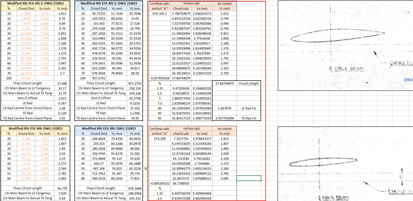
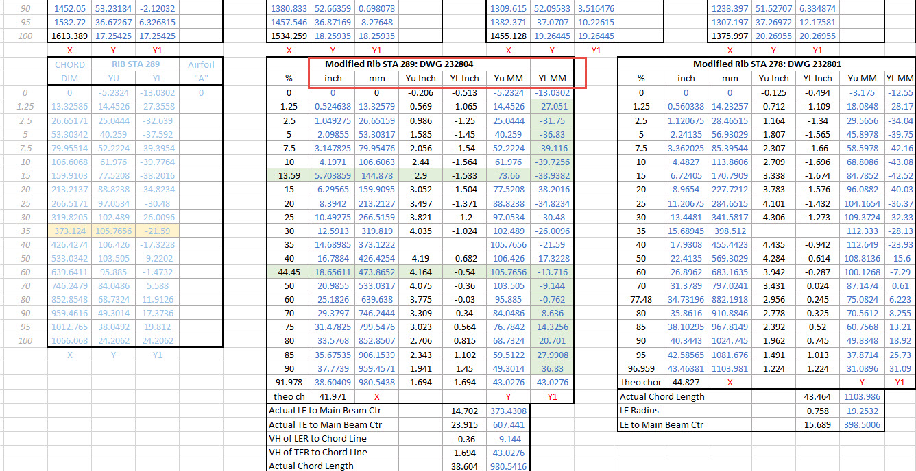
The rib profile at 1,2 and 3 was adjusted to the new coordinates for the top line only but making sure that the LE and TE were tangential to the mathematically generated curves shown in red. These end ribs are actually modified profiles according to the tabulated information on the Lockheed drawings…apparently, the profile at the wing tips is based on a NACA 4412 airfoil but when I generated a 4412 it did not match…I am not sure why but it is something that warrants further research. As I did not have the mathematical formulas or guidance on hand to check the lower profiles I accepted what information was contained in the tables…mind you I could have generated a line equation from this information in Excel. Incidentally, all the wing ribs were checked mathematically with the resulting dimensions used to generate the profiles throughout.

The first image shows a sample of the modified values at Rib station 289, highlighted in green alongside the normal profile on the left. The second image shows the explanation of how the main wing rib profiles were generated. All this information is included in the CAD/ordinate dataset. Also on the second image, you can see a typical rib profile extracted from the Lockheed drawings which shows the 0% chord is actually set back from the Leading Edge, which is most unusual. This created a few problems because now I had to determine from the CAD model the Actual Leading Edge before I could define the curved guide rails for generating the wing tip lofts.

This all may seem overkill and a lot more work than one would expect just to build a wing tip but the Inventor Loft command requires absolute precision when lofting with guide rails so it pays dividends to mathematically check everything where possible to ensure successful lofting. I shall update the CAD/Ordinate dataset over the next few days to include this new data.

.

.

.

Technote: P-39 and P-38 Updates

Technote: P-39 and P-38 Updates

An update on some recent work I have done for the P-38 Lightning and P-39 Airacobra. For the P38 Lightning, I now have the Boom Tailend interface with the Empennage and for the P-39 Airacobra, the new work includes the Auxiliary Fuel tank, Wing and underside panels at the Centre Section.

P-39 Airacobra Wing Layout and Aux Tank:

I was doing some research into the various closed penetrations on the underside panel as shown in the photograph on the right. So I modeled this panel to get a clearer idea of what was happening in this area as marked “A” in the underside view and front view images above. The 2 oblong holes are actually openings that normally would have a curved reinforcement which I understand would be used for the Auxiliary Fuel tank pipes and hoses. The Teardrops are for domed covers, which you can see more clearly in the first image view.

The Square cutout towards the rear of the panel is for the exhaust Flap and the slot to the front is for a removable panel that houses the Auxiliary Fuel tank mounting. The Aux fuel tank itself was well documented and was an interesting model to develop…I still have the fuel cap and vent pipe to add along with a few bracing struts to complete.

Following this exercise, I decided to further develop the wing layout. Although the CAD work for the wing was well-dimensioned with outlines for the Wing plan, Front Beam, Rear Beam, and Aux Rear Beam there was not much information on the actual rib profiles. We know that at STA 1 (22″) from the center of the ship the rib profile is a NACA 0015 and at the wing tip this is a NACA 23009 profile (204″ outboard). Other than that we have virtually no ordinate information for the ribs except for a partial profile at STA 7 +7.

The arrangement for the wing has been a subject of debate on several forums mainly regarding the construction of the Wing Tip. Usually, when there is a change in the rib profile the change occurs at the intersection of the wing tip and main wing however in this instance it is located at the extreme point of the wing tip. So the surface model is based on a loft between the 0015 profile at the root and the proxy 23009 profile at the extremities. This loft reveals an interesting caveat related to the evident wing twist and alignment of the Leading Edge.

Clarification on the location of the different NACA profiles was actually found in the NACA Report L-602 on the Flying Quality of the P-39 which defines the relative positions of the profiles. The caveat I was talking about relates to the wing twist…normally when we think of Wing twist or Washout we visualize the rib rotated about the 30% or 35% chord with the leading edge dropping and the trailing edge lifting slightly…but that is not what is happening here. The entire 23009 rib drops from a static position at the trailing edge towards the leading edge…the rotation is roughly 1.257 degrees. This results in a continuous leading edge downward alignment all along the length of the wing from the root to the tip.

As this is most unusual I was able to check the resulting surface model against known dimensional information for the beams and the partial profile at STA 7 +7 which matches. I still have to model the wing tip which has an interesting upward curvature.

P-38 Lightning Boom Tail End:

Another challenging aspect of the P-38 Lightning was determining the geometry for the Boom Tailend…essentially the intersection of the Boom and Empennage. We do have the lines of intersection for the Vertical Stabiliser, Horizontal Stabiliser, and the end of the boom but we don’t have any dimensional information for the curved profiles though we do have drawings that give us some idea of the profiles.

This was surprisingly difficult to get right and to be honest this final version is the result of 3 different attempts to achieve a viable solution. At first, I attempted to draw the Boom section, and stabilizers then fill the void with a surface patch to naturally define the curved fillets…with a few guidelines I managed to get a reasonable result but I incurred a few anomalies with the finished surface which I couldn’t correct. The second effort was more structured with a number of contours traced from the available drawings as a reference to gauge the curvature and then try again with surface patches but this time is broken down into quadrants, top 2 sections, and bottom sections…this was better and very close but again I had a few surface deviations at the leading edges.

Finally, I decided to have a look at using variable radius fillets…although I had already tried this unsuccessfully I changed my approach slightly which gave me good results. The fillets I used initially were tangential which caused a few problems where they met particularly on the top surface…what was happening was a sharp edge developing where the fillets intersected…so that was no good. It also mattered in which order the fillets were generated.

Eventually, I figured why not try G2 fillets and see if that worked…I am always wary of using G2 fillets due to some bad experiences using them before but I was running out of ideas and I was keen to find a workable solution. I started with variable G2 fillets at “1” and “2” with several control points to control the curvature and avoid folding the surface at the leading edges. After some fine-tuning, this worked out well for the first 3 locations. The remaining fillet for the Vertical Stabiliser did not go quite so well as it was impossible for the CAD software to give me a G2 variable fillet…so this one ended up being tangential. Perhaps with a bit more tweaking, it may have achieved a G2 fillet but I had spent many hours on this and I needed to make a decision.

There is a very very slight edging but it is almost unnoticeable on the final product. The final curvature of this model matches well with the guidelines extrapolated from the drawings and I am satisfied it is a very good representation of the Boom Tail End.

I hope you find this article useful and as usual any inquiries please get in touch at hughtechnotes@gmail.com

.

.

.

Technote: P-38 Lightning Engine Cowl

Technote: P-38 Lightning Engine Cowl:

Yet another challenging aspect of the P-38 Lightning is the Engine Cowls for the P-38J and earlier variants. As before with the Coolant Rad Scoop, there are very few ordinate dimensions so this will require a similar workflow by developing what we do know to help determine what we need to know.

Part of this development includes the Shroud Air Intake Scoop which will provide some key data for determining a partial profile for the top section of the cowl.

The engine cowl above is for the P-38J, I also have another work in progress for the earlier variants. Common to both forms is the Shroud Air Intake which is the main subject of this article. As per normal practice, I tend to first develop all the sketch profiles according to the drawing information…this is not always ideal for the CAD modeling environment but it is important reference material to ensure the final model is compliant.

The sections described in the drawing show a gradual curve intersecting arcs that form the scoop…early on I determined that these will need to be separate sketches as they will be modeled separately and then combined. The first arc section is important for sweeping the scoop duct and then of course building the profiles of the leading edge, so this was actually created as a full circle. The remaining profiles are retained as arcs.

This profile is a swept feature using the centreline (1) as the guide curve making sure that the orientation is set to Fixed and not Follow Path. All the arcs are set perpendicular to each other so it is important to make sure the swept profile follows this alignment.

Another important consideration for making the leading edge a full circle path is when building the actual leading edge. I elected to build sketch profiles at each of the circle quadrants to account for the variations in the curved swept surface. The edge profile actually extends inside to form a lip which I offset from the main surface by 0.1mm… sometimes if the surfaces are coincident this causes problems with later editing.

That worked rather well and gave me a smooth curved leading edge when lofted. A quick point to note is the loft does not do circular paths so the profile at D was duplicated and selected separately to complete the full circle.

The second image above is the fillet applied to the stitched surfaces of the scoop main body and the curved plate. This is a variable filler as I wanted to control the eventual curvature around the leading edge. Regardless of how careful I was to ensure perfect tangency at the leading edge, sometimes this is not always possible and micro variations can result in a slight imperfection which prevents the edge selection continuity for applying the variable fillet.

So what I did was select the edges as separate sections within the same command which you can see at E, F, and G. To define each of the edges you first select the edge from the top panel and then adjust the variables in the panel below. By doing this within one command Inventor will adjust the finished fillet to be continuous along all 3 sections.

The final model is rather good and very accurate. The key thing is to think ahead as to how you will model these objects from the outset so it is well worth taking your time to get this right.

Update 28th Oct 2022:

Just about finished with the P-38H Engine Nacelle…just a few items to add.

Just to give you some idea of the complexity of the underlying geometry: P-38H and P-38J Overlaid…

Update 6th Nov 2022:

This is the updated version of the Left-Hand boom on the P-38H Lightning.

.

Technote: P-38 Lightning Coolant Rad.

Technote: P-38 Lightning Coolant Rad Scoop.

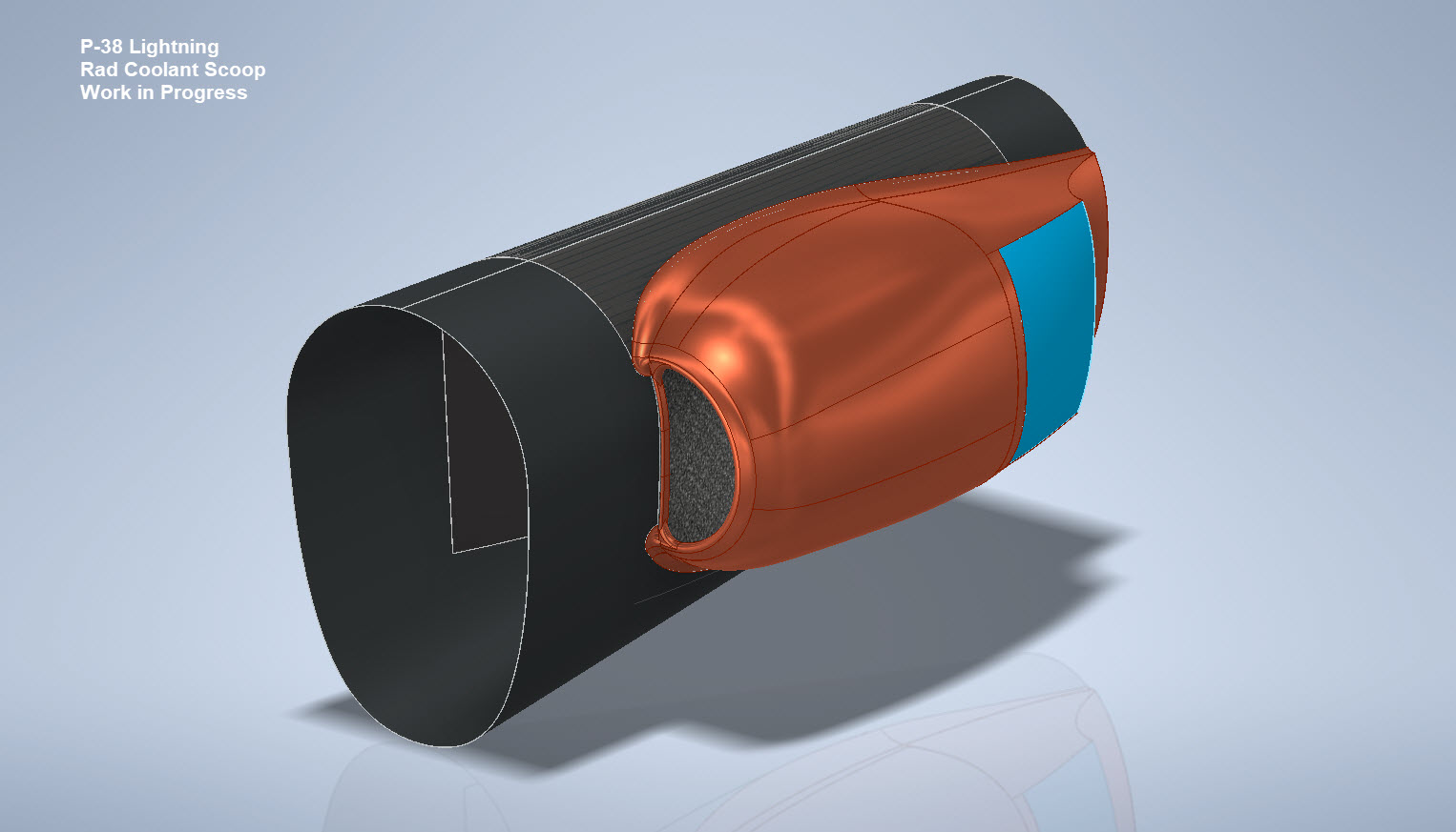
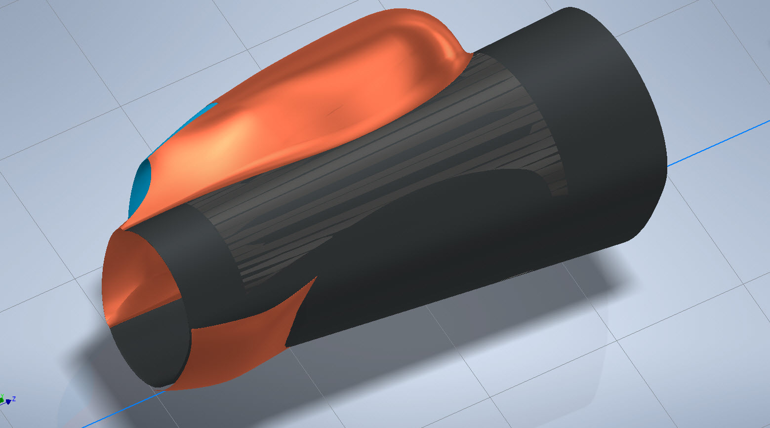
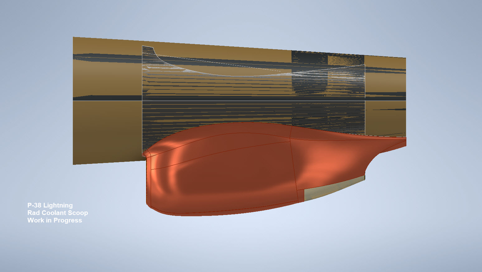
My latest endeavour is to model the Coolant Rad Scoop and later on the Engine Cowl for the P-38J. This is the Coolant Rad Scoop which was very challenging. There is not a lot of dimensional information on the drawings for this scoop which is larger and wider than the previous versions.

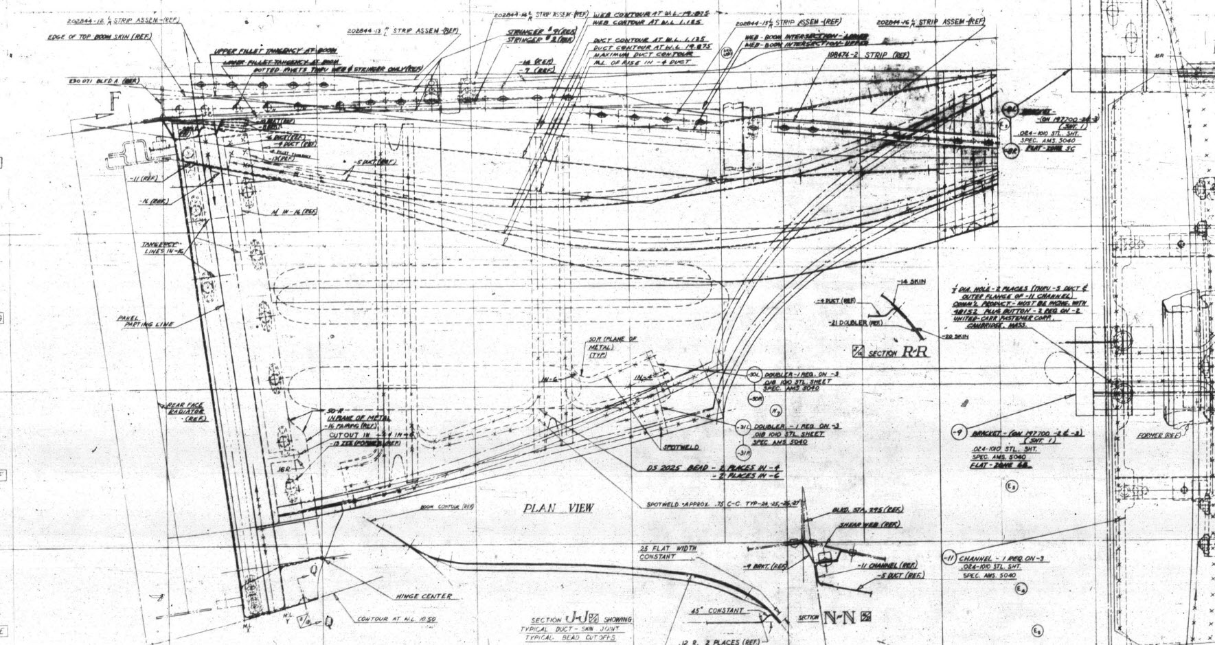
I would say this finished model is probably as close to the real thing as I can get given the complete lack of decent information. The Lockheed drawings for this scoop are largely predicated on known ordinate information which unfortunately is not available in the microfilm archives. What we do have though is a 5″ grid overlaid on the drawings…this in itself is a puzzle because what they have done is divide the drawings into 5″ square grids which may or not be relevant to end views and cross sections…so using the grid as a positional aid is inconsistent.

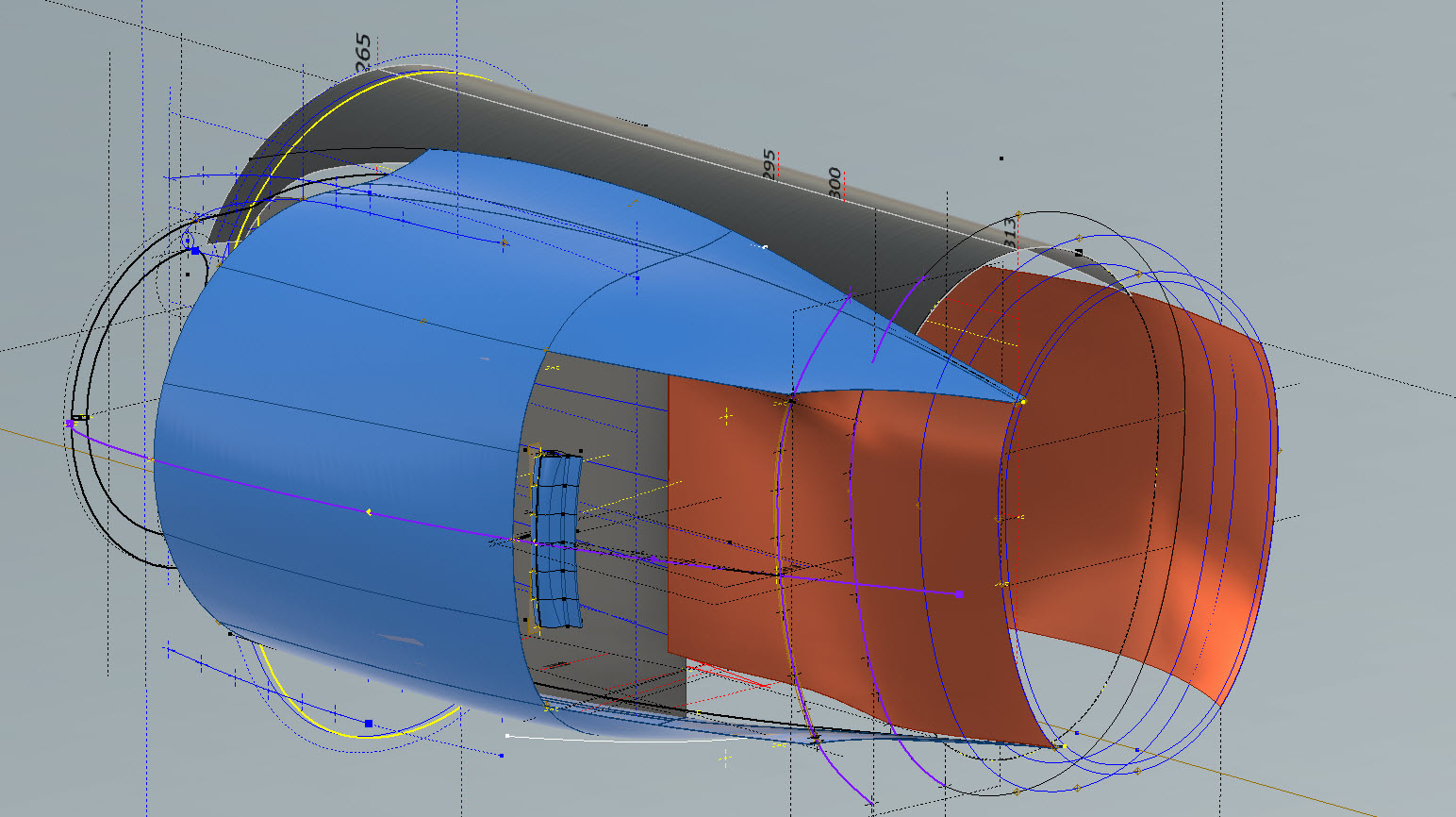
There are of course good references to the Stations which help a lot. One of the key decisions is interpreting what is an arc radius and what is a spline…I made some decisions on this early on and opted for a circular profile of the inlet and the second frame and beyond that a spline with ordinates at every 5″. It was a close match to the profiles on the drawings but if it is what the designer intended I have no idea.

Scaling digital copies of the drawings and using them as a background for building CAD models is not something I am keen on doing. I did write an article way back on scaling in X and Y directions…I shall get the link and post it here.

Fortunately, this model is being used for a CFD study so microdimensional accuracy isn’t required. The final model is what is best described as a close approximation…I don’t do close approximations…this is the exception…though I may have to undergo a similar exercise for the engine cowl!!

Inventor is probably not the best CAD product for serious surface modelling that is dependent on dimensional information. Sure they have the usual lofts, patches, sweeps and of course freeform. Freeform is a very organic feature that can work with other surface-derived types but it does not regenerate when that sketch geometry changes; a serious omission which I understand is on the Autodesk to-do list. Even the standard Loft feature is flawed.

For example, if you have 2 sketches that contain concentric profiles (like the ends of a tube) this cannot be lofted in Inventor…it just cannot be done. The other issue I have with this command is when you loft using guidelines or rails. No matter how precise your modelling there will be times this will not work…so you redo the lines over and over again…double checking everything and eventually it may work. Yet if you use the sweep command using the same profiles and rails it will work…so there are some serious issues with lofting that Autodesk really need to fix.

I think Autodesk need to take a leaf out of the Dassault workbook…I believe it was in Solidworks 2010 that Dassault decided to revise all the commands and features within the product…resolving glitches, adding functionality to existing functions and generally cleaning up the product. The main fear of the media at that time was whether there was enough to tempt users to upgrade…that was a stupid concern if a product is better and everything works as it should of course that is an absolute no-brainer, folks will upgrade and they did.

Even though Inventor has a number of glitches, I quite like the product and it is generally rather good but I do think it could be a lot better. When something does not work as it should then you can spend hours just developing workarounds to achieve the end result…time for a product cleanup.

I actually prefer Solidworks but Dassault does themselves no favours when it comes to product accessibility. You can’t just download a 30-day evaluation copy whereas Autodesk has a better approach with accessibility to their products. In fact, to get a 30-day evaluation of Solidworks you have to sit through a meeting with their sales rep and only then will they load it onto your computer for you…this is a real pain that you can’t just go online and download a copy. They do have an online access portal but for folks like me, that is not convenient. I don’t have time for sales reps, all I would want to do is buy online and download without the sales crap…you can buy Autodesk products online but not Dassault.

Getting back on the subject, what I wanted to mention is surface modelling. Generally, there are a few conditions for generating surfaces with Direction, Tangency or G2. If you are lofting or creating a sweep from a sketch you won’t have the latter 2 options but if you use a surface edge as a base for a loft you will get Tangent or G2 options. I like the option of G2 but comes with restrictions…it can cause problems with applying fillets (particular variable fillets) and surface offsets..so if you plan to do these late on in the model development stick to tangency. Variable fillets will not give you continuity with G2 surfaces.

When using guidelines or rails to control the curvature of a surface loft please consider using them judiciously. As I mentioned in the previous article overuse of constraining elements can create problems with the eventual surface generated. In the first image above I have several guidelines drawn but only a few have been selected…this gives you options so that can pick and choose between the various guidelines to see how the eventual surface evolves so it is worthwhile spending the extra time having these available…it does help.

When you do run into problems with surface modelling using Lofts or Sweeps occasionally it helps if you delete that surface and replace it with a Fill Patch…the reason for this is that you have more control over each edge of a surface patch that you would not otherwise have with those features.

The Scoop actually turned out quite well…it was a frustrating journey to get to this point but it is worth it.

Update 20th Oct 2022:

I decided that it would be prudent to also develop the earlier variant Coolant Rad Scoop for the P-38 D, G, and H models.

.

.

.