P-39, FM2, P-47, P-51 Updates

P-39, FM2, P-47, P-51 Updates:

Blimey I can’t believe I haven’t posted any updates since April…so I thought I should post an update as a lot is happening. The P-39 Restoration has been a particular focus of attention these last few months, with a particular emphasis on the Cabin rebuild.

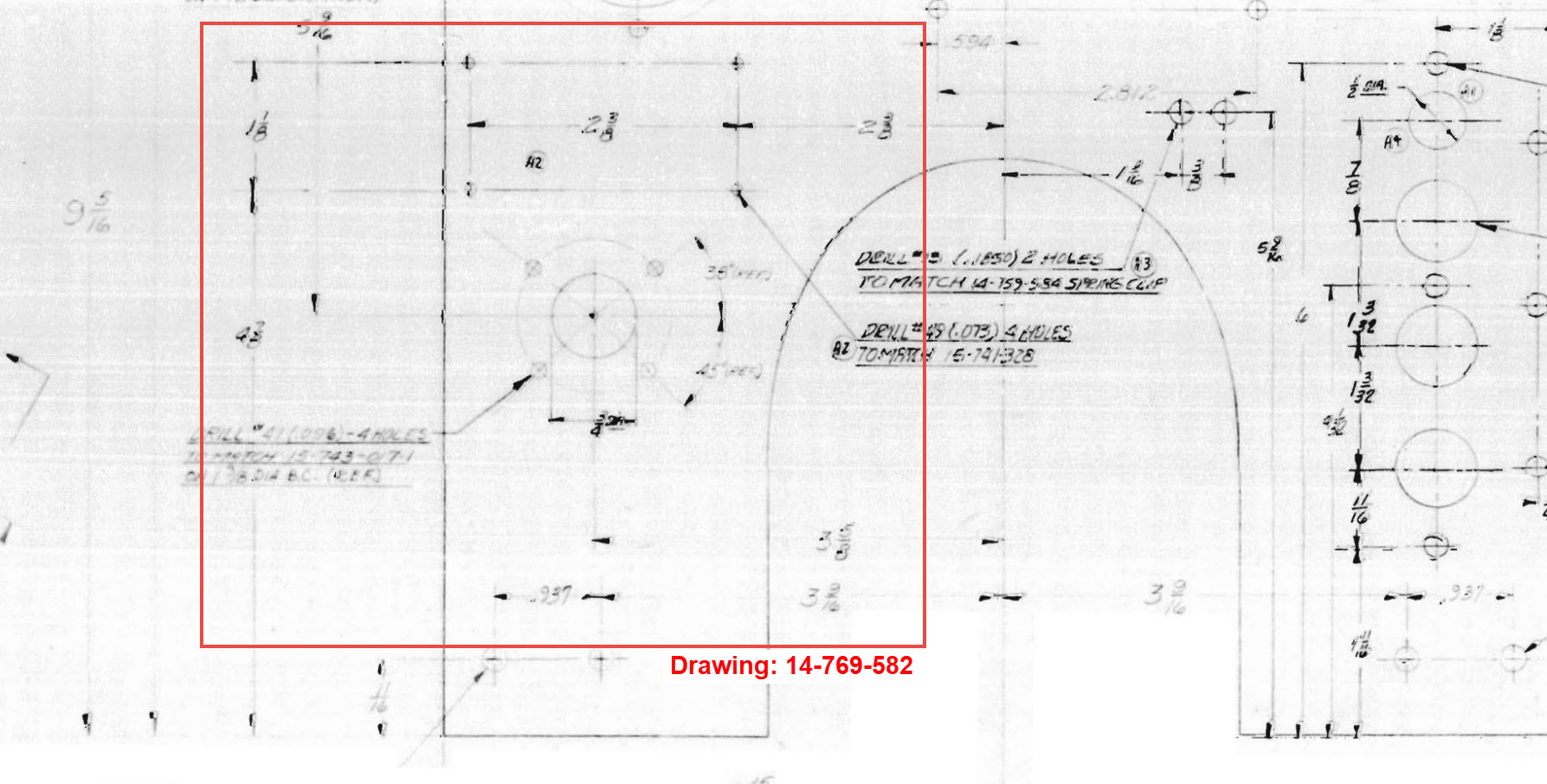
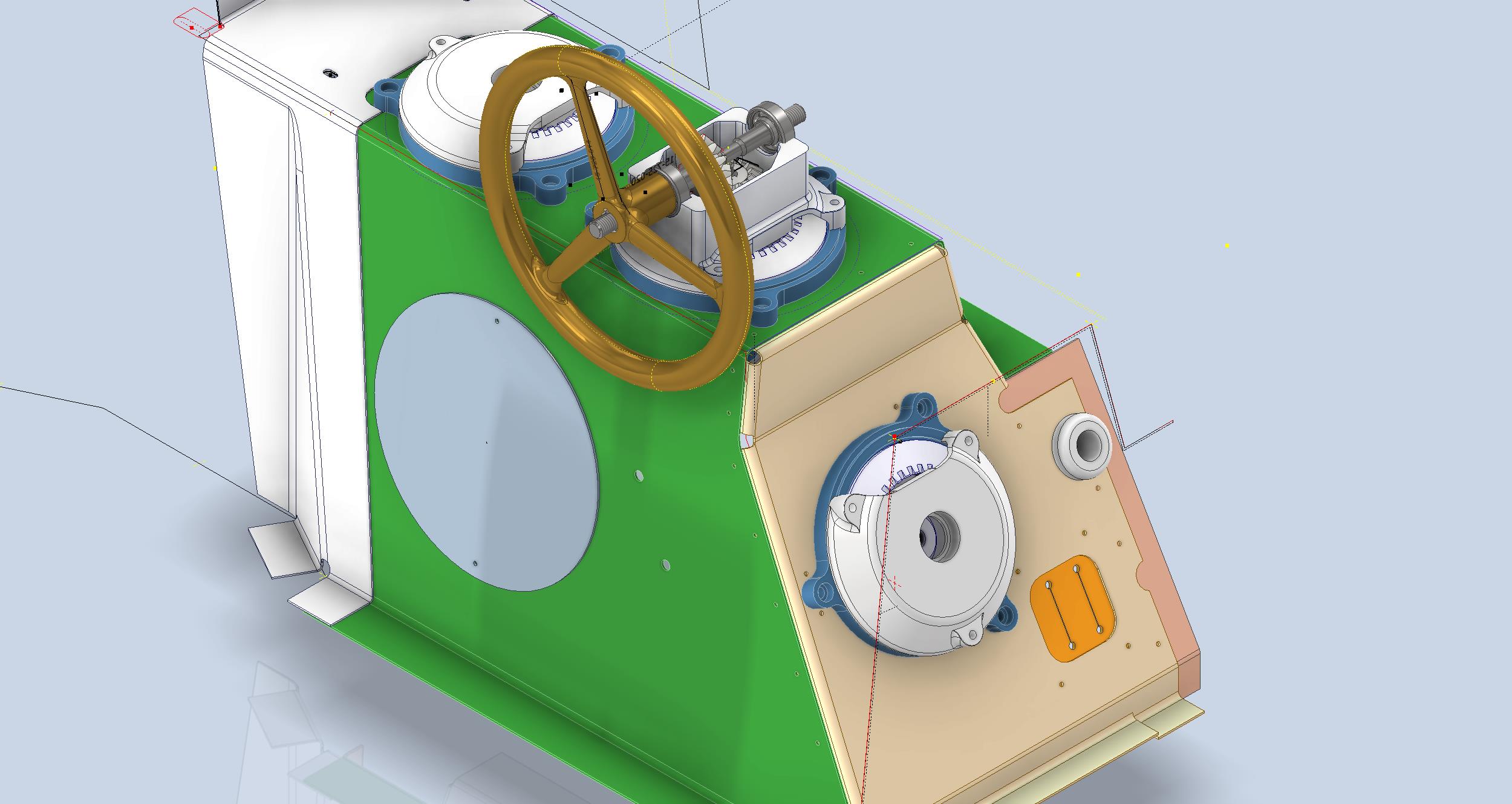
P-39 Access Door Sta 86:

P-39N-5 cannon Access Door at Sta 86 positioned between the Rudder Pedal footwells. This took a while to create in CAD due to the complexity of the rudder footwells which are only required for positional reference.

The Footwells do exist which means we have a baseline to check the dimensions in-situ before fabrication. All the original CAD 3D models are provided to the restoration shop along with fully dimensioned 2D drawings.

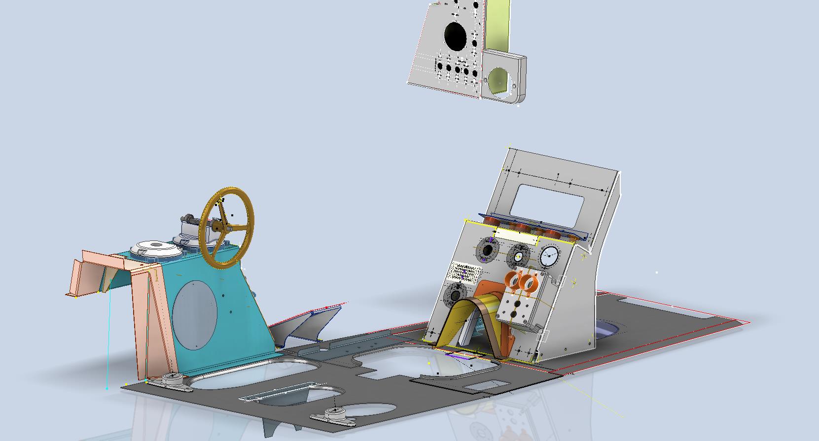
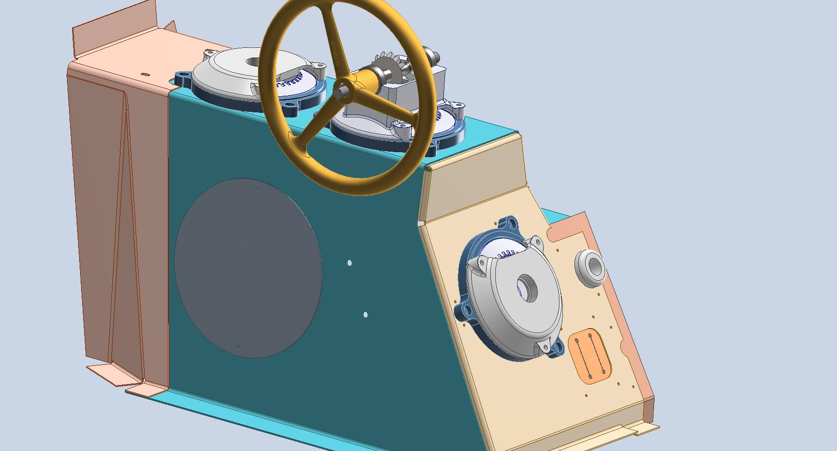
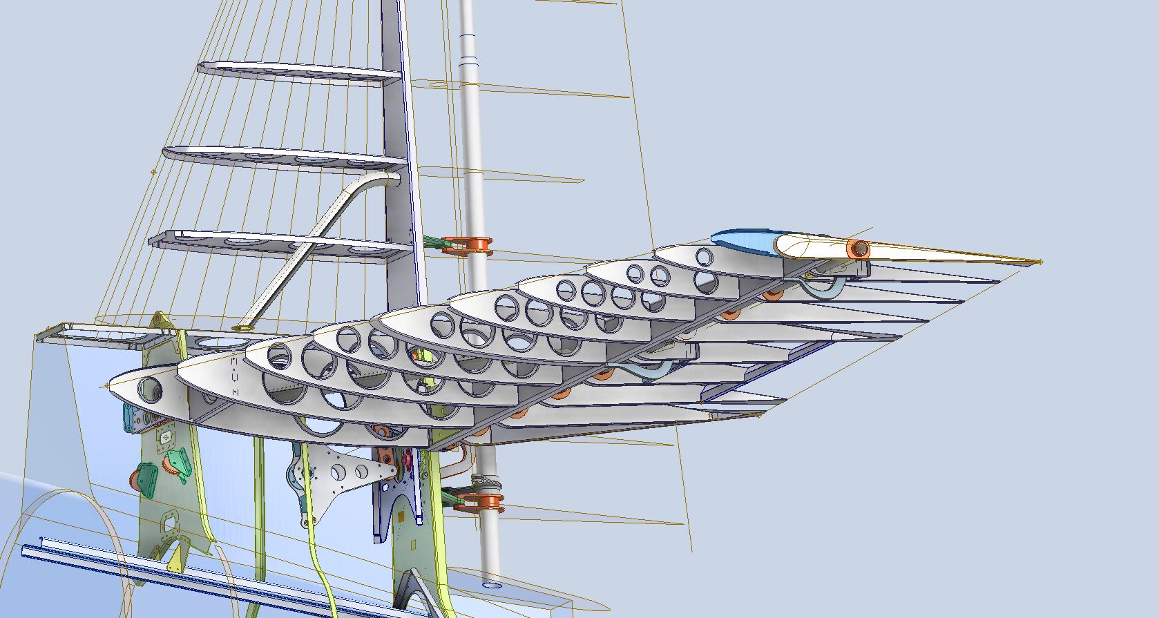
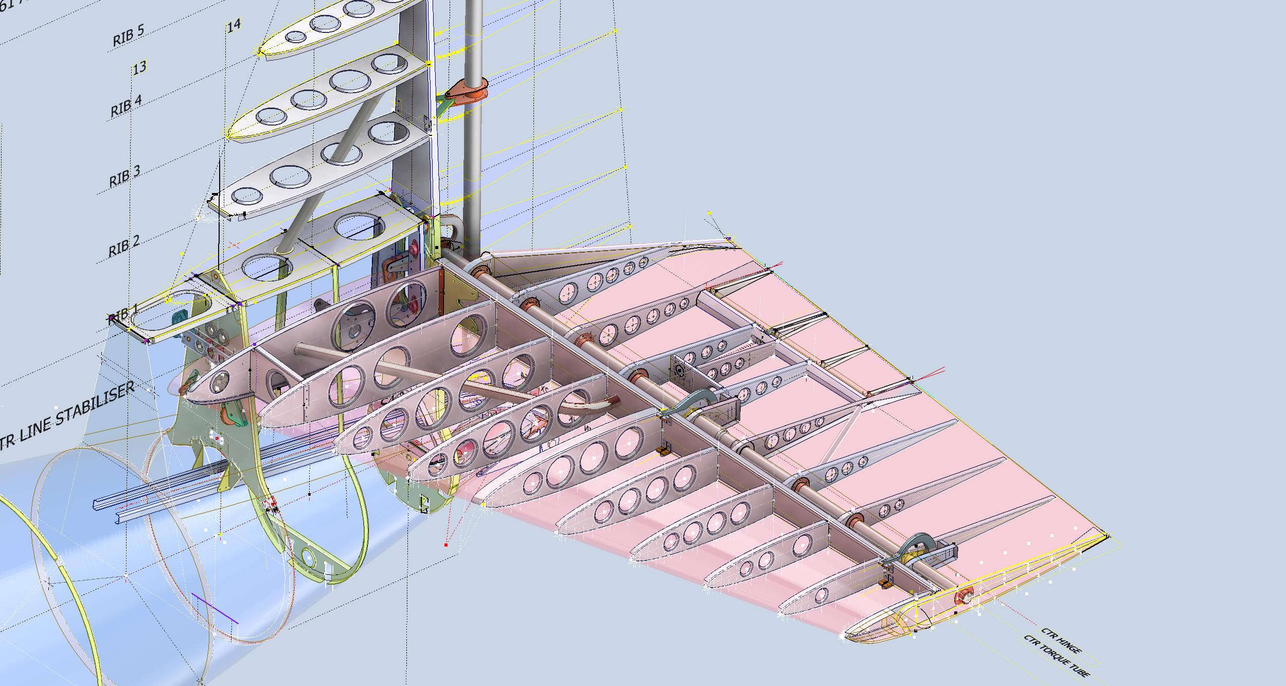
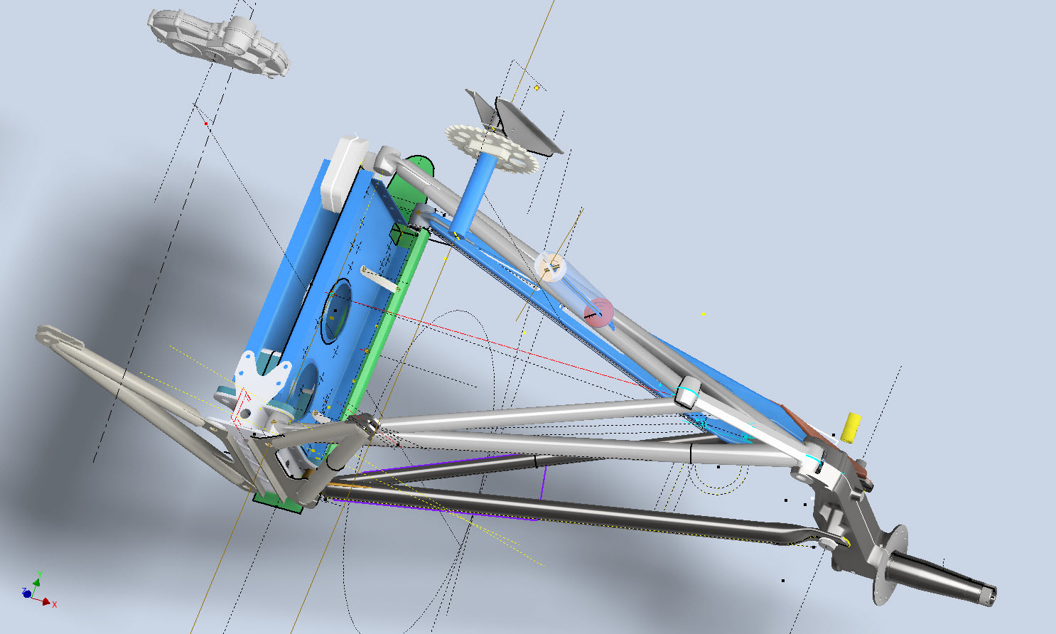
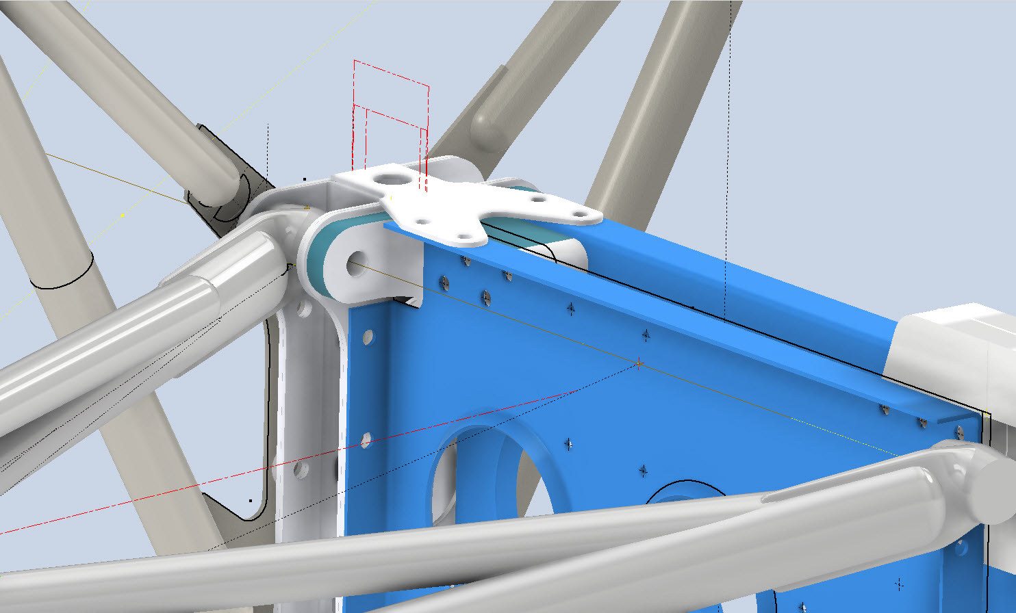
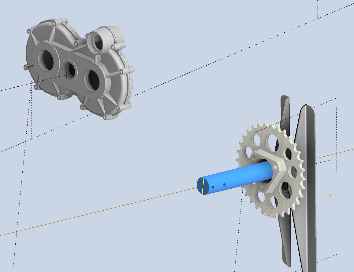
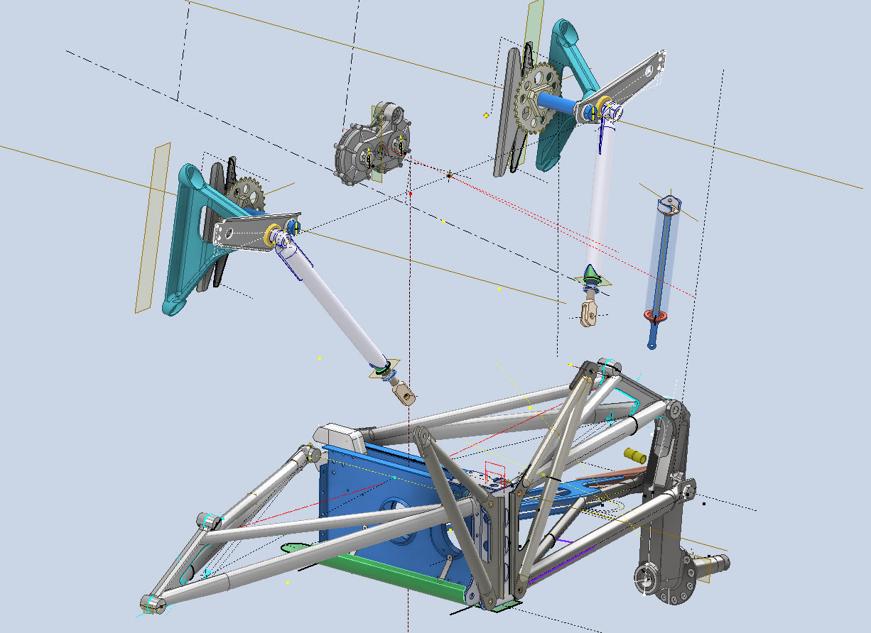
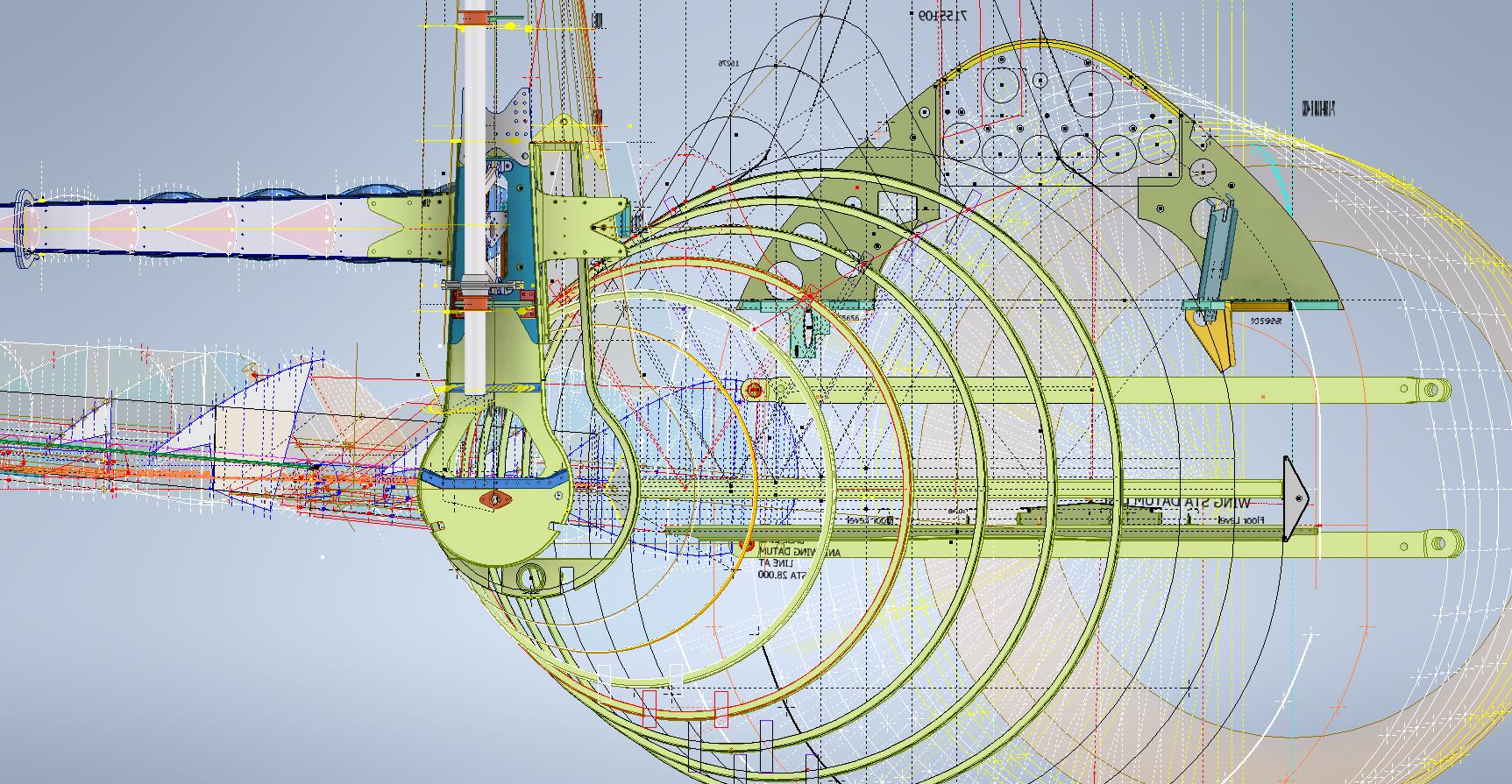
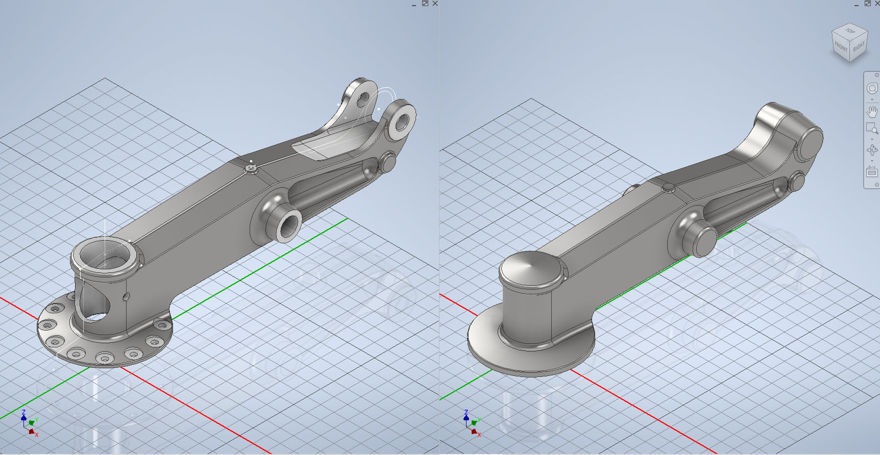
P-39 Drive Shaft Cover:

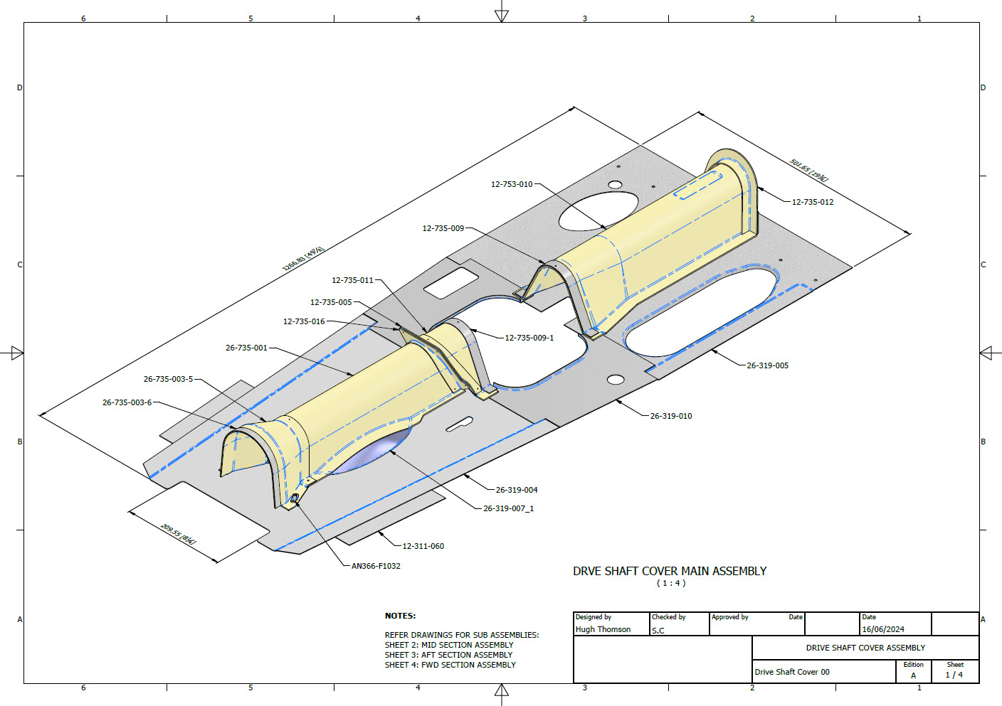
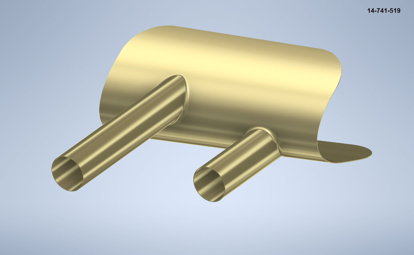
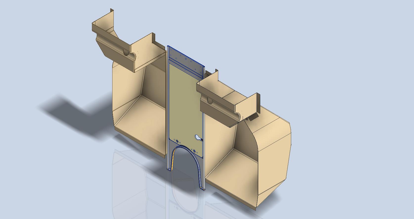
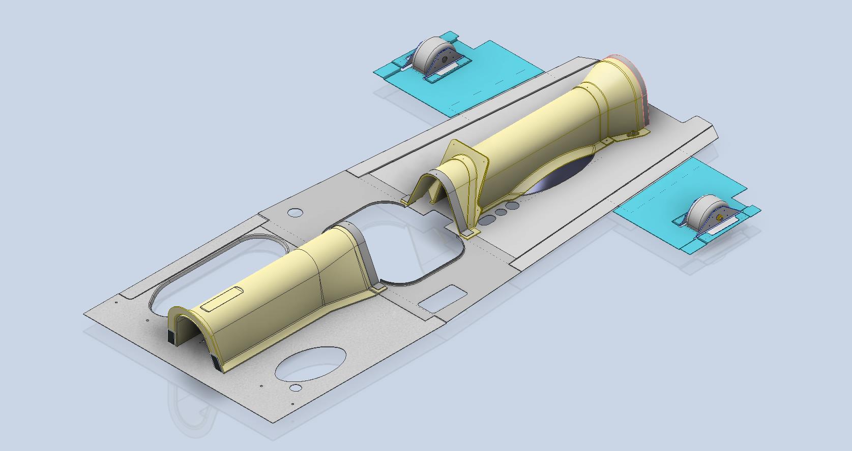
P-39N-5 Drive Shaft Cover was another interesting assembly because it was decided at the eleventh hour to 3D print the main sections. For this to work the material thickness has to increase to 0.1″ which meant that careful consideration was required to ensure that this change did not impact the interfaces with the existing bulkheads and the Radio Console.

The above images are courtesy of Omnica Corporation.

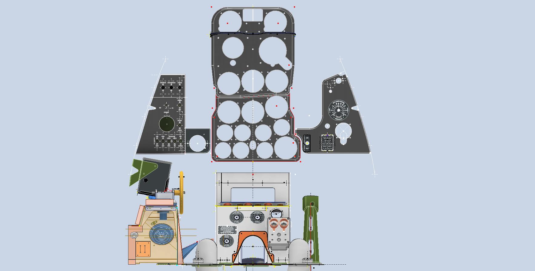
P-39 Forward Floor panels and Rudder Quadrant Covers.

As you can see the right-hand floor panel is missing and of course the relevant Rudder Quadrant Cover. The left side panel was also created in CAD because there was consideration for replacing the existing panel and Rudder Cover on that side due to the poor condition.

FM2 and P-47:

Moving on from the P-39 the FM2 project is currently on hold as my intent is to visit a few collections in the UK later this year to do further research, particularly the wing geometry. The P-47 has made its very first mention on this blog…another ordinate study for a friend which is progressing reasonably well but with the focus on the P-39 this will take a bit longer than I had planned.
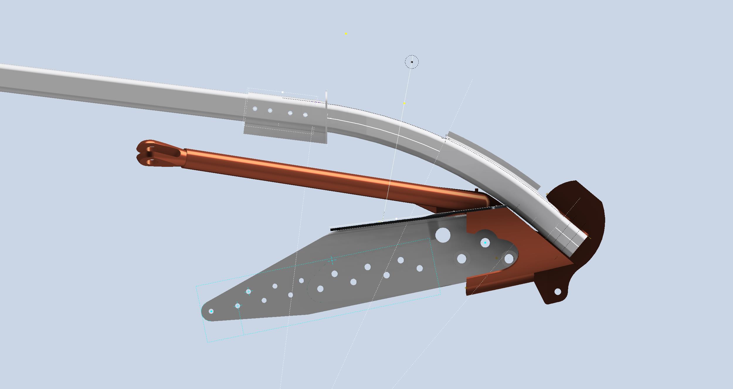
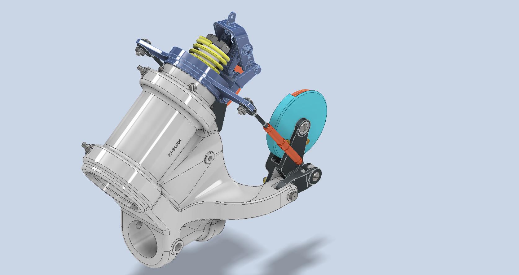
P-51 Mustang:

The P-51 has popped up again after so many years…not an update per se but a new direction for me on the 3D printing side of things. As some of you already know I have been messing around with 3D printing for a while now mainly the SLA resin. Many moons ago I fully modelled in CAD the Tailwheel mechanism, some of which I had already 3D printed. The reason for revisiting this project is to 3D print more of the parts as a test bed for different resins to examine various structural properties, dimensional accuracy and of course, play about with different finishes. Also to determine just how thin I can go with 3D printed parts and still have a workable mechanism.

This P-51 is a side project that will help me devise solutions for the ultimate goal which is to replicate flight instruments and controls.

As you know original instruments for these aircraft can be very expensive and just furnishing a static display restoration project with the original instruments somehow seems a waste when a replica would be sufficient. This way we can make available the original instruments or parts thereof for refurbishing/restoring for an actual flying aircraft restoration.

My budget for this is rather limited for purchasing materials and I also have limitations on the Elegoo Mars Pro print volume. However, I can work within these limitations…it just takes a bit longer! Something like the newer Elegoo Saturn Ultra would be a dream for this sort of stuff…maybe someday!

The resin I’m currently reviewing is the Anycubic ABS-Like washable resin which surprisingly is rather good…now I have the settings dialled in the detail and dimensional accuracy is exceptional. I will endeavour to test some of the engineering resins like the JAMG HE products though they do require a heated VAT. I see a lot of potential for 3D printing parts in the restoration of static aircraft projects. I would suggest organising the CAD workflow so the original parts are modelled to the manufacturer’s exact dimensions and adjustments made only to derived parts thus retaining the original details.

Link to AnyCubic ABS-Like Water Washable resin: https://store.anycubic.com/products/abs-like-resin-v2?variant=43608219484322

Another aspect of 3D printing worth exploring is for making molds and something else I am keen to try is whether it is strong enough for vacuum-forming thin sheet aluminium.

A lot is going on here at the moment with work continuing on the various aircraft whether that be ordinate studies, designing for manufacture or indeed exploring the vagaries of 3D printing.

P-39 Airacobra Restoration Update

P-39 Airacobra Restoration Update:

The FM2 project has been parked for a while as we must focus on the P-39 Airacobra Restoration project. The work has shifted to the Cockpit where we will literally be building a new cockpit from scratch. This is a lot more work than we initially envisaged, but ensuring we get this right is necessary.

Let me take you through some of the work involved in this process and what I did to circumvent areas where little or no information was available.

So far we have the Trim Tab Control, the Switch Box and the Centre Radio Console. The Switch Box and the Trim Tab Control have already been fabricated and test-fitted. It is very important to check the fabrication before the final installation as there is likely to be some variation in the actual versus the perceived location of structural elements. Normally I also provide additional templates to help with this process.

The Radio Console is one area where I had to do a lot of research and development work due to the lack of specific Bell drawings for the main panel. Trying to layout a panel correctly can be quite difficult when the panel drawing is not available so you have to innovate solutions from known information for the P-39C, C, D and F variants. I forgot to mention this restoration project is for the P-39N.

The process involves reviewing all existing resources including blueprints and manuals for all the other variants and extrapolating useful information to establish a viable layout for our P-39N. The first image above is a partial view from Drawing 12-769-011 (P-39C, D, F) which shows the location of the Radio Switch box, the same as required for the P-39N. The Switch box itself is a supplier component for which we don’t have the specific dimensions however, we do have the Name Plate which was used to determine the actual box dimensions. The second image is the location of the Bomb Release from Drawing 14-769-582 (P-39D-2) similar to the requirements for our P-39N. The third image is the 37mm Gun Charger and Loader.

Often when there are updates and changes to instrumentation panels it is common to reuse existing references where possible to simplify change. In the case of the Gun Loader Charger, the centre-to-centre distance of these controls is paramount as defined in Drawing 15-769-017 (P-39D) and replicated in later versions. Collectively we now have pertinent information that in combination will give us the information needed to lay out that actual panel for the P-39N. Still, some finishing work to do on this and I am satisfied this is a good solution.

You will notice that I have modelled in the floor plates which was necessary to help check instrument locations. Sometimes you may have to actually model the cable routings, floor penetrations and the power conduits to check termination locations which in turn checks instrument positions. Fortunately for this restoration, the majority of the floor plates are reusable except for the Aft plate which will need to be replaced…a temporary plate is currently installed for safety reasons.

Often with a little bit of research most problems where drawings are not available or in some cases illegible can be overcome and it helps to have some background knowledge of how the design process actually works and how key information is retained throughout the development of new variants.

In most cases, research is the key to achieving solutions; take time to review existing materials and not just drawings but also manuals and occasionally correspondence to find relative data that will assist with your goals. Often engineers will trace outlines and profiles from scanned blueprints which in my opinion is not good practice when a little research and time will achieve more accurate and professional results.

Update 10th May 2024:

A few images that show the latest update for the P-39N Cabin model.

F4F/FM2 Wildcat Project Model 02

F4F/FM2 Wildcat Project Model 02:

Project Update: Empennage: Dimensional accuracy to 1/64″:

  • Horizontal Stabiliser 95% Complete
  • Elevator 90% Complete
  • Vertical Stabiliser/Fin: 90% Complete
  • Rudder: 75% Complete
  • Fuselage Stations 15 and 15A: 100% Complete.

Project Sponsor Content Only.

For all inquiries drop me a line at hughtechnotes@gmail.com

F4F/FM2 Wildcat Project Model 01

F4F/FM2 Wildcat Project Model 01

The first of the F4F/FM2 Project models will be ready from the 1st of March 2024. This is the first in a series of accurate CAD models for the F4F/FM2 Horizontal Stabiliser and Elevator. These models will only be available to project sponsors. Download links will be emailed to the sponsors on 1st March 2024.

These images show the work in progress. I still have the Elevator Trim Tab, Trailing Edge and the lightening holes to add.

The red profiles at the ends of the Elevator are the skin end caps…all models will include skin profiles for reference. The single rib shown in blue is still to be dimensionally verified.

As usual all inquiries to hughtechnotes@gmail.com.

Update: 4th March 2024:

The horizontal Stabiliser and Elevator model is now done as far as is possible from current known information. As we don’t yet have details for the actuator this is not included…further research will hopefully provide more information.

F4F/FM2 Wildcat Project Update

F4F/FM2 Wildcat Project Update

I thought I might share some images on the progress of the F4F/FM2 project.

Arresting Gear Assembly:

This is surprisingly complex partly due to the poor quality of the blueprint archives, but also the fact that the key setting out information is fragmented and spread out over several resources; drawings and manuals.

I plan to document everything I have learned about this area and develop a single drawing showing all the key dimensions and datums for establishing the association between all the different components, fuselage bulkheads, and profiles for the skin surfaces.

Fuselage Updates:

Alongside the above, I have also been working on some updates to the fuselage bulkheads at Stations, 14, 15, and 15A. On the forward section of the fuselage, there are some minor updates at Stations 2 and 3 and a fully modeled bulkhead at Station 6.

I haven’t seen much daylight in this past week, literally working day and night on this project. Nothing is taken for granted nor assumed so a lot of time is spent on cross-referencing data and sourcing additional information. The project is moving forward quite well but I really need to take a few days off away from this computer so it may be a few weeks until my next update.

F4F/FM2 & P-39 Updates

F4F/FM2 & P-39 Updates:

January has been a busy month with updates to both the F4F/FM2 and P-39 projects. The former CAD project now includes bulkheads at Stations 3 and 4 as well as ongoing work with the Landing Gear, Engine Mounts, Station 2 bulkhead, and Station 5.

The P-39 project focus is now on the Cockpit arrangements starting with the Trim Tab Control Unit located adjacent to the pilot seat. The initial requirement is for the sheet metal work which is now complete and fully detailed with flat patterns. The dials you see are for a future requirement that may be 3d printed. I have also calculated the geometry for the gears and pinions if we need to manufacture new parts…this has all been tabulated in a separate drawing.

As mentioned previously these models will only be available to sponsors. The basic CAD/Ordinate datasets though are still available as listed on the CAD Resource page.

If you would like to sponsor either of these project builds then please get in touch at hughtechnotes@gmail.com

The F4F/FM2 project will be an accurate full structural 3D CAD reference model and likely will be ongoing for most of this year. The P-39 CAD project is dictated by the current restoration at Planes of Fame and is fully detailed for manufacturing purposes.

F4F/FM2 Wildcat Landing Gear Update

F4F/FM2 Wildcat Landing Gear Update:

I have been busy with the Landing Gear CAD model for the F4F/FM2 Landing Gear assembly.

These images give you some idea of the progress to date. This is quite a challenging project due in part to the poor quality of a few drawings but also to the ongoing checking of dimensional relationships between the parts. Most notable is the forward Drag Link Support where you can see several red lines which is a visual indication of stated minimum and maximum tolerances. Also on this part, it is worth noting that the top pair of main holes are at 4.0625″ x/centres whereas the lower pair is at 4.1557″ x/centres…a minor variation but obviously critical dimensions.

The roller chain sprocket is a calculated profile to suit the specified roller chain; there is a smaller sprocket yet to be added to the Retracting Mechanism gearbox. This part of the project will take a while to complete and it will eventually also include the Engine mounting frame.

My Project Plans For 2024

My Project Plans For 2024:

The primary project for 2024 will be the F4F/FM2 Wildcat development. I aim to have a highly detailed structural model at either 1:10 or 1:15 scale 3D printed by the end of the year. Due to the requisite accuracies, this will be MSLA resin printed. My work is simply to produce the most dimensionally accurate aviation models in 3D CAD and accordingly fully documented.

I have recently started building the Landing Gear for the F4F which is shown below; this is the axle part # SP597. The image on the right is the forged model which is derived for machining into the part on the left.

Another example is again the Landing Gear; this time the Lower Drag mechanism. Through exhaustive research, I can go from an almost illegible blueprint to a clear sketch on the right. This is why I do what I do.

The other aircraft I will be revisiting is the P-38 Lightning as some aspects of that project warrant further research. For both aircraft, I will be visiting the collections at RAF Cosford and Shuttleworth later this year to hopefully fill in some of the blanks.

The projects will also involve updating my blueprint archives to make it easier to search for drawings initially by renumbering all 8000 plus drawings inclusive of drawing numbers. I have already started this for the F4F Wildcat which was helped enormously by some clever folks on YouTube. https://youtu.be/I9ffWZ_Bt6o?si=OEog79e-XaRUZz7K

The first portion of the numbering sequence is the original scan reference followed by the actual drawing number. The An Parts library will also be updated with additional conversions for use in other CAD systems.

2024 will no doubt be a busy year for me with the 1:10 scale printed model being the biggest challenge.

I hope that you will continue to support my endeavors throughout this year. Happy New Year.

P-39 Restoration Project: CAD Services

P-39 Restoration Project: CAD Services

12 months ago I started providing CAD design services to Planes of Fame, Chino to assist them with the restoration of a P-39 Airacobra. This aircraft is a static display restoration so we had some latitude in the manufacturing of the various parts. This included 3d printing (which is done by a professional company), sheet metal work, and vacuum forming.

The CAD models generally are for small complex geometry parts as you can see in the examples posted below. When preparing these models everything is double-checked against blueprints and where necessary the aircraft itself to ensure correct profiles.

I have over 40 years of experience in Engineering Design and drafting; in fact, I actually started my career as a draughtsman on the drawing board. I question everything and take nothing for granted with a focus on detail and accuracy. So when I prepare the 3D CAD models I also create a 2D dimension drawing as a checking mechanism to ensure accuracy and also as a reference for the engineers. If the 2D drawing is actually produced specifically for manufacture instead of being a design check it will incorporate all required standards references, tolerances, and material specifications.

3D CAD modeling of parts for aircraft can be quite complex and can take a long time to complete. The smallest part here would normally take about 3 hours. That may seem a lot of time for small parts that appear to be quite straightforward but often it is the reference geometry not visible that takes the time, whether that be the curvature of the wings or fuselage. Then everything is checked and documented.

The P-39 Restoration project still has a long way to go which I feel privileged to be part of.

If you require parts developed in 3D CAD for your project then please don’t hesitate to drop me a line at hughtechnotes@gmail.com.

I would like to take this opportunity to wish everyone a Happy New Year.

F4F/FM2 Wildcat Progress Update

F4F/FM2 Wildcat Progress Update

The ordinate dimensional study for the f4F/FM2 Wildcat will now be ready in January. This will include dimensional information for all the rib, strut, and frame profiles fully documented in 3D CAD, 2D drawings, and Excel spreadsheets. Probably the most accurate dimensional study available.

In January I will be taking this project and the P-39 Airacobra to the next level. The plan is to fully 3D model in CAD all the primary structural components for the wings, flaps, ailerons, elevators, rudder, fuselage, empennage, cowl, and landing gear; and then produce a 3D printed scale model at either 1:15 or 1:10 scale. The F4F empennage is already partially fully 3D modeled in CAD which gets us off to a good start in the New Year.

These models will be printed on an Elegoo Saturn MSLA printer capable of producing a 0.02mm accuracy. The resin I will use will likely be PLA with a 10% mix flex resin to minimize brittleness. This is an ambitious project and will take most of the year to complete.

Many of the components are thin-walled profiles which may have to be adjusted to suit the scale of the printed model. Some testing will be done to find the minimum thickness to achieve model integrity and maintain dimensional accuracy.

This project is something I have been thinking about for a long time which is only now possible with the incredible accuracy achievable by the latest 3D printing technology. The final 3D CAD model; suitable for 3D printing; will NOT be available publicly but I am open to the idea of private sponsors.

As usual, all inquiries to hughtechnotes@gmail.com