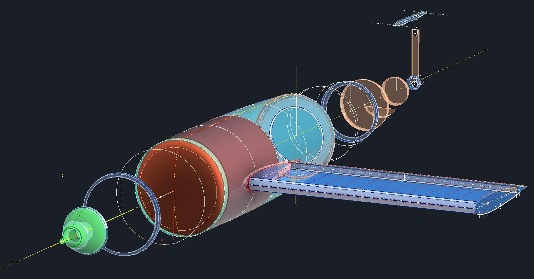
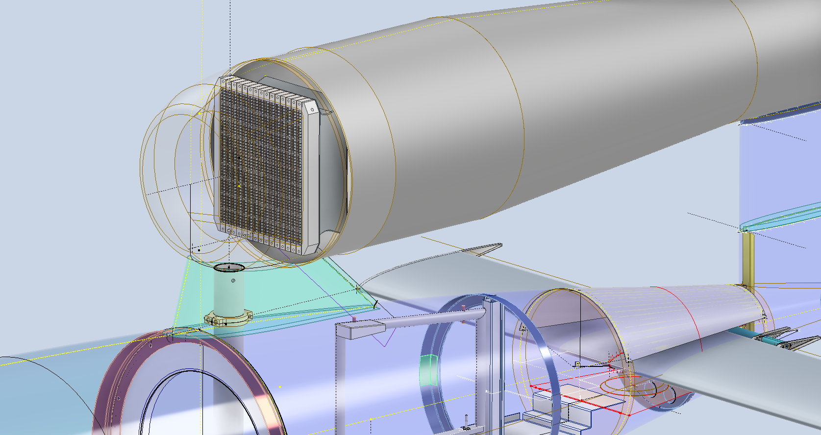
The JB2 project is progressing quite well, with most of the structural elements in place. I will be doing a lot more detail work on the surface skin and, of course, adding the main support elements for the engine structure. In the interim, I thought it may be prudent to post a few images of the project for your perusal.
Comments or inquiries as usual to hughtechnotes@gmail.com.
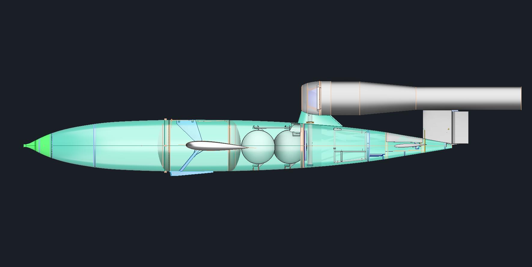
The Republic-Ford JB-2, also known as the Thunderbug, KGW and LTV-N-2 Loon, was an American copy of the German V-1 flying bomb.
I came across some blueprints for this and decided to develop a hyper detailed CAD model.
The blueprints are very poor quality; incidentally all of them are marked “illegible”, however, it is possible to extrapolate some key information that will provide a good accurate replica. At this stage, I am not sure exactly how far I can take this project but I shall endeavor to model every part that I can find and then take it from there.
As usual, I have all the key dimensions listed in spreadsheets for future reference. I studied the wing profiles and discovered the airfoil used is the NACA 0015. The wing construction is rather unusual in that the ribs are formed from 2 mirrored sections. As the project progresses I will explain that in more detail as an addendum to this post…so watch this space.
Update 26th Dec 2024:
Made quite good progress on this project. Still a lot of work to do, particularly on the empennage. I will take a break for a few days and post another update in a week or so.
Update 1st Jan 2025:
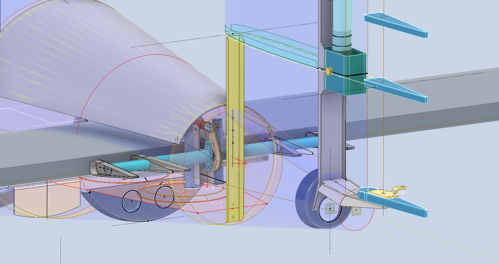
A few images showing the progress on this model build showing the Engine Intake, Wing construction and miscellaneous work on the Empennage including the Rudder Support.
Update 7th Jan 2025:
The horizontal stabiliser is almost finished. Notice the inclusion of the spoilers on the underside. The Aft fuselage deck has also been added. A close-up view of the Air bottles shows the surrounding supporting structure.
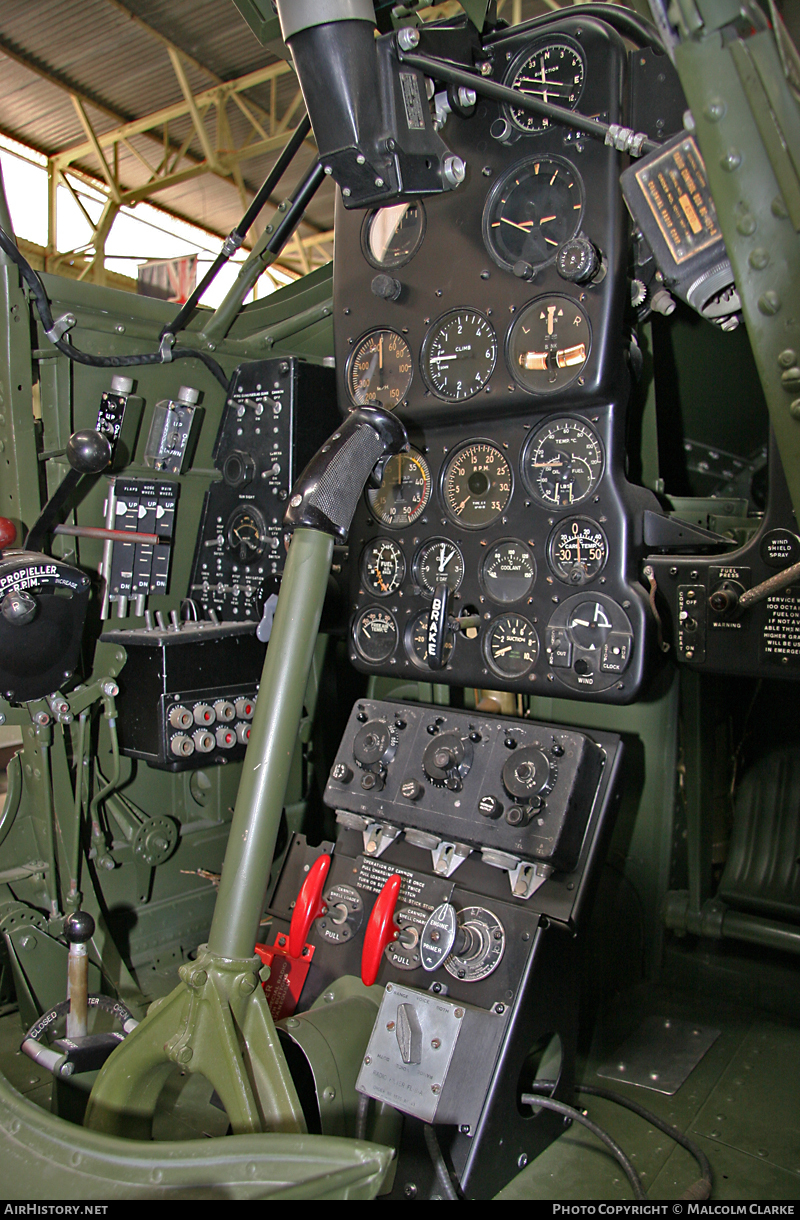
For most of this year, my primary focus has been the restoration project for the P-39 at Planes of Fame. That is still very much work in progress. At this stage, it is mainly the fabrication side of things, as the majority of controls have been drawn. The mounts for the Gunsight are currently being made. I hope to include some photographs of the installation in a later post.
The Gunsight was an extensive and challenging study…the drawing layout shown above was derived from a dozen or so blueprints and various manuals compiled together on one drawing. The circled dimensions are those verified from one or more sources.
During this time I have been doing some preliminary studies for the P-47. Over the last few weeks, the P-39 project demanded less of my time which has enabled me to further develop the ordinate study for the P-47.
The basic Layouts are developed for the Cowl, Fuselage, Empennage, Wings and Cockpit Enclosure. Still a lot of work to do on the details and resolve a number of queries.
One particular area of interest is the wings. As you can see a lot of work has been done on this layout which shows the Main Spars (shaded), Flaps and the leading and trailing edge profiles. The Aileron and Wing Tip is still a work in progress. The wing comprises 6 thickness variations of the S3 profile…15% at Sta 0 (Ctr aircraft), 14.2% at STA 74 (0.3 x Span), 12.3% at STA 123 (0.5 x Span), 10.5% at STA 172 (0.7 x Span), 9.2% at STA 222 (0.9 x Span) and 9.0% at Tip extent STA 246.
For the Main Spars we have the vertical dimensions coupled with the correct lines for the Flaps and Leading edge providing key important ordinate points that the rib airfoil profile should match. For the Airfoil ordinates I referenced documentation on the Republic S3 profile from the UIUC website and The NACA Technical Reports WRL-98 and WRL-159.
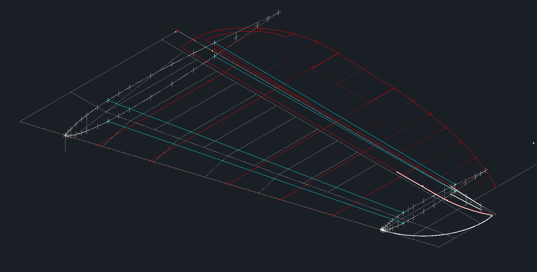
For The Horizontal Stabiliser we do have good information to develop a 2d plan layout including the dimensions for the Elevator to derive an accurate trailing edge. We lack sufficient depth information for any of the spars or ribs. Therefore, it is important to ensure we have the correct Stabiliser airfoil profiles.
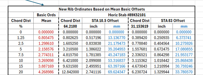
The Republic blueprints list the airfoil ordinates at station 10.5 and station 83. These were recorded on spreadsheets and subsequently onto the CAD model. I found that the alignment for the spar positions and the 70% chord were slightly out. I reverse engineered the offset ordinate data to derive a Basic profile which I intend to use to further develop the intermediate ribs.
The first table above shows the recorded ordinate data for the airfoils at Sta 10.5 and 83. Working back from the offsets you can see the Basic Ordinates are similar but not exact. Therefore it seems logical to take the mean values from both tables to derive a workable basic profile which I can use later, shown in the middle column. The second table shows the adjusted ordinates for each profile. You may be asking what recognizable profile did Republic use for the stabilizer…again I do not know for sure. I have a parametric table setup for the more common NACA profiles used for other similar aircraft and none match.
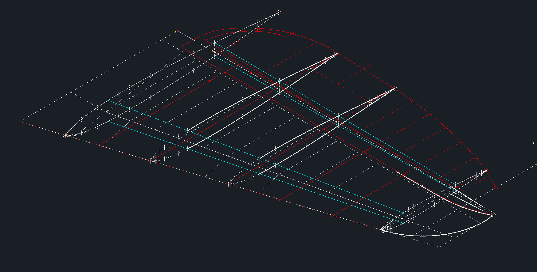
The key dimensions for the profile relate to the 70% chord offset and the alignment with the front spar center. What I think is happening is the area from the leading edge to the 70% chord defines the surface for the Horizontal stabilizer and the curved trailing edge of the Elevator is essentially morphed to this line. What few vertical dimensions we have from several areas tend to match with this arrangement.
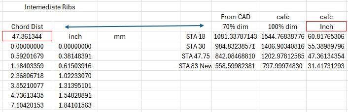
The cyan lines show the alignments at the front spar and the 70% chord for reference. The plan outline for the Elevator is drawn according to the known ordinate points. The second table above is designed to give me the airfoil offsets for any rib according to the chords derived from the CAD model…this is essentially the position of the measured 70% chord and is calculated to give me the actual chord length. All of this will be verified which means trawling through the many thousands of blueprints I have to find key offset data I can check against. Of course, I could use the Aircorps database for this but the many scans of this area are blacked out..the archive I have is much better quality.
I take nothing for granted with these studies and try to verify dimensional information from more than one source. I firmly believe that if we get the dimensional information correct everything else will fall into place.
As usual please get in touch with any technical queries or comments. hughtechnotes@gmail.com
Update 20th Dec 2024:
I have the basic geometry for the Horizontal Stabilizer and Elevator worked out…some detailed work is yet to be done on the Tip and the main Spars.
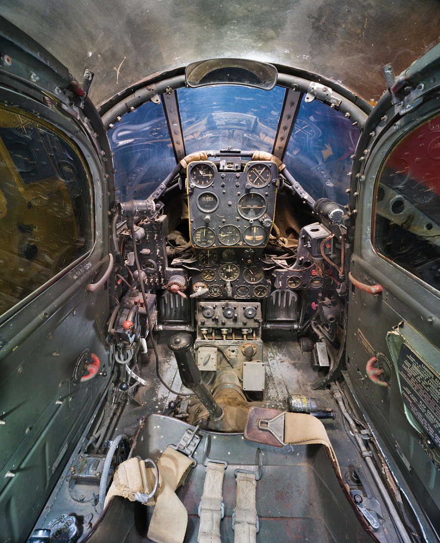
Working on the controls and instruments for the P-39 spawned a plethora of questions about how these controls actually worked. So I endeavored to incorporate the inner workings in the Trim Tab Control CAD models. This was specifically to get a better understanding of how they work. This was not a mandated requirement. The initial work scope was replicating the external components for a static display P-39 restoration.
Often enough in museums and private collections, we only see the external controls. For many, this is all they want to see. But what if we also see the internal gears, pulleys, shafts, and bearings to understand how they operate? This is exactly where I now want to go with my future projects.
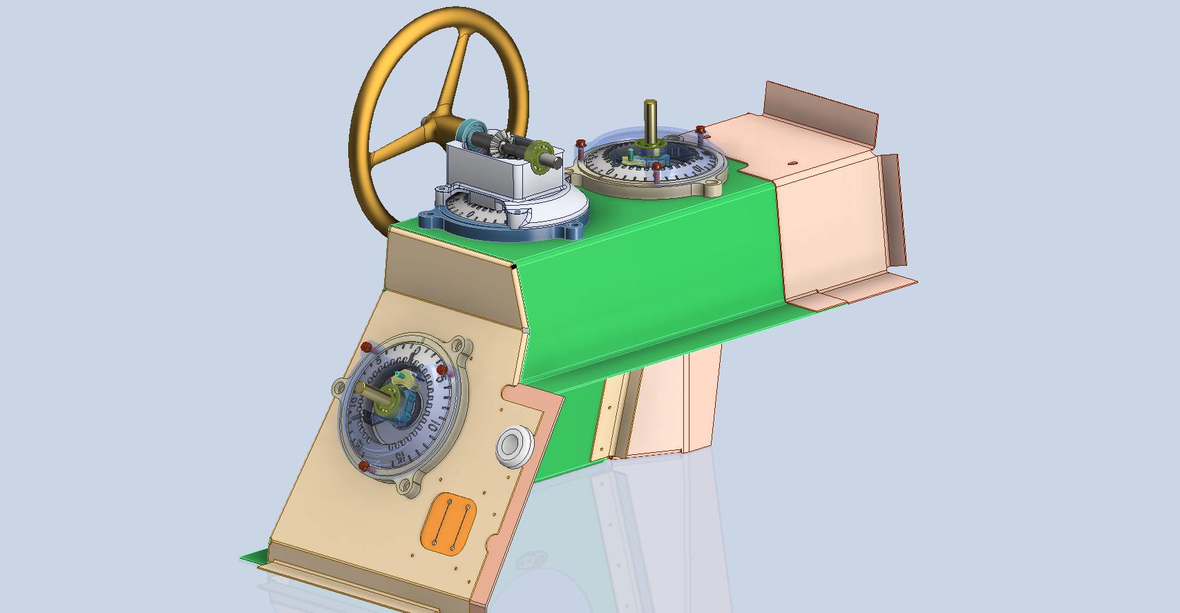
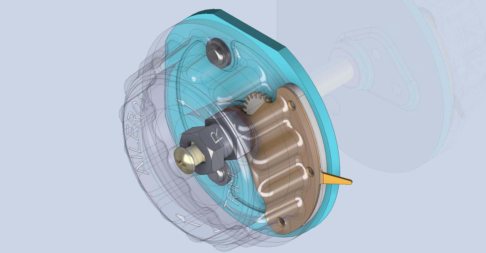
The Trim Tab controls for the Elevator, Rudder and Aileron are already modelled for the P-39 including the internal components. These dials and controls are currently being manufactured for the restoration project. The decision has now been made to incorporate the working mechanisms as functional replicas. This is great and will actually have some form of function, however, the mystery of operation still eludes the operator. I want to take this a step further and produce desktop models with Clearview casings so that the internals are visible. The exact method is still under review. It will mainly comprise 3D printing techniques for the main components attached to perspex casings.
The dials for all 3 controls are similar with the Rudder and Aileron dials operated by a control knob (not shown) and the Elevator Tab controlled by a wheel as shown. At the base of each control dial there is a sprocket for a short Roller Chain which in turn is attached to operating cables. Out of curiosity I decided to have a look at other aircraft to see how alternative mechanisms were developed for the P-51 and the FM2.
For the P-51 the Trim tab controls are comparable in their operation with the internal gearing arrangements but differ slightly in design.
The dials for the Aileron, Elevator and Rudder are all similar to the CAD model shown. The Elevator and Rudder have cable drums attached to a long shaft for direct cable operation whilst the Aileron has a chain sprocket similar to the P-39 Trim Tab controls.
The plan for the P-51 is to fully model all the components in the assembly shown, complete with cables and chains to simulate operation.
A small point of interest; the various aircraft designed by the same manufacturer often share common parts; for example the NAA drawings for the B-25 share the same Trim Tab control knobs as the P-51 and listed accordingly. For some reason, the P-51 drawings do not reciprocate.
If you can’t find drawings for a particular part, check collections for other aircraft by the same manufacturer. Occasionally, this can be worthwhile. Similarly, with Grumman, many parts were shared with the FM2 and the Grumman Goose.
The above model is the FM2 Elevator Trim tab control, the main body of which is typical for the Aileron and Rudder on Grumman drawing 13690. The Grumman Goose has similar controls shown on the Grumman Drawing 13693. Shared components across the various aircraft are listed on the Grumman FM2 drawings.
This Trim Tab control for the FM2 is probably the most complex I have studied so far…requiring very fine manufacturing tolerances. I am not entirely sure yet how this works as there is a complex array of tabbed washers that act as stops for the dial in both directions; it is unclear at this stage how they should be configured…I will get it worked out in due course.
A lot of work to do on these projects which will definitely keep me busy through 2025.
During the development cycle of any aircraft the manufacturing standards tend to evolve and commonly change content, description and name. Keeping track of those changes is key to ensuring the defined parts are correct for the assembly of components.
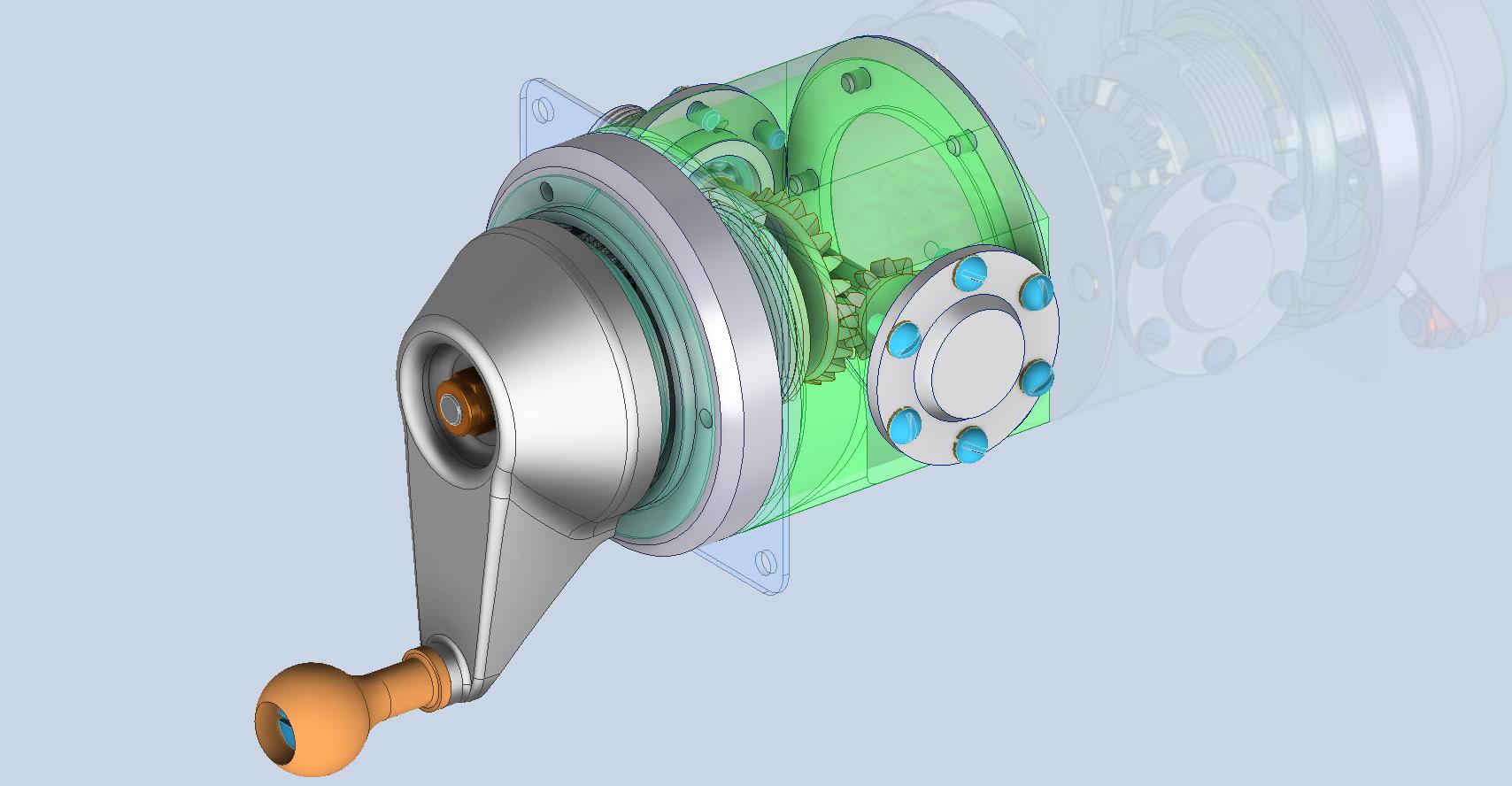
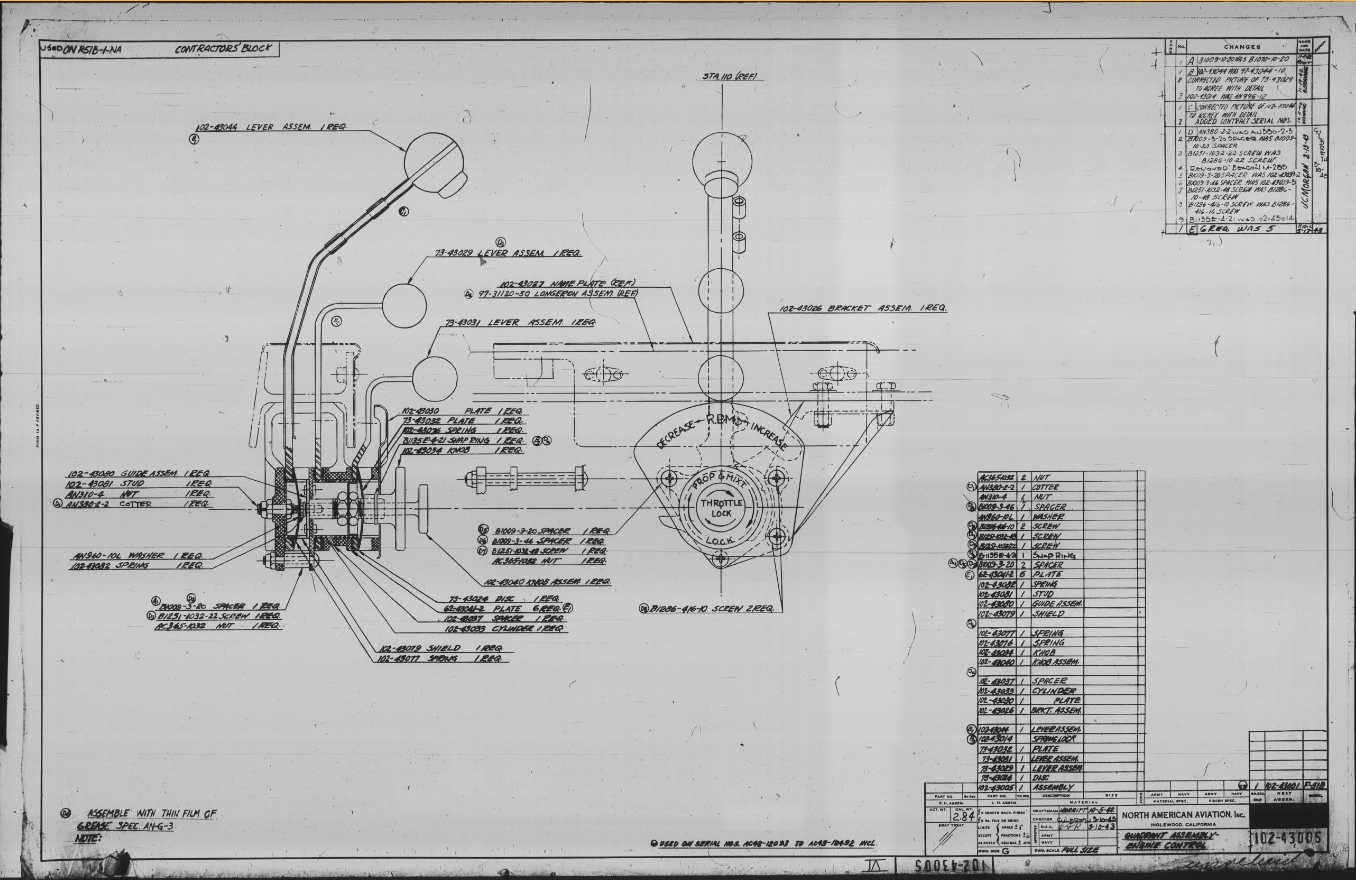
Alongside the P-39 Restoration project, I still develop several aircraft components for other aircraft. This includes my old favourite, the P-51 Mustang. This example refers to the Quadrant Assembly for Engine Control; drawing #102-43005 for the early P-51B.
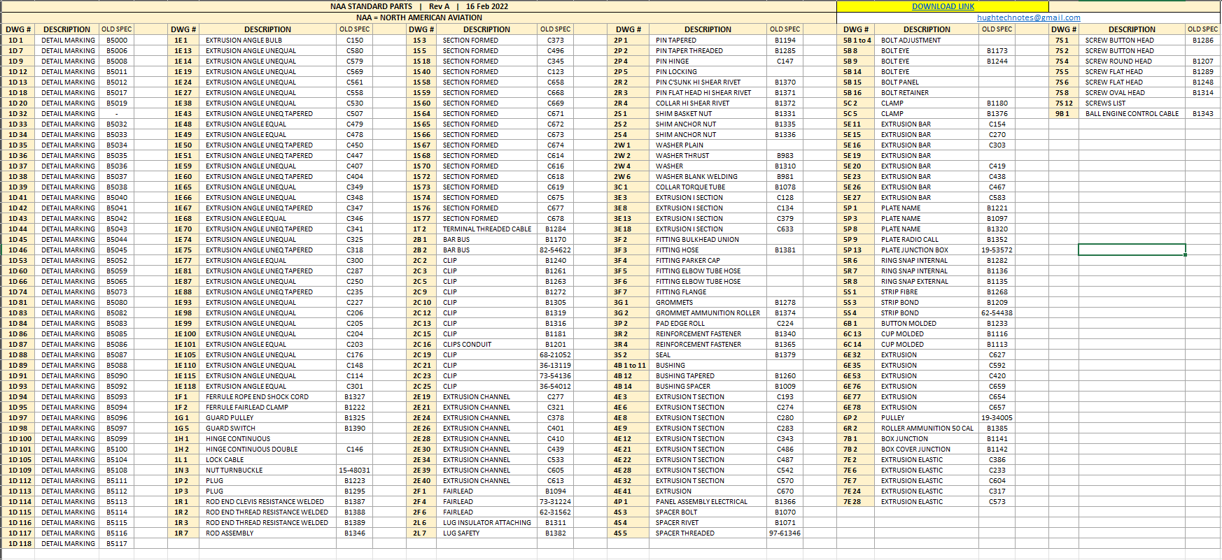
Many of the standard parts called up on this assembly use the early standard references. These are typically prefixed with “B”, like B1009, B1135, etc. These standards were later updated, and a new series of standards replaced them. I have correlated these in a spreadsheet, as shown below.
The spreadsheet only lists the standards that are available in the blueprint archive and may not be a complete record. For a more comprehensive listing, refer to the Erection and Maintenance instructions for the P-51A series (T.O. No. 01-60JC-2). Check the Conversion lists from pages 404 onward.
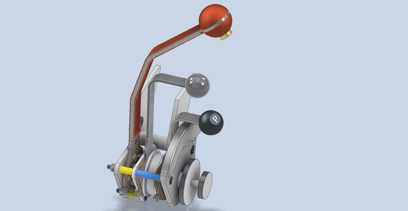
The CAD development of the Quadrant Engine Control is still a work in progress…created to the exact original dimensions.
My plan for the P-51 is to further develop the instrumentation for the early and later versions.
P-39 Update and Standards:
Over the last few months, the P-39N Restoration project has been my primary focus. We are close to completing the CAD work for the Cockpit instrumentation.
By contrast to the P-51 Mustang, we don’t have the same collection of Bell Standard part blueprints. We only have what is available within the manuals. However, the notations for the parts are similar for the industry as a whole. For example, a Spacer Part noted as Q065-6-20 shares the same notation for the dash numbers as the P-51 (standards 4s3 and 4S4). This in turn will define the spacer size…the first dash number sequence indicates the bolt size and the second is the length. In this case, it would be #6 bolt size. The length is defined in 1/32nd inch, making it 20/32″ (5/8″) long. This table derived from the iPart feature explains the designations in more detail.
The next time you come across a part reference you are unsure about, cross-reference it with other aircraft-known standards. Also, consult the comprehensive collection of AN and MS standards on Everyspec.com.
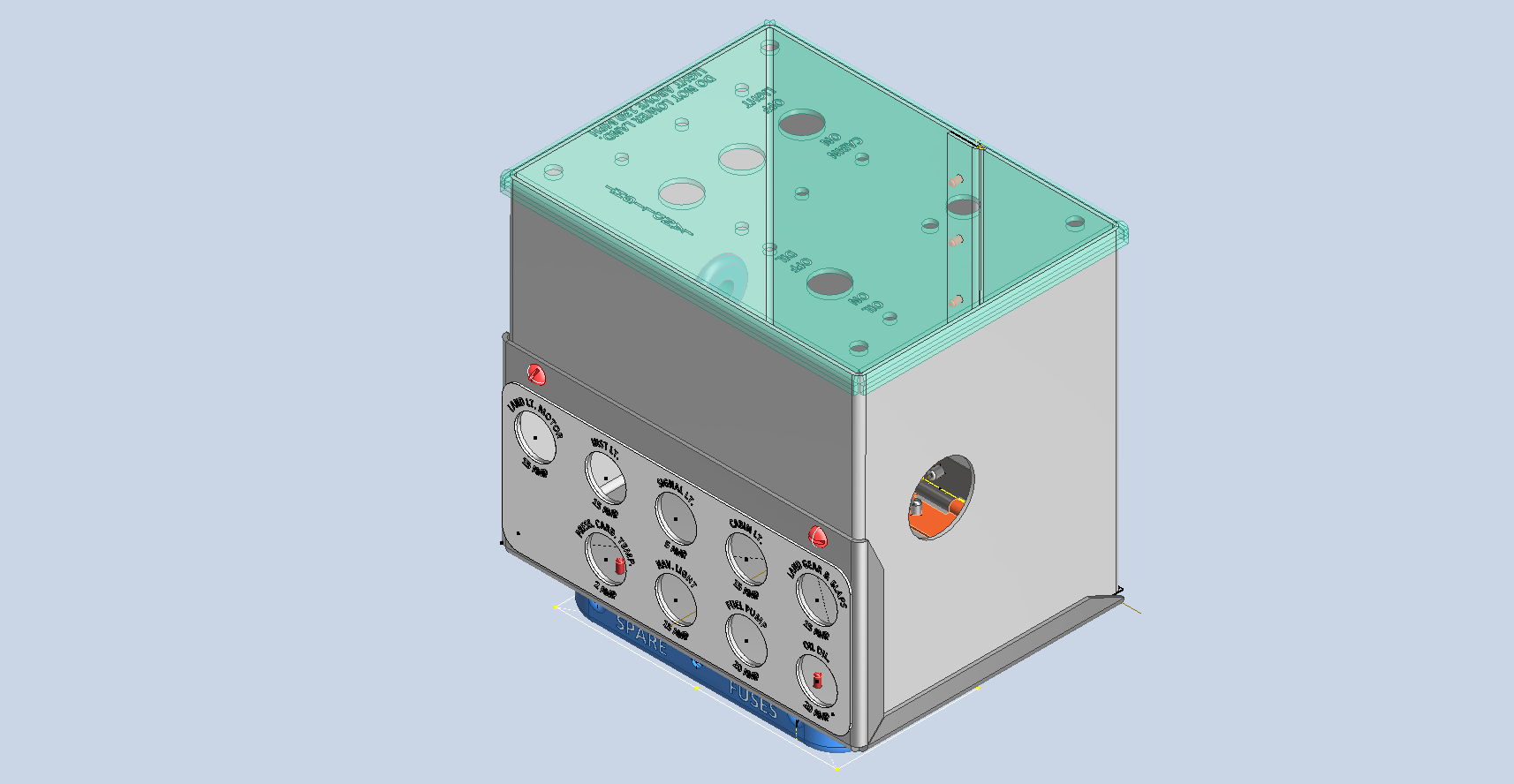
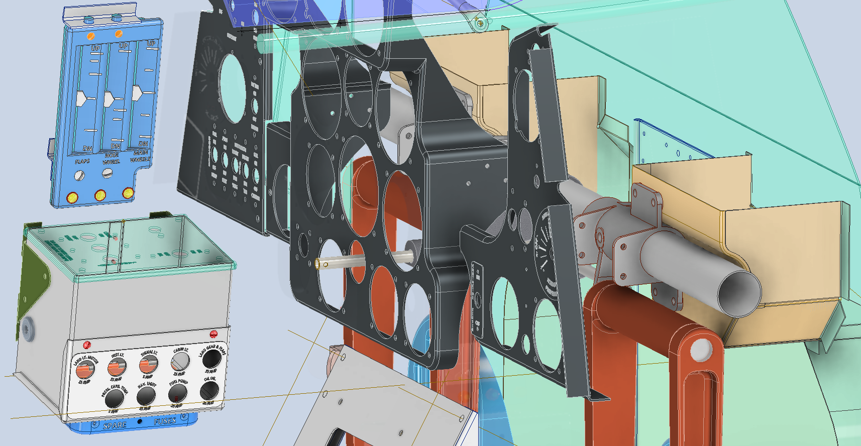
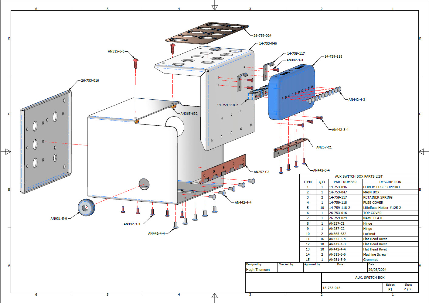
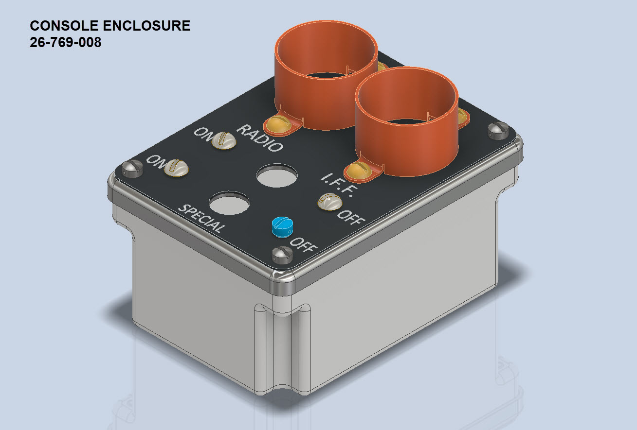
A quick update on progress with the P-39 Restoration CAD work. The final CAD models and accompanying 2D manufacturing drawings were issued this week for the Radio Console…so hopefully that will be built soon and I can share some of the installation photos when that is done. The exploded views as shown are the cover sheets for each assembly. Every part is fully dimensioned and detailed on separate sheets.
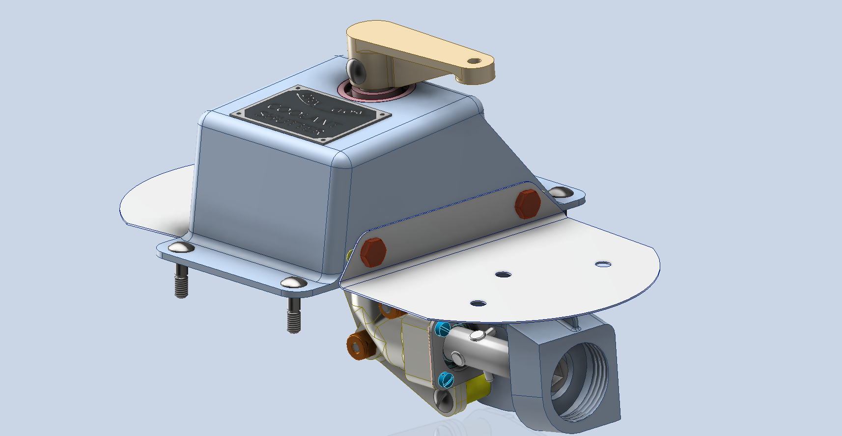
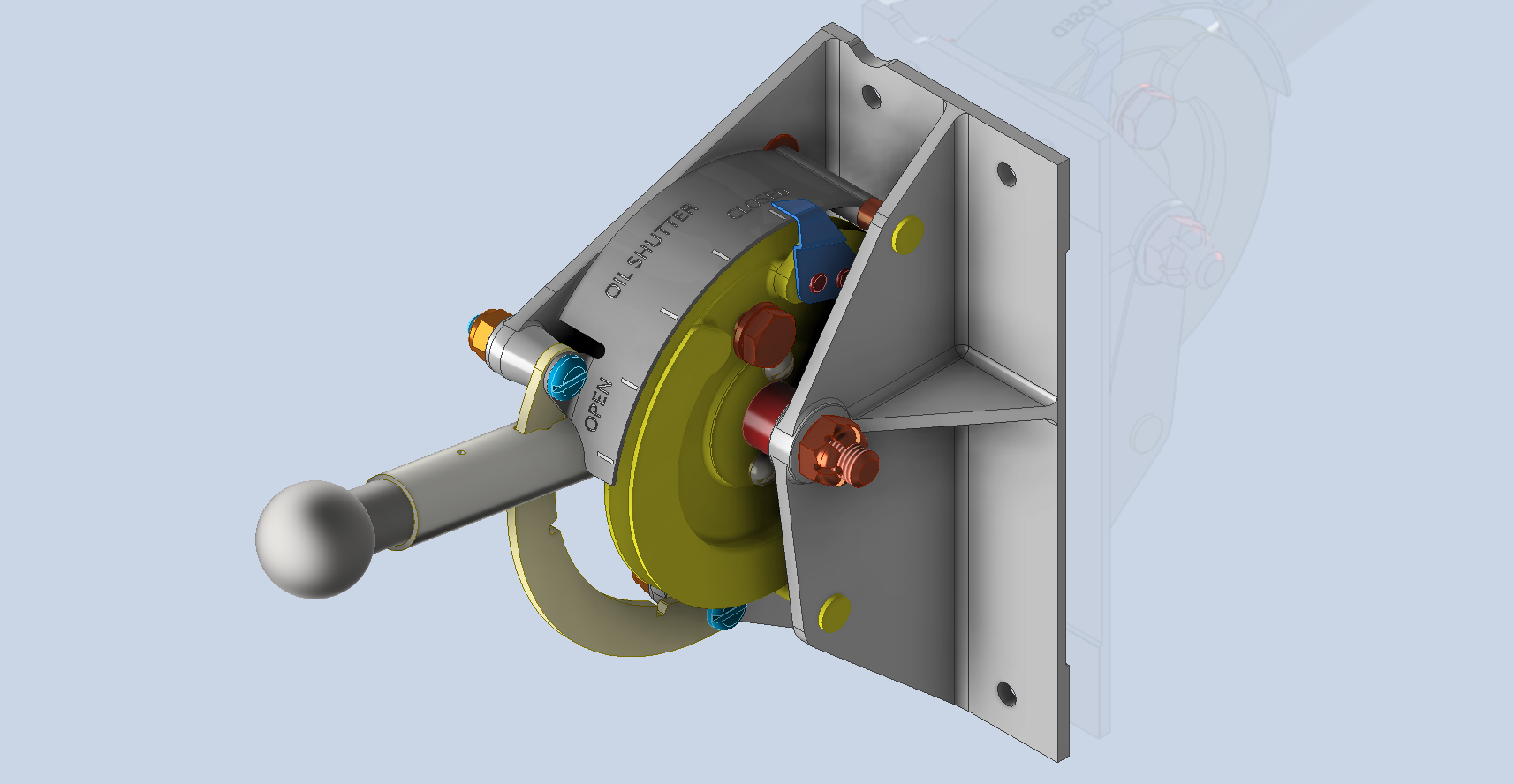
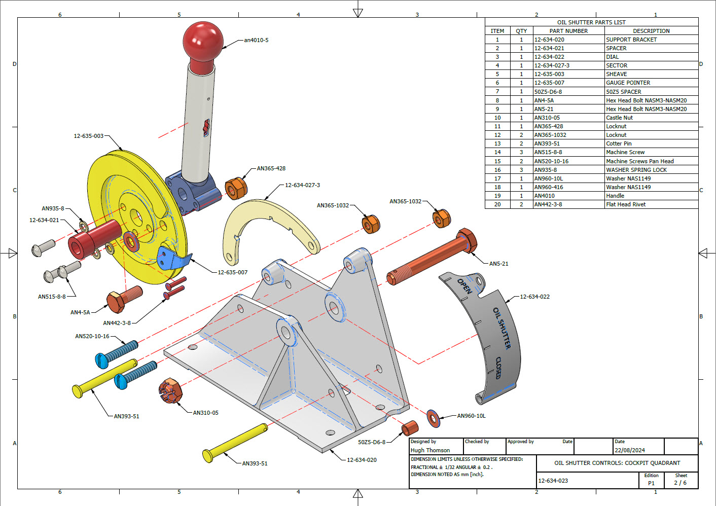
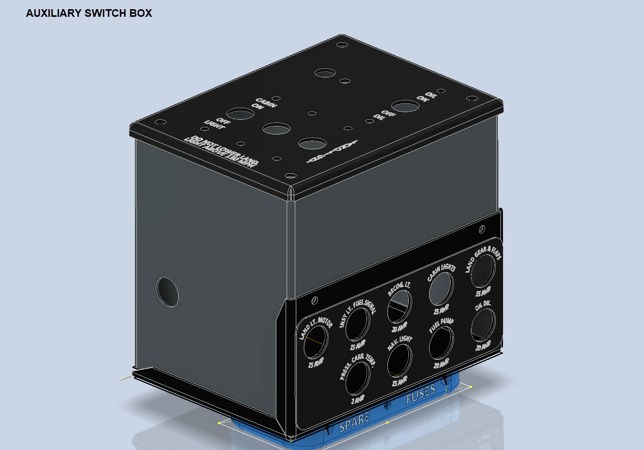
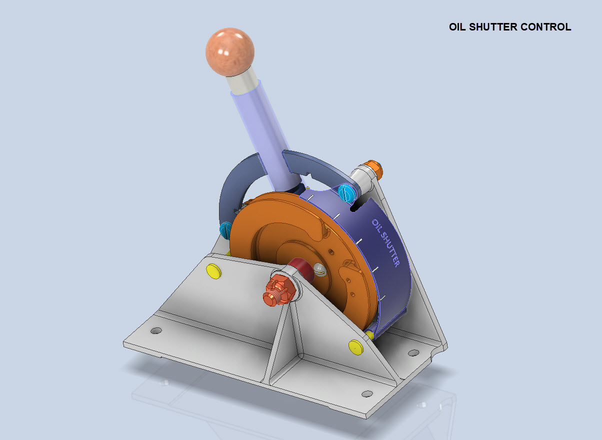
In addition, the Oil Shutter and the Auxiliary Switch Box are well-advanced in the CAD development stage. These are currently in abeyance while we check the availability of some of the components.
To compliment the Oil Shutter and Aux Switch Box CAD work I have also developed a few basic component assembly videos that are now on YouTube.
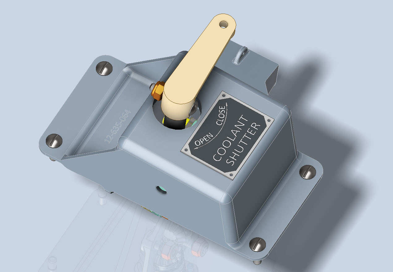
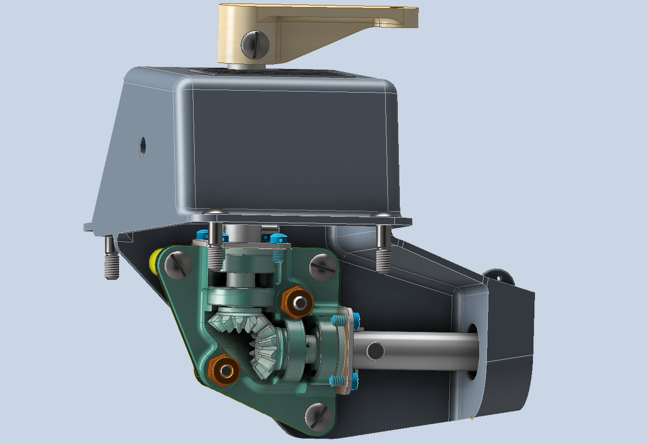
Have now almost completed the Coolant Shutter CAD model for the P-39. All bolts, rivets, nuts and screws are modelled to exact AN and MS standards. Hopefully, in the next week or so I will do an assembly video and upload that to YouTube…so stay tuned for more updates.
A quick note on relevant standards for bearings. The Bell drawings typically refer to type “K6A” or “K8A” which is equivalent to the AN201 standard (not the AN200 that refers to types KR6 and KR8). The AN201 standard was replaced by the MS27641, which in turn was cancelled in 1995 and replaced by SAE-AS27641 (dated 1998).
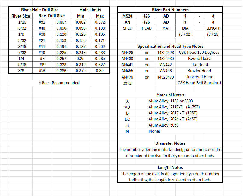
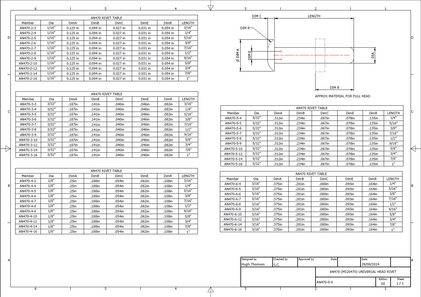
Developing the CAD standards for Rivets has been on my to-do list for far too long..so with the progression of the P-39 cockpit instruments it has become a priority. Typically on the Bell drawings and other aircraft manufacturers’ drawings we may only have the hole sizes noted, the rivet designation or information pertaining to the same but unreadable. Also occasionally even when we do have the hole sizes and the rivet designation often we don’t have the length required.
Something needed to be done to make this task a lot easier, particularly when you have instrument panels that incorporate many different types and sizes of rivets.
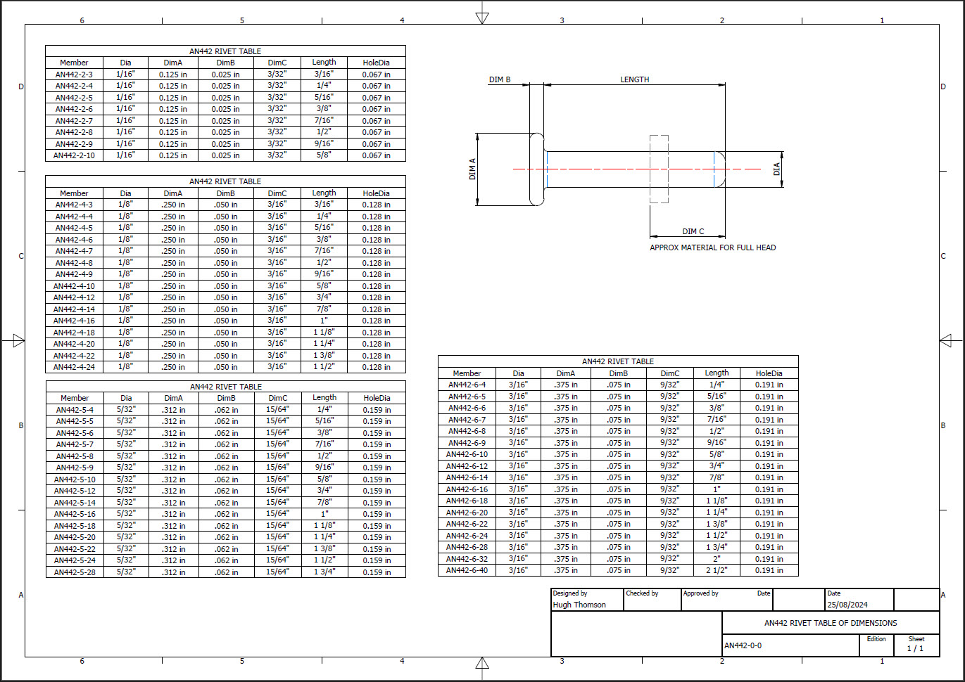
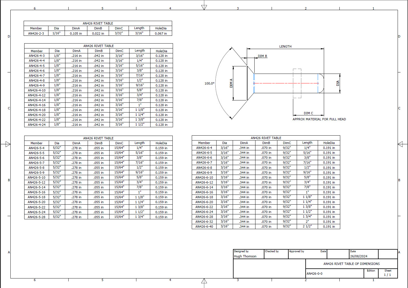
The first part of the process is to create several parts for the various types of rivets; which at the moment are listing the most common sizes I need right now. You will notice that the Rivet Name does not include the material type as doing so would require an extraordinarily large table of data. So the name is simplified to make this task easier to correlate but also because the priority at this time is dimensional correctness for rivet type, diameter, hole sizes and rivet length. At some stage, I will invest some time into deriving the various information sources to correctly name the rivets according to the AN and MS standards.
To complement the CAD iParts I also have a few spreadsheets listing key parameters and fabrication criteria.
The above tables are self-explanatory with the inclusion of a designation for a Bell Standard Rivet 35R1. I have actually found dimensional information for this type which I will include in the CAD library. This is where things get interesting because of the scarcity of historical components that may no longer be available, it may be necessary to find suitable alternatives.
You will notice that the Rivet Grip tables are in inches and mm…as I tend to work using metric mm templates (although the dimensions are input as inches) it makes it easier to measure the material thicknesses in mm and determine from that the rivet length. There is a technote somewhere on my blog that describes the process of inputting inch dimensions in metric mm templated models.
This will be an invaluable asset moving forward with the cockpit rebuild on the P-39. For example where there are issues with the legibility of key information on the Bell assembly drawings I can refer to other connecting part drawings that may only have hole diameters but will be sufficient to determine the correct rivet type and size.
This is very much a work in progress and will be updated as needed.
Update: 28th August 2024:
I have updated the Rivet CAD files which now include AN426, AN430, AN442, AN470 and of course the Bell standard 35R1.
All Rivet CAD data files (iParts) are now included in the CAD Standard library (see CAD resource tab for further details) along with original spreadsheets of Rivet Grip and general details.
The P-39 Restoration project was rather busy last month. The chaps at PoF have completed and test-fitted the Drive Shaft Cover fabrication and the Floor panels for the Rudder Quadrant…all is good. The Radio Console is now designed with the 3D CAD models and fully dimensioned 2D drawings; for all parts; issued for fabrication…I am looking forward to seeing the finished product.
Several other components are still works in progress with the CAD development well-advanced. These are for the Auxiliary Switch Box and the Oil Shutter Control. I still have the detailed drawings to do for both of these assemblies, which hopefully I will get done in the next few weeks.
Today the importance of fully dimensioned and detailed 2D drawings is commonly overlooked. It is an essential part of the process to both check dimensional accuracy and also to ensure that the clearances and fabrication tolerances are correct. So I tend to do 2D dimensioned drawings for everything, even items we know in advance that will be 3D printed. All the assemblies include all the necessary bolts, nuts, screws, washers and other standard components in compliance with the requisite AN and MS standards.
As you know I already have a fairly comprehensive library of over 350 parts parametrically modelled in CAD, which although comprehensive will at some stage require the addition of more components as highlighted by this particular project.
The current library is available on the CAD resources page, which will save you a lot of time and effort on your own projects. Although these CAD files are aimed at Inventor users you can quickly download an evaluation copy of Inventor from the Autodesk website and convert them to any CAD format you need.
Please consider making a small donation, even the cost of a coffee will help support my work on this project and the research work on other aircraft.
As usual any comments or feedback please drop me a line at hughtechnotes@gmail.com
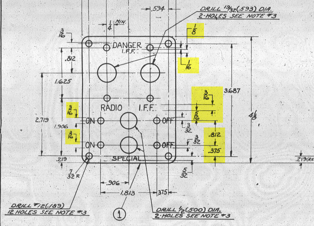
For instrumentation Panels, the location and size of text is very important to ensure clarity. This is usually well documented on the manufacturer’s blueprints so it is essential we get this right. In Inventor for example and I am sure it is equally similar in the many different CAD programs the key is the Text justification…let me show you.
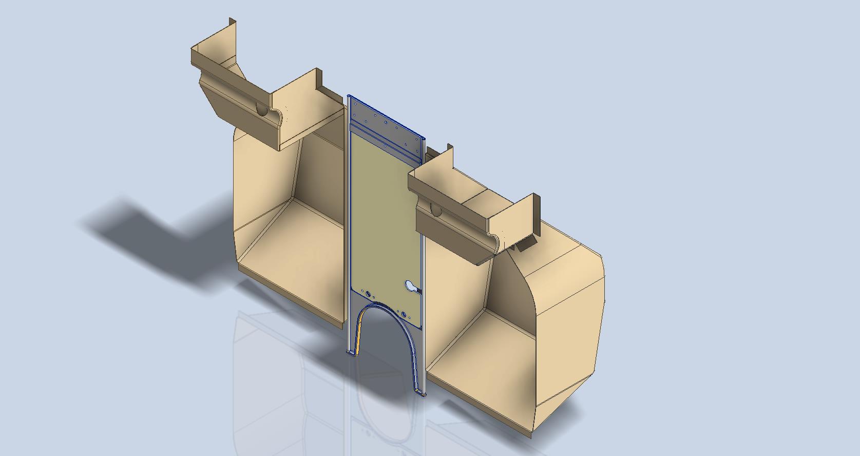
First of all a quick update on the P-39 Restoration progress. Much of the recent discussions revolved around fabrication and 3D printing. As mentioned in the previous article this restoration is a static display for which many of the parts will be 3D printed, although the key aluminium panels will still be fabricated as such. The very latest part to be issued for fabrication is this small Switch Box on the Radio Console.
A surprisingly complex box which will be 3D printed and the Nameplate will probably be CNC. The dimensions of the main box are not defined on the Bell drawings so I had to interpolate from the known information and other Bell references to determine the final dimensions. This took into account the clearance from the Drive Shaft connecting flange which is in very close proximity to this box. This also fits quite well into our discussion here on Label Text Placement.
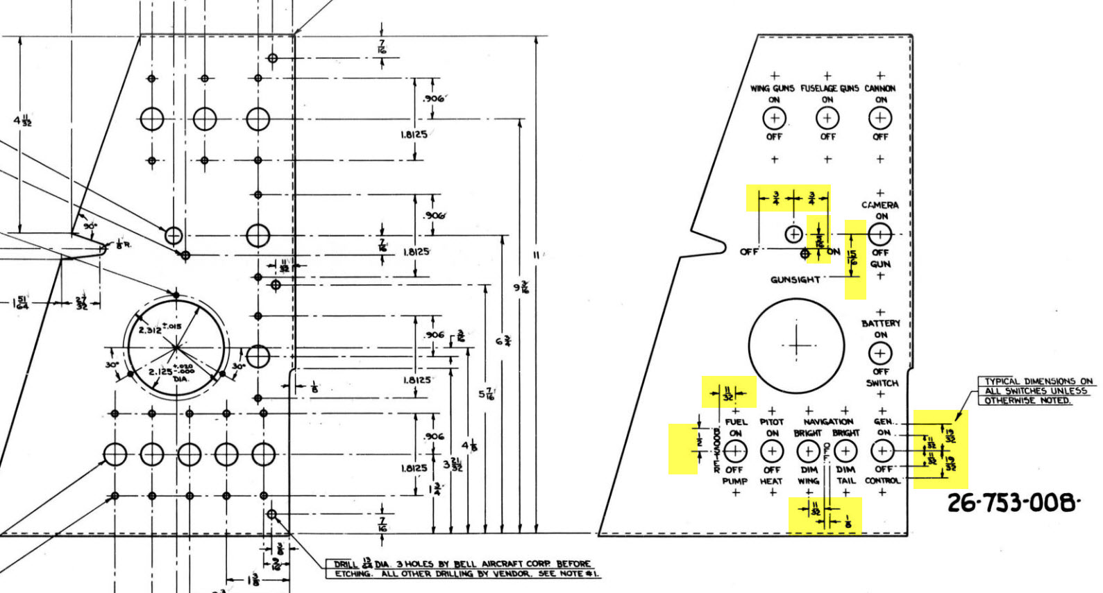
Typically on the Bell drawings, for example, the panel drawings include the height and location of the Label text similar to the following.
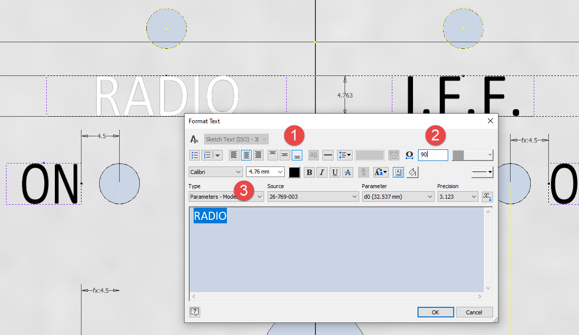
The way we do this in Inventor is by using the Text justification feature in the text editing box.
In the first image, we adjust the justification using the icons at “1”. If the dimension to the text label is to the bottom of the text we set the vertical justification to the bottom and if the placement horizontally is to the centre we centre the justification. When you exit the Text editing box a Text outline box is shown in dotted (this is optional so make sure you switch that on). The appropriate edge of the dotted line frame automatically aligns with the justification of the text entities. This dotted outline can be dimensioned and constrained as you would any graphic sketch entity. The second image shows some examples of how the dimensions of this outline relate to the justification.
It is not unusual for the overall width of the label text to also be specified in which case the “Stretch” value can be adjusted accordingly, entity “2”. At “3” we set the font and height, make sure you have the text highlighted in all cases or these adjustments will not be applied.
Interesting to note that the text outline can be useful if you require a frame around your text. The dotted lines can be changed to normal sketch lines and extruded or embossed as required.
There are a lot of features in the text editing dialogue which I may do as a technote further down the line but for now, to get the label text in exactly the right locations this is the way to do it.
Blimey I can’t believe I haven’t posted any updates since April…so I thought I should post an update as a lot is happening. The P-39 Restoration has been a particular focus of attention these last few months, with a particular emphasis on the Cabin rebuild.
P-39 Access Door Sta 86:
P-39N-5 cannon Access Door at Sta 86 positioned between the Rudder Pedal footwells. This took a while to create in CAD due to the complexity of the rudder footwells which are only required for positional reference.
The Footwells do exist which means we have a baseline to check the dimensions in-situ before fabrication. All the original CAD 3D models are provided to the restoration shop along with fully dimensioned 2D drawings.
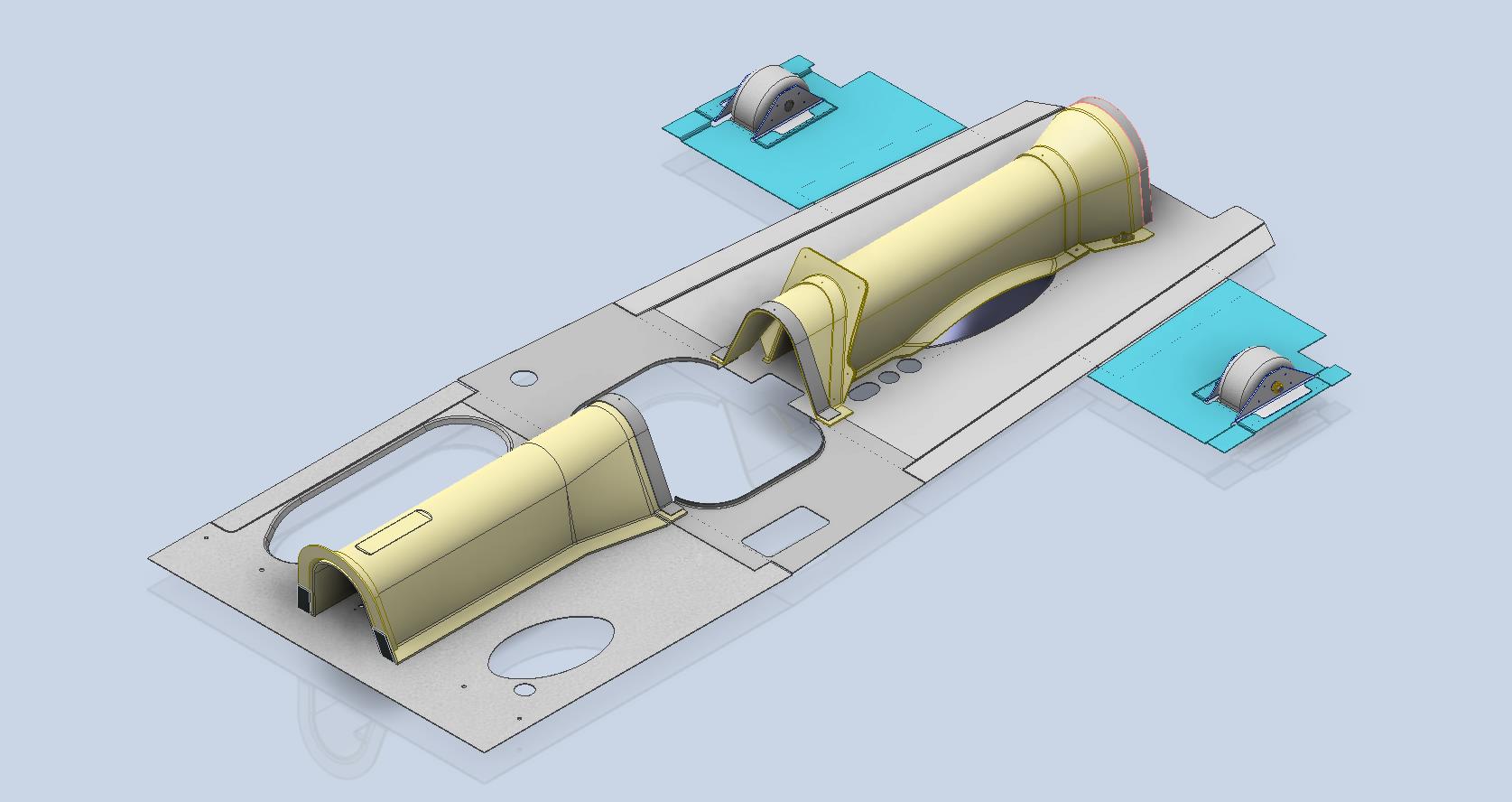
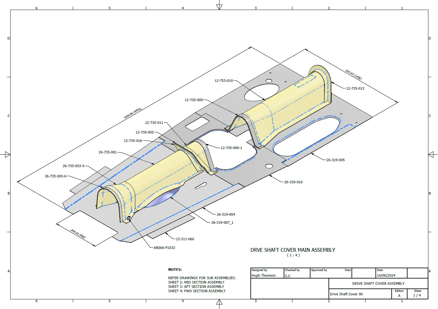
P-39 Drive Shaft Cover:
P-39N-5 Drive Shaft Cover was another interesting assembly because it was decided at the eleventh hour to 3D print the main sections. For this to work the material thickness has to increase to 0.1″ which meant that careful consideration was required to ensure that this change did not impact the interfaces with the existing bulkheads and the Radio Console.
The above images are courtesy of Omnica Corporation.
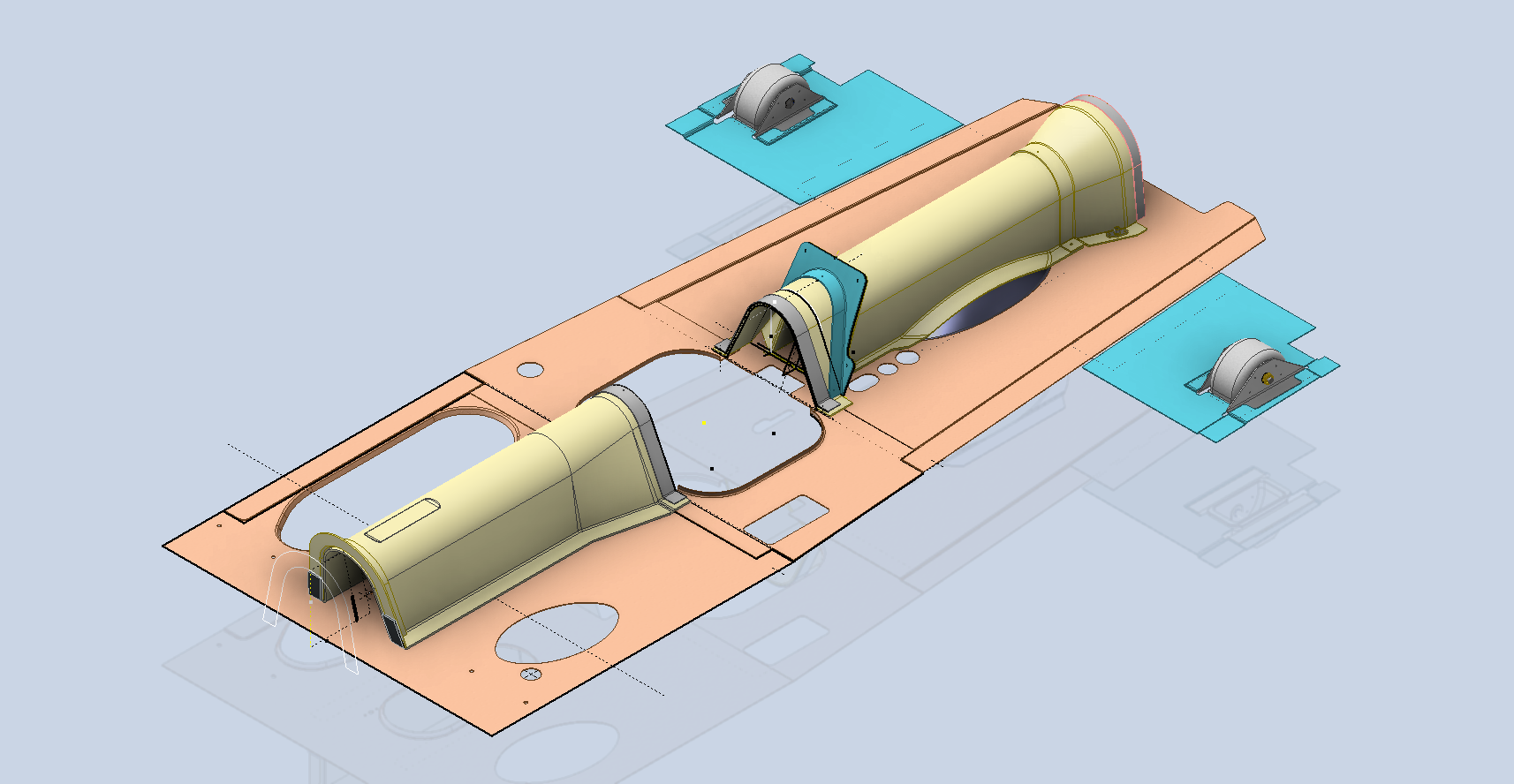
P-39 Forward Floor panels and Rudder Quadrant Covers.
As you can see the right-hand floor panel is missing and of course the relevant Rudder Quadrant Cover. The left side panel was also created in CAD because there was consideration for replacing the existing panel and Rudder Cover on that side due to the poor condition.
FM2 and P-47:
Moving on from the P-39 the FM2 project is currently on hold as my intent is to visit a few collections in the UK later this year to do further research, particularly the wing geometry. The P-47 has made its very first mention on this blog…another ordinate study for a friend which is progressing reasonably well but with the focus on the P-39 this will take a bit longer than I had planned.
P-51 Mustang:
The P-51 has popped up again after so many years…not an update per se but a new direction for me on the 3D printing side of things. As some of you already know I have been messing around with 3D printing for a while now mainly the SLA resin. Many moons ago I fully modelled in CAD the Tailwheel mechanism, some of which I had already 3D printed. The reason for revisiting this project is to 3D print more of the parts as a test bed for different resins to examine various structural properties, dimensional accuracy and of course, play about with different finishes. Also to determine just how thin I can go with 3D printed parts and still have a workable mechanism.
This P-51 is a side project that will help me devise solutions for the ultimate goal which is to replicate flight instruments and controls.
As you know original instruments for these aircraft can be very expensive and just furnishing a static display restoration project with the original instruments somehow seems a waste when a replica would be sufficient. This way we can make available the original instruments or parts thereof for refurbishing/restoring for an actual flying aircraft restoration.
My budget for this is rather limited for purchasing materials and I also have limitations on the Elegoo Mars Pro print volume. However, I can work within these limitations…it just takes a bit longer! Something like the newer Elegoo Saturn Ultra would be a dream for this sort of stuff…maybe someday!
The resin I’m currently reviewing is the Anycubic ABS-Like washable resin which surprisingly is rather good…now I have the settings dialled in the detail and dimensional accuracy is exceptional. I will endeavour to test some of the engineering resins like the JAMG HE products though they do require a heated VAT. I see a lot of potential for 3D printing parts in the restoration of static aircraft projects. I would suggest organising the CAD workflow so the original parts are modelled to the manufacturer’s exact dimensions and adjustments made only to derived parts thus retaining the original details.
Another aspect of 3D printing worth exploring is for making molds and something else I am keen to try is whether it is strong enough for vacuum-forming thin sheet aluminium.
A lot is going on here at the moment with work continuing on the various aircraft whether that be ordinate studies, designing for manufacture or indeed exploring the vagaries of 3D printing.