NAA P-51D Mustang: Fuselage: Conics

NAA P-51D Mustang: Fuselage: Conics

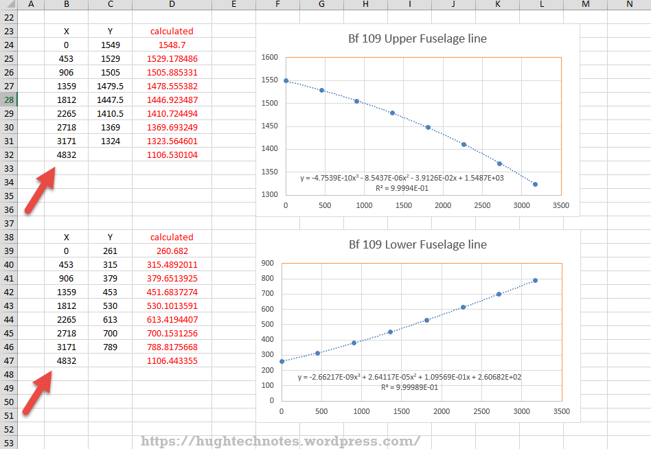
In the preceding article I had some fun with polynomials and how they could be useful for determining a smooth fit spline for the development of the Mustang fuselage. As a follow up to that article I wanted to share some research relating to conics.

The Mustang P-51 was the first aircraft to be completely defined by conics. The designer Edgar Schmued worked with Roy Liming to mathematically analyze the Mustangs shapes, tangents and curves. Conics were used by NAA as far back as 1932 though many of the techniques and equations we use today however were not actually in use until 1959.

The Bézier curves for example were based on the Bernstein polynomial which had been known since 1912 but its application for graphics was not understood till much later. Bézier curves were widely publicized in 1962 by the French engineer Pierre Bézier, who used them to design automobile bodies at Renault. The study of these curves was however first developed in 1959 by mathematician Paul de Casteljau using de Casteljau’s algorithm, a numerically stable method to evaluate Bézier curves at Citroën.

So I started to wonder how did Edgar Schmued and Roy Liming actually apply conic principles and what methods did they use for the Mustang design!

The documentation I have available for the Mustang Wind Tunnel models gives us a clue at the geometric construction for the fuselage frames. The designers used smooth conic sections with key parameters controlled by longitudinal shoulder and slope control curves. The longitudinal curves defined fullness and tangency values for the conics from forward to aft of the fuselage. The P-51 designers found that this technique allowed them to accurately control sectional areas to secure the required effects for lift, drag, stability, and overall performance.

2015-08-03_22-50-45

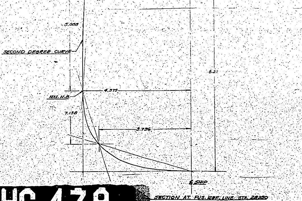
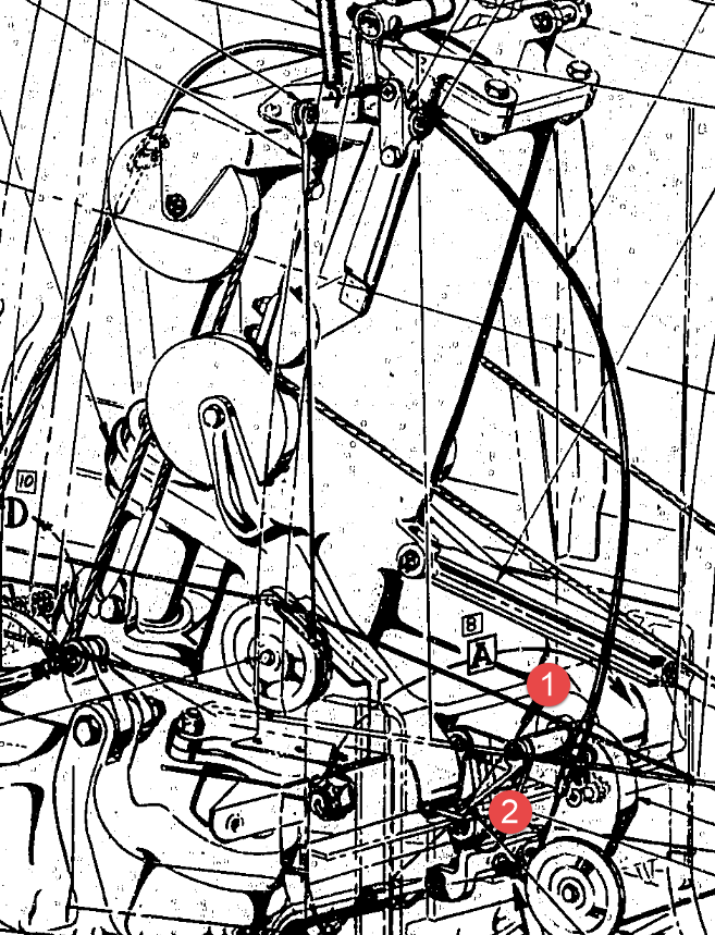
Here we see a scrap view from the wind tunnel models, showing clearly the development of the conic constrained by 2 tangent lines and a third Shoulder Point as a known point on the designed curve.

The intersections of lines extended from the Max Half breadth point and the Lower Ship Centre point illustrate a drafting technique for creating the finished curve for the lower section of a fuselage frame.

Hugh P-51 ConicsTaking this method further we can describe a curve using a series of extended lines to define any point on the curve as shown in my Cad drawing.

This is my interpretation of a technique for the drafting of a typical Mustang fuselage frame. I haven’t seen this technique applied to a full fuselage profile and whilst the design information I have suggests a similar approach by the Mustang designers I can’t verify that this was the actual technique used.

It is not possible within the scope of this article to go into the detail of this technique, but suffice to say that selecting only 3 points for the lower and upper sections contained within tangential lines provides the basis for accurately determining any other ordinate point on the particular curve. I have uploaded a short video on Youtube here: Drawing a Conic

This is actually a lot better than using the polynomial equations for frame geometry as they only give you a best fit approach based on the tabled ordinates; with limitations; whilst this construction technique will allow the flexibility of defining any point on the curve to an unprecedented degree of accuracy when created in CAD…it works!

So what else did these visionary guys do? I am really keen to further research the mathematical approach that Edgar Schmued and Roy Liming used in the other aspects of the aircraft design and uncover the methods that made the Mustang unique.

It is my hope that by sharing my research and developments that this will inspire others to also research the work of the designers from this era and hopefully in some small measure encourage support for our project “Operation Ark”.

2015-08-06_03-06-27
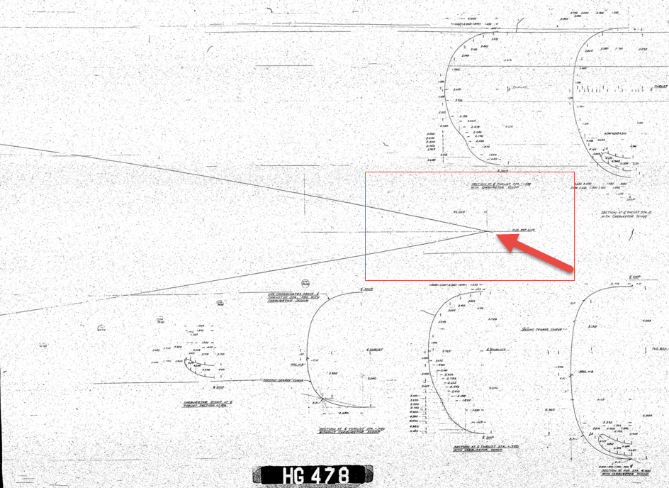
Update: I must have spent a full day browsing through the archives to find more information that would assist with understanding the conics development and thankfully I came across this NAA lines drawing for the cowl on P-51C (NA-103).

This shows the development and tangent lines for everything including the shoulder lines and the fairing lines as well as the main profile contour lines.

Its very important to spend time verifying the information used for developing these designs to validate the research. Sometimes I could spend days just looking for small scraps of information just to verify one dimension, which happened quite a lot on the Ta-152 project!

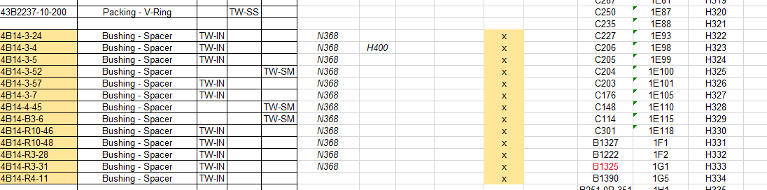
Full profiles drawn in Autocad from comprehensive excel spreadsheet ordinate collections now available for download. See this article for details.

NAA P-51D Mustang: Fuselage Lines; Polynomials

NAA P-51D Mustang: Fuselage Lines; Polynomials.

This evening I spent some time looking back through some old notes I had on fuselage design, particularly Conic sections and Setting-out design theory.

Checking through the archives for the Mustang P-51 we have a design set for the wind tunnel model with a line plan showing the Shoulder Points (SP) and the “point of convergence” where the upper line of the Mustang fuselage converges with the lower fuselage line and the Fuselage reference line.

2015-07-31_03-40-50The Wind Tunnel drawings are a quarter scale but are quite accurate.

Here we can see the “point of convergence” actually defined on the the wind tunnel drawing at the scaled sta 92. Technically station 92 does not exist as it is outwith the fabric of the WT aircraft, but for convenience I have defined it!

So with this in mind I decided to undertake an experiment to calculate the “point of convergence” with the fuselage ref line according to the manufactured ordinates.

2015-07-31_12-43-55For this exercise I used the upper line of the fuselage, shown here as X,Y values starting from Station 113 and created a line chart.

I applied an third order polynomial equation to the line chart with a scientific value to 5 decimal places to increase the accuracy.

I recalculated the values of the Y ordinate to check that the formula produced an accurate result; shown in red. As you can see the resulting values are very close to the original Y values.

The last X value is the projected value I want to calculate to achieve a “close to zero” Y coordinate thus by definition being the calculated “point of convergence”. This value is 9518mm (374.725 inches) which compares quite well with the Wind Tunnel drawings showing this to be 92*4=368 inches.

Should I recreate this exercise but instead use a fifth or sixth order polynomial equation I am quite sure the resulting value for the point of convergence would be closer yet to the scaled up wind tunnel value.

Normally for this type of exercise I would work with tangent lines and the start points of the upper and lower fuselage lines from predefined Shoulder Points.

This was a bit of fun just to demonstrate how we can use the power of spreadsheets and mathematical equations to assist with developing our Cad designs.

Bf 109Update: I decided to play about with this a bit more and had a look at the fuselage lines for the Bf109. I don’t have the design “point of convergence” for comparison but decided to do it anyway to find the convergence between the Lower and Upper fuselage lines.

These points are measured from a ground datum at 800mm below the fuselage reference line.

The stations/frames are from 2 – 8 inclusive. As you can see the calculated values verify the existing ordinate dimensions with the projected “point of convergence” calculated at 4832mm from station/frame 2.

These are the fuselage lines on the vertical plane which in theory should share the same convergence point for the fuselage lines on the horizontal plane (technically plan of max width)…an exercise for some other time!

What is even more interesting is that a line equation can be used to generate a spline in both the Inventor & Solidworks cad products… as a check to verify the cad work this is enormously useful!

2015-08-01_00-02-16Another example of application would be for the frames or station profiles.

In this example I have applied a polynomial equation to a set of ordinates for the top section of station 300 for the P-51 Mustang.

This needs a full profile as an arc to achieve an accurate result, which I’ve applied as a sixth order polynomial…you cant get much more accurate than this with Excel!

Ideally we would wish to extend this arc to the max width ordinate, which would add another negative ordinate (below the base line) to the graph…for some unknown reason Excel finds it difficult to compute an acceptable polynomial with 2 sets of negative values, so I would have to transpose the ordinates accordingly.

The Mustang ordinates induce a minuscule negative curvature on the top rear fuselage frames when you create a CAD profile just using the ordinate values from the NAA drawings. Its not detrimental in anyway but it is rather annoying…so to obviate these issues I could utilize a polynomial solution to adjust the ordinates to get a positive curvature. The adjustment is micro millimeters, but hey that’s the way that CAD works.


Mustang P-51CAnother Update:
Out of curiosity I recalculated; to a higher degree of accuracy; the upper fuselage line for the P-51 and contrasted that with a similar calculation for the lower line of the fuselage.

The calculated point of convergence of both lines based on a 4th order polynomial to 5 decimal places is at 9375mm and slightly above the fuselage reference line at +18mm. Factoring in error based on the original ordinates being accurate to 1/16th inch and possible error as a consequence of a higher order polynomial I think this is a reasonable result. Its interesting to note the variation with the results we got before.

This is certainly closer to the expected values based on the wind tunnel data. The squiggly line by the way on the lower part of the fuselage is the plotted max half breadths; which is rather interesting!

Confirmation; have received confirmation that the intended point of convergence for the upper and lower fuselage lines is at Sta 368, which is at 9347.2mm…this is great!!

All CAD profiles included in the P-51 Mustang Ordinate Package now available. Refer promotion here.

NAA P-51D Mustang: Standard Part Models & Specs

NAA P-51D Mustang: Standard Part Models & Specs.

I have revisited the standard parts I have been producing for this project to verify that the information is correct and in compliance with the latest National Standards and specifications.

As mentioned previously I will be developing the parts for Bolts, Nuts, Washers, Pulleys Turnbuckles etc…in fact everything that constitutes a standard component pertinent to aircraft manufacture.

The parts specified for the P-51 are universal which have been updated over the years and superseded with new part numbers. These parts are suitable for reuse on other projects, in particular the forthcoming Operation Ark project.

To raise funds to support the “Operation Ark” project I have decided to make these 3D Cad parts library available for a small cost.

2015-07-26_15-26-24  2015-07-26_15-26-52

The part above is the Clevis End (Part #AN161), dimensioned in accordance with the MS21252P 2007 specification. All sizes are incorporated within an Inventor iPart model and in a separate spreadsheet.

“As from 2007 the parts covered by dash numbers shown on AN161 are canceled after 10 December 1971. Steel, carbon and alloy MS21252 parts are inactive for new design. Use only 17-4 PH stainless steel parts for new design and replacement for comparable alloy and carbon steel MS21252 parts and AN161 parts. The canceled AN161 parts and alloy and carbon steel MS21252 parts cannot replace comparable 17-4 PH stainless parts and should be used until existing stock is depleted.”

The CAD 3D model parts include both the AN161 parts number and the MS21252 Part number for comparison. The 17-4 PH number is not included in the model but is listed on the accompanying spreadsheet.

2015-07-27_20-05-59Currently only a few parts are verified; please refer to the Resources page for updates as additional libraries are made available or if you have a special request for a library to be created then drop me a line.

For further details send an email to hughtechnotes@gmail.com

NAA P-51D Mustang: Project Cad Technote; Smart Parts Vb

NAA P-51D Mustang: Project Cad Technote; Smart Parts Vb

I was looking at options for routing the cables in the tailwheel assembly. There is potential for a lot of ancillary routing for pipes and cables yet to be done in this assembly so I have deliberately shied away from the adaptive parts (which I am not keen on) and the typical pipe and cable routing functions.

Also the cables are comprised of end terminals and many are sleeved for part of their length, which would mean having to route several times if I was to do this using the routing functions.

What I really wanted to do is have a sub assembly that contains the cable with all its bits in one sub assembly file but using the coordinates from the assembly to ensure correctness.

Extracting point coordinates from an Inventor assembly is not that straightforward requiring as in this case a vb solution, but first I had to define the key points.

2015-07-23_02-51-10      2015-07-23_02-44-30      2015-07-23_02-46-01

I use the term “smart parts” and what this entails is for the parts or sub assemblies to contain additional geometry that will assist with other modelling activities like cable routing.

The image on the left shows the cables in this area with 2 key points 1&2 highlighted that are replicated in the 2 archive images. They define the straight section of the cable sleeve that is below and above the cable clips; the locations of which I have incorporated as points in the component sub assembly (last image). This sub assembly does not sit vertically in the assembly, the final position and orientation being determined by other factors which influences the final routing of the cable sleeve.

I have done something similar with the connection at the other end towards the left of the first image. At this stage I now have 4 points that determine the extent of the cable sleeve.

2015-07-23_03-13-17The next step was to go to the main assembly and extract the X,Y,Z coordinates of the four points from the fitted components.

I first select these and run a visual basic routine to extract the coordinates of each point and create a csv file which I import into excel which in turn is imported into a separate Cad part file.

It was then simply a case of running a spline through all four points and sweeping the sleeve profile.

The great thing about this is that the coordinates are relative to the origin of the main assembly so when I import the cable sleeve into the assembly I only have to constrain to the origin planes and it fits perfectly.

2015-07-23_03-23-16The cable itself will be done later in a similar manner which would be added to the sleeve part file as a multi part item or sub assembly using the sleeve centre line as part of the routing.

So no adaptivity, no complex pipe or cable routing just simple association through coordinate translations. The parameters of the sub assembly can be linked back to a spreadsheet so if the route changes I just re-extract the point coordinates and update the spreadsheet, which in turn will update the model.

To me this is a very tidy solution and maintains the integrity of the modelling hierarchy in accordance with the NAA register.

Using additional content in part files to facilitate other activities is very useful for examples like this and in fact any part that is associated with piping or cabling systems, particularly where you have cable clips or supports that need to be considered.

I should note that the extent of the cable sleeve is not exactly as shown in the first image due to the termination part not yet being modeled so I used something that was close at hand to demonstrate this principal.

If you would like a copy of the VB routine then please drop me an email and I will send it onto you.

NAA P-51D Mustang: Project Cad Technote; iParts

NAA P-51D Mustang: Project Cad Technote; iParts

When it comes to organising standard parts using a Cad system like Inventor there are various ways to achieve this. Initially I considered a custom content library or even an iLogic expression linked to a parameter spreadsheet but I settled on using iParts.

The main reason for this is due to the fact that I already have a plethora of data contained in many spreadsheets for everything from ordinates to document registers and at any one time one or more of these spreadsheets is usually open for reference. Therefore the iparts seemed to be the ideal choice by maintaining all the relevant data in a single Cad part file.

2015-07-15_22-54-16

A simple example of this would be for the AN960 standard washers. I could have done something really clever here as the actual part number contains references to the physical sizes and properties of the washers and I had thought it would be great to link the naming convention to the parameters.

However there is no real benefit to be gained from this and would have added a level of complexity that’s quite frankly unnecessary for this type of component.

We have 3 dimensions that define the washer; the Outside Diameter (OD), Inside Diameter (ID) and the Thickness (Thk). We also have a material type but the Cad library will need to be updated to include the specifics of the materials for a P-51 mustang, which is another custom job; so I have ignored it for now!

The above sketch shows the expressions of the parameters defining the relationship of the values as declared in the parameters dialogue; this is where it gets interesting.

2015-07-15_22-55-47I should note that the template and default units for this model is millimeters. The standard units for the washers is inches.

This image on the left is the parameters dialogue box to which I first added some user parameters (1) set to “inch” units. I then created the cad model dimensional parameters (2) and linked those to the user parameters (1) with the units set to “mm” (3). The wonderful thing about this is that Inventor will adjust the values based on the unit type automatically; so just by changing the unit type the value will change accordingly, which is verified in the nominal value column (4)…great stuff!
2015-07-15_23-05-30
This is the iPart creation dialogue, showing the table of values, input from the standard catalogs in “inches”.

Its very important that the original values are retained as “inch” units so that it is easier to check and verify the correctness of the information and traceability.

Tip: If I already had these values set-out in exactly the same format in excel I could just copy and paste the spreadsheet directly into the iPart table.

At some stage I will add the material values to the end of this table for each of the components listed. Some examples of iparts include the Locking Stud and Clevis Fork; colour coded to differentiate size..

Locking Stud Clevis Fork

The notion of working with different units is made so much easier by the capabilities of these cad systems. Essentially when inputting the dimensions in a model sketch the value of the dimensions will change if you select either inches or millimeters according to the default template units setup for the cad model; it will even work with fractions.

For example if you type in “3/4 in” for a dimension in a sketch based on the “mm” unit template then the actual value for the dimension will be “19.05 mm”.

Another example; 12 23/64″; for this you type in 12 leave a space then 23/64 followed by “in”…”12 23/64 in” gives us “313.928 mm”.

NAA P-51D Mustang: Tail Wheel Assembly: Update.

NAA P-51D Mustang: Tail Wheel Assembly: Update.

I shall need to temporarily suspend further work on the assembly model as the remaining parts to achieve a full build are created in a later version of the Inventor cad program and therefore not compatible with the version I currently have access to.

So this is as far as I can go with the assembly, though one could argue that it may be worthwhile including the necessary bolts, washers, turnbuckles etc, but to be honest most of this is planned as the final components in the build. The main reason for this is to ensure that everything aligns properly and works according to the design intent before plugging in all those connecting bits!

p-51d mustang rear fuselage

I have some tidying up to do with the fuselage frames and to develop that library I was talking about for the aeronautical standard parts and components…so perhaps this may be the time to get this done.

I also plan to do some 2d detail drawings for some of this modelling to record some of the key information that I have had to research separately from the archive resource and create the Bill of Materials structure that complies with the existing NAA documents for the complete assembly.

2015-07-15_17-17-08

The 2d drawings will also serve as a dimensional check as these objects were built in mm whereas originally they were designed in inches.

Its very hard to identify small dimensional discrepancies when just reviewing the 3d model!

So for now I probably wont be posting too much on the modelling side of things but may include some new cad technotes on the techniques I have used in this project.

NAA P-51D Mustang: Tail Wheel Retracting Hydraulic Cylinder

NAA P-51D Mustang: Tail Wheel Retracting Hydraulic Cylinder.

Hydraulics is not something I have had very much exposure to in my varied engineering career, so it was rather interesting to build this Tail wheel retracting cylinder and learn some new stuff about the hydraulic designs of this era.

All the component parts are fully detailed in the NAA drawing archive enabling a complete cylinder to be built with the pipe fittings added from the Inventor Content library.

P-51D Mustang Tail Wheel retracting cylinder 2015-07-13_00-46-34

The Autodesk Inventor product has a very comprehensive standard parts library which includes a wide variety of pipe fittings and components. The elbows and reducers are from the Parker range which are sized correctly but slightly different in style to the aeronautical standard parts which would normally be used.

I did modify the hex head for the reducer to size correctly with the corresponding AN912 aeronautical part to ensure correct fitting with the cylinder interface.

When I have time available I intend to create a special library for all these standard components that will correspond exactly to the specified aeronautical standards.

The blue support brackets on either side of the cylinder should actually be fitted to a sheet metal formed channel, which I don’t have the details for. There is a drawing for the P-51B/C models which will be similar to what I need but the lower station frames in this area are slightly different. I can’t be sure exactly how the channel should be fitted so I emailed a few companies that have been involved in the restoration of P-51D Mustangs to see if they can assist with either photographs of this area or even better some drawings!

2015-07-14_23-34-18 2015-07-14_23-03-35

NAA P-51D Mustang: Project Cad Technote Multi Body Parts

NAA P-51D Mustang: Project Cad Technote Multi Body Parts

The process of developing these drawings into accurate 3d models relies on maintaining the hierarchy according to the original NAA drawings, even if sometimes it gets a tad confusing when dealing with what constitutes a “sub-assembly” as I mentioned before.

The sub-assemblies I described as “Part Assemblies” as the assembly unusually comprises a fully detailed part inclusive of additional items like bearing, spacers etc.

I have reviewed my approach to how I deal with this and thought it may be prudent to write a quick note on this technique.

I am utilising the multi-part feature within Inventor for this, which allows you to model separate solid parts within a single part file and then create an assembly that comprises some or all of these solids.

2015-07-07_12-57-05

This is a scrap view from the NAA drawing showing an assembly that has 2 configurations based on varying paired angles with spacers and rivets as shown.

Each of these items has a suffix added to the part number i.e -1, -2, -3 etc.

These images give you some idea of how I have modeled this, with the first image showing the configuration of items 2 & 3 and the second showing the configuration of item 2 & 4; all in one cad part file.

2015-07-07_12-41-28 2015-07-07_12-41-49

The beauty of working with multi body parts is that you only need one set of sketches that can be shared between all 3 parts.

2015-07-07_12-42-16

The sketches are dimensioned exactly as the original drawing…I mention this because I would not normally dimension from the edge of an angle section (cut edge); its not really good practice!

The image on the left shows the feature tree within Inventor; listing the 3 solids with appropriate suffixes.

The part file name (at the top) comprises the NAA drawing number with a suffix noting the archive reference.

All I have to do now is create an assembly for each of the configurations and add the relevant spacers and rivets. This is done very quickly using the “Create component” feature. The assembly number will comprise the NAA drawing number suffixed with either a -1 or a -5 respectively.

2015-07-07_13-50-22Only assemblies created from a multi-body part will be suffixed with a numerical character, otherwise they will simply be suffixed with SA.

Using this technique we maintain the integrity of the NAA numbering system with an hierarchy that suits the CAD strategy.

In a previous post I discussed “as-fitted” parts; like bushes; that might be press fitted and and reamed thus dimensionally different from the manufactured part, so these will still be modelled within the part file to “as-fitted” state and not brought in as a component of the sub assembly.

NAA P-51D Mustang: Tail Wheel Project Update

NAA P-51D Mustang: Tail Wheel Project Update

This project is growing arms and legs; every time I check back to the NAA documentation I find yet another part associated with the assembly in this area.

I am beginning to appreciate just how complex the interaction is with all the parts that share this very small space and wonder sometimes if I will ever complete this task!.

For this period of build I have had to revert to an earlier version of Inventor; which unfortunately means many of the parts already modeled cannot be included in the assembly build at this time as the version variants from a later release will not be compatible with this one. Also the material finishes are not as good as the Inventor 2016 as you can see below.

So I am focusing my attention on building the supporting elements for the Tail Wheel mechanics; including the fuselage frames local to this area.

P-51D Mustang: Rear Fuselage

The fuselage frames are surprisingly complicated to build, partly due to the limitations of the software but also due to the flanges having to align with the surface form of the main fuselage as shown. I mainly used the sculpting technique but found that it is not possible to apply a fillet to the edge of a sculpted solid that is derived from a spline curve, so these had to be added when creating the lofting sketches.

I have added a few parts (where I can) for the tail Wheel assembly; these parts in blue; and also an additional component in yellow which is a Support Assy – Rudder & steerable tail wheel control bell crank. This part by the way was a nightmare to build trying to get all the edges to align correctly with the sloping webs.

I have mentioned before the importance of having quality copies of the original materials to work with and this particular archive (from FlugArchiv) was done to a very high standard.

2015-07-07_02-06-47Occasionally though you do get the odd drawing that is almost impossible to use but having gained some experience in developing these aircraft structures it was not too difficult to determine the missing information.

This is the one I have for the lower section of one fuselage frame.

NAA P-51D Mustang: Document Management

NAA P-51D Mustang: Document Management

An update on the organisation of the document management and archive register.

The USAF Parts catalog for the P-51 is organised by assembly and sub assembly types. For the Tail Wheel assemblies we have one main installation assembly and two sub assemblies for the Shock Strut and Steering Mechanism as follows:

2015-07-02_00-29-57  2015-07-02_00-30-32  2015-07-02_00-32-05

For the document register I have grouped the records and created separate worksheets that comply with the assemblies as setout in the USAF Parts List, listing the assemblies with a Category designation i.e TW-IN (Tail Wheel Installation) TW-SS and TW-SM.

2015-07-02_00-35-30

In the last column I have identified the NAA drawing by type; defining these as follows;

  1. Part: An individual drawing fully detailing a single part or item.
  2. Part Assembly: A fully detailed part drawing that includes additional fitted components like bearings, bushes or rivets.
  3. Main Assembly: A top level assembly listing individual parts, sub assemblies or components.

Note: The Part Assembly is technically a sub assembly which unusually comprise a fully detailed single part to which other elements have been added. Currently for this to work for me in the Cad environment I have maintained the part definition but modeled as a multi-part file. I may decide to change this to an actual Cad assembly file.

To clarify the above and ensure that all parts are accounted for I have created a sub listing of the contents for each Part Assembly as shown in the following scrap view:

2015-07-02_01-02-46

Some of the parts included in the Part Assembly are bushings, which are typically a press fit and reamed to a specified diameter. The bushing included in the Part Assembly is modeled to “as-fitted” condition, but as a matter of record I maintain a separate model file built to the “pre-fitted” manufactured dimensions.

I have also extracted a separate list from the USAF Parts List for the NAA standard parts from which I have identified the information I have in the archive and the data I will need to source elsewhere.

2015-07-02_01-13-08

The NAA standard part drawings in many cases supersede earlier standards for which we have a reference listed. I have these listed in this spreadsheet in 3 columns (on the right); with the first entry being the “Old standard”; the second as the “New Standard” and the final entry being the archive reference. I have had to do this as occasionally the drawings refer to the old superseded standards number.

At this stage I have all the records for the Tail Wheel assembly organised into manageable chunks of information so that I can track progress as marked and manage the eventual build of the final Cad model assemblies.