NAA B25 Mitchell: New Project B-25B,C,D
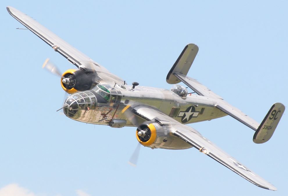
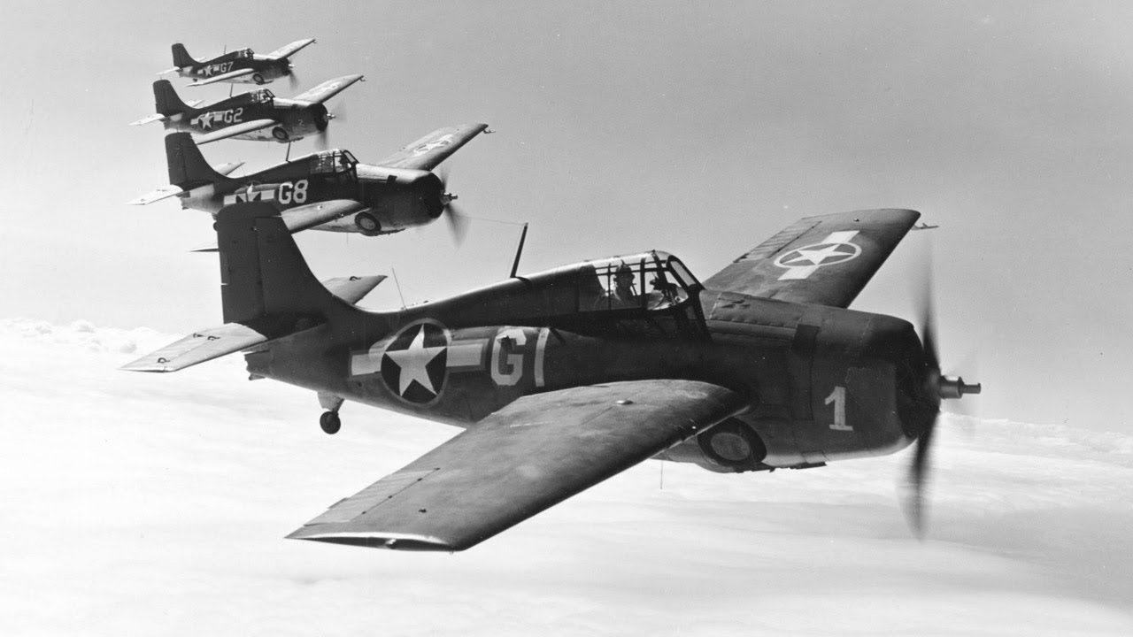
The North American B-25 Mitchell is a medium bomber that was introduced in 1941 and named in honour of Major General William “Billy” Mitchell, a pioneer of U.S. military aviation. Used by many Allied air forces, the B-25 served in every theatre of World War II, and after the war ended, many remained in service, operating across four decades. Produced in numerous variants, nearly 10,000 B-25s were built. These included a few limited models such as the F-10 reconnaissance aircraft, the AT-24 crew trainers, and the United States Marine Corps’ PBJ-1 patrol bomber.
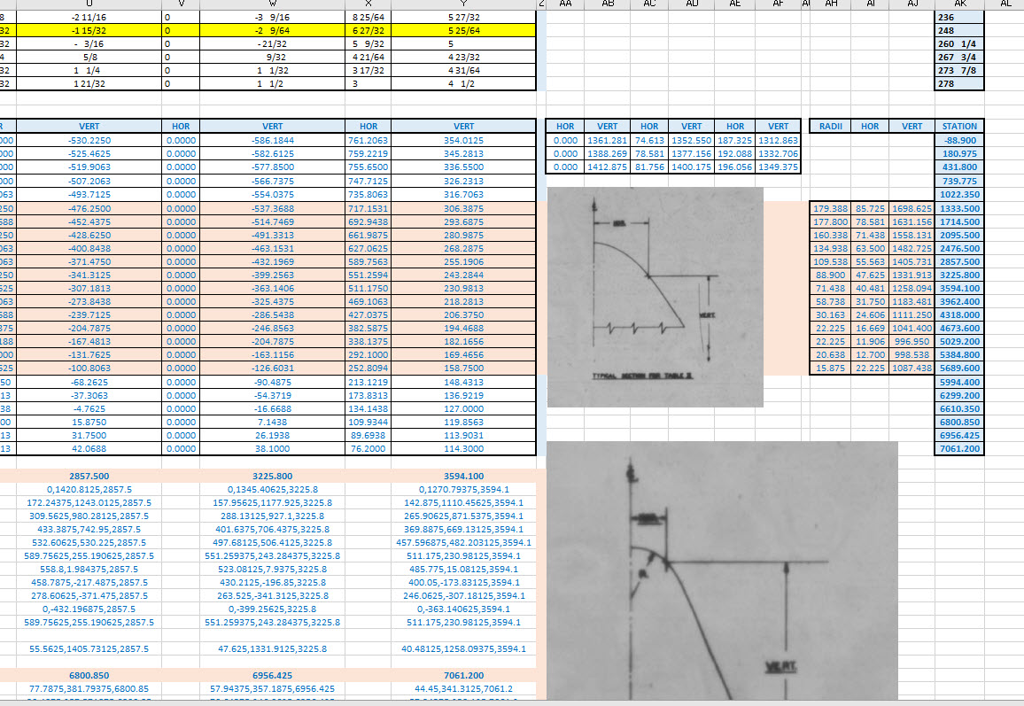
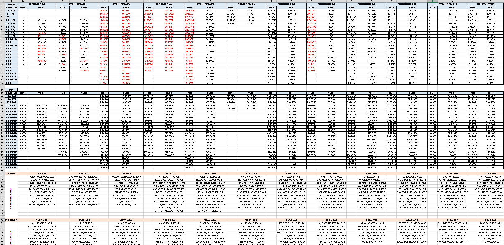
This project will be another research and study effort to develop the ordinate datasets similar to the P-51 Mustang project. The ordinate data is compiled from drawings, reports, manuals, documentation and correspondence so it does take a long time to do.


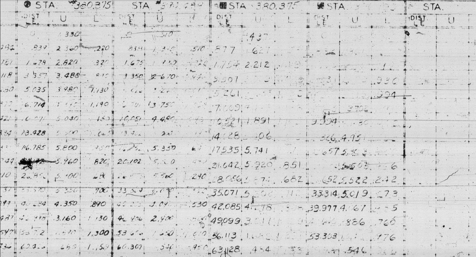
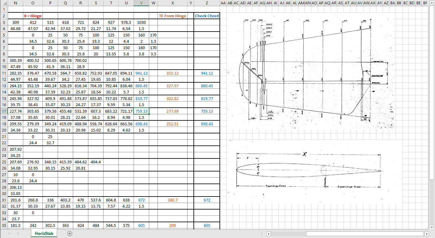
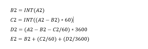
For example. the above spreadsheets show the work process, starting with recording the ordinates exactly as set out on the NAA drawings. In this case, the original ordinates are in inches so a second table is created to convert this data to millimetres. The third table is the transposed version; retaining original formula cells; which is then used to extrapolate the actual X,Y,Z coordinates for input into a CAD system (the first 10 frames are shown).

This table is the stringer ordinates which follows the same convention of recording the first table exactly as per NAA drawings then converting this to millimetres. The third step is slightly different; transposing the table data in 4 sections to align the data according to stringer number.

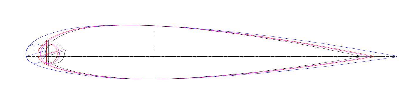
This last table is for the wing center section. The process is similar to the previous tables with the main difference being the extrapolated X,Y,Z coordinates originate from the 30% chord. The actual location of intersection between the wing chord line and the wing reference line is calculated at 33%.

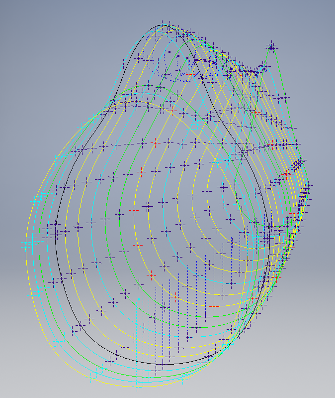
This is a lot of work just to get to this point I have spent in excess of 48 hours and I still have a long way to go. Once the frame X,Y,Z coordinates are listed they are then transferred to individual frames in the CAD system whereby they will be checked for accuracy.
There are a few ordinates that are illegible on the original drawings which will require further intensive research to determine.
To fully complete all the known ordinate spreadsheets for the B25 Mitchell I estimate will consume almost 300 hours of work. The P-51 Mustang set; created in a similar manner; was almost 3 times the number of manhours.
The end result is a comprehensive list of known coordinates that will generate the requisite fuselage, wing and empennage profiles within seconds in all major CAD systems…so it definitely is worth doing.

Fuselage total X,Y,Z points 2x 1043 = 2086
Wing total X,Y,Z points 2x 870 = 1740
Update 7th May 2020:
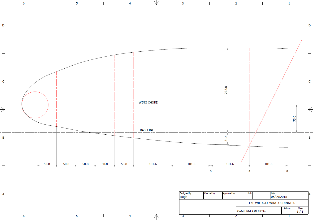
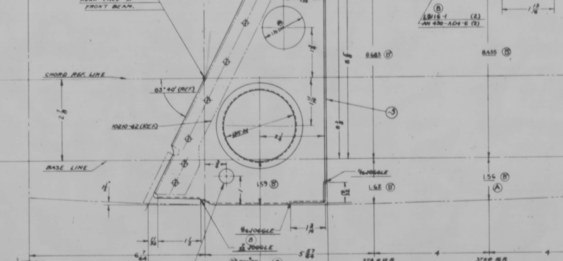
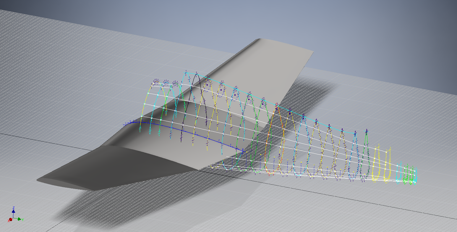
Continuing the development of the B25 Ordinate dataset I now have the majority of the wing rib profiles recorded. Some reconstructive work was necessary on the outboard ribs to obviate the poor quality of the original NAA drawings.


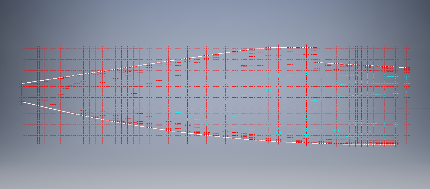
Every legible point is added to the spreadsheets and then meticulously created in the CAD system. Where information is unclear the cad extrapolated values are closely checked against the appropriate entry on the original NAA drawing to identify matching numericals or part thereof. Once I have consistency with the graphic output and the NAA drawing information this is then entered into the ordinate spreadsheet.
The attention to detail is typical of my approach to building these ordinate sets. Nothing is taken for granted and the primary reason why these datasets take so long to develop.


Update 12th May 2020: Project Status:
- Fuselage: Frame Ordinates and CAD Profile 100%
- Fuselage Stringers: Ordinates and CAD Profile 30%
- Inner Wing: Ordinates and CAD Profile 100%
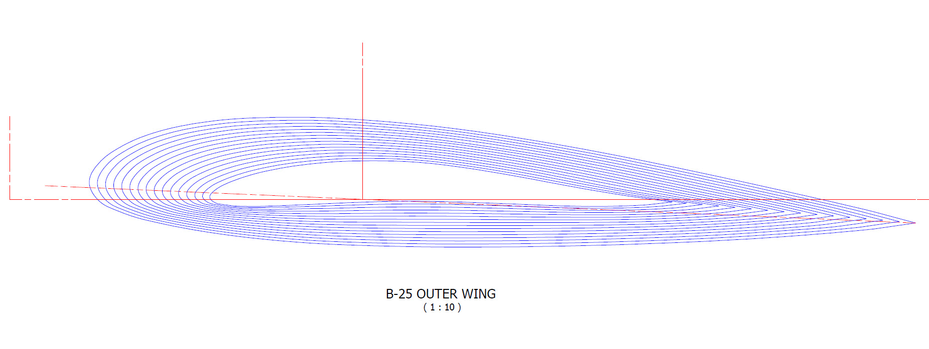
- Outer Wing: Ordnates and CAD Profile 100%
- Rudder: Ordinates and CAD Profile 100%
- Vertical Stab: Ordinates and CAD Profile 100%
- Horiz Stab: Work in Progress.
Update 16th May 2020: Empennage:


Update 19th May 2020: Rear Fuselage:

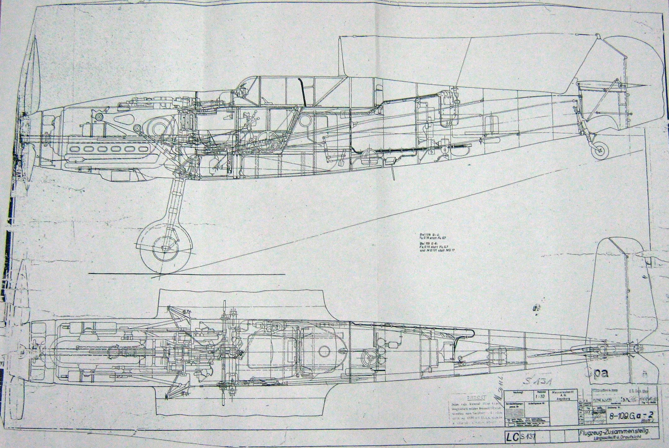
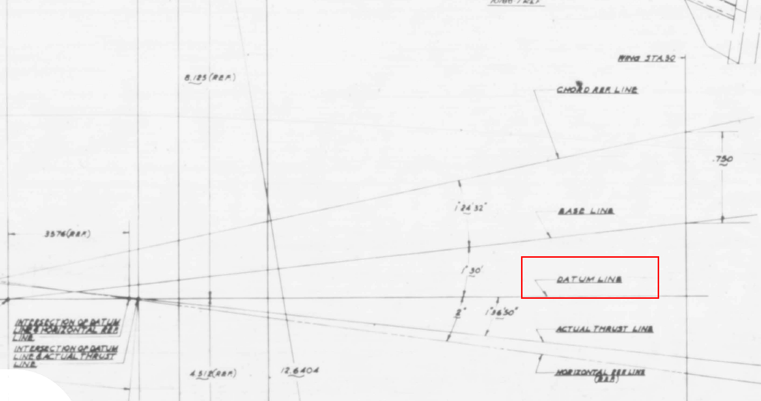
Often it is necessary to pull together several resource documents into one drawing to better understand key datum relationships as I have done here with the rear fuselage.
Update 21st May 2020: All Done:
This is a good example of what the ordinate datasets are all about.
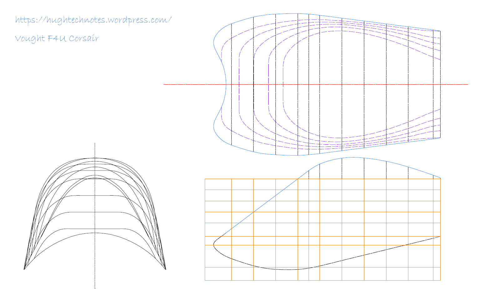
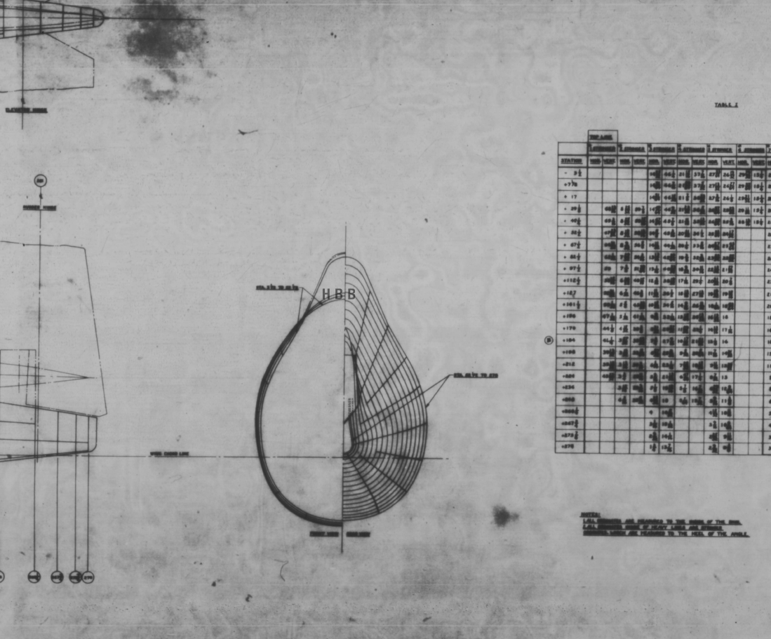
Making sense of this:
To develop this:
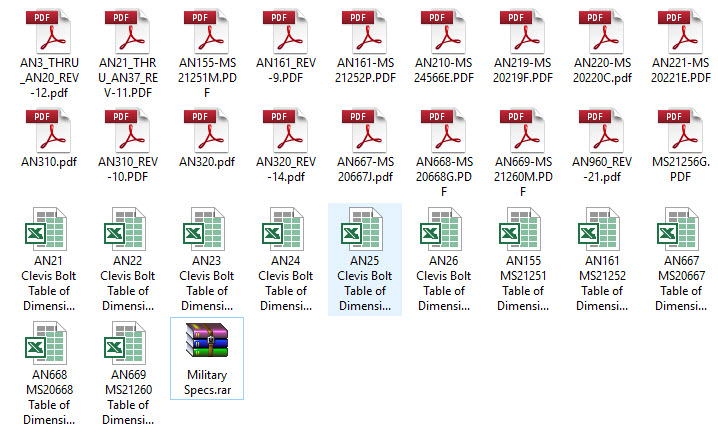
The complete list of known ordinate points for the B-25 B,C,D Fuselage, Wings and Empennage are now recorded in a set of excel spreadsheets. A few additional drawings (PDF and DWG) have been created to further clarify the main datum points for aligning the main assemblies and a 3d Autocad drawing of full assembly profiles.
- Fuselage: Frame Ordinates
- Fuselage Stringers: Ordinates
- Inner Wing: Ordinates
- Outer Wing: Ordinates
- Rudder: Ordinates
- Vertical Stab: Ordinates
- Horiz Stab: Ordinates
- Nacelle Firewall: Ordinates
All enquiries please contact me at HughTechnotes@gmail.com


 The full Ordinate/CAD dataset will literally save you 100’s of hours of tedious work and is available online.


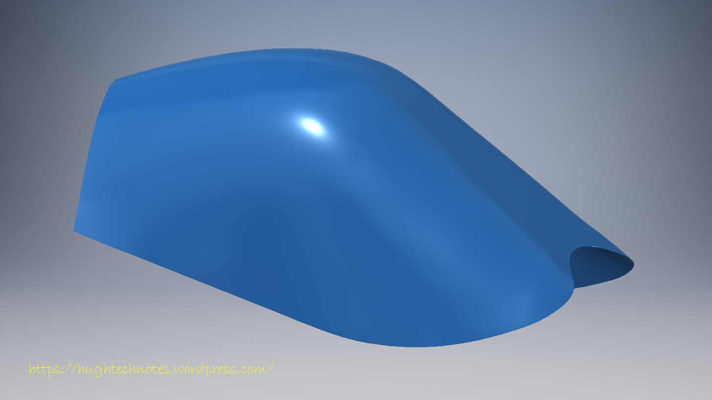

 I have managed to obtain a trial copy of the Inventor LT so I can now move ahead with this project. This first interpretation of the fuselage profiles is actually not bad at all. A few macro adjustments will be required to get the profiles correct, mainly due to the quality of the archive where roughly 10% of the values are very difficult to read.