NAA P-51 B/C/D Mustang
This is one of those projects that gets started and then for some reason gets put on the back-burner until now. One of the key reasons was due to the challenge of obtaining a good surface representation for the lower cowling for the P-51 B/C where I was having problems with the duct intake profile.
As usual I started with listing the ordinates in a spreadsheet and converting these to millimeters and extracting the X,Y.Z coordinates for further work in CAD.
I prefer to work in millimeters as I know that at so me stage the end profile may need micro adjustment which is so much easier to do using millimeter units.
This is a scrap view from the NAA drawing showing the ordinates table and the contours.
Thankfully for this part most of the ordinates were quite legible with only a few requiring interpolation; which would be done as a consequence of developing the data in CAD.
As it turns out there were a few orphaned ordinates that for some unknown reason did not align with the CAD developed surfaces; so these were simply ignored instead of trying to invent a purpose for them being there!
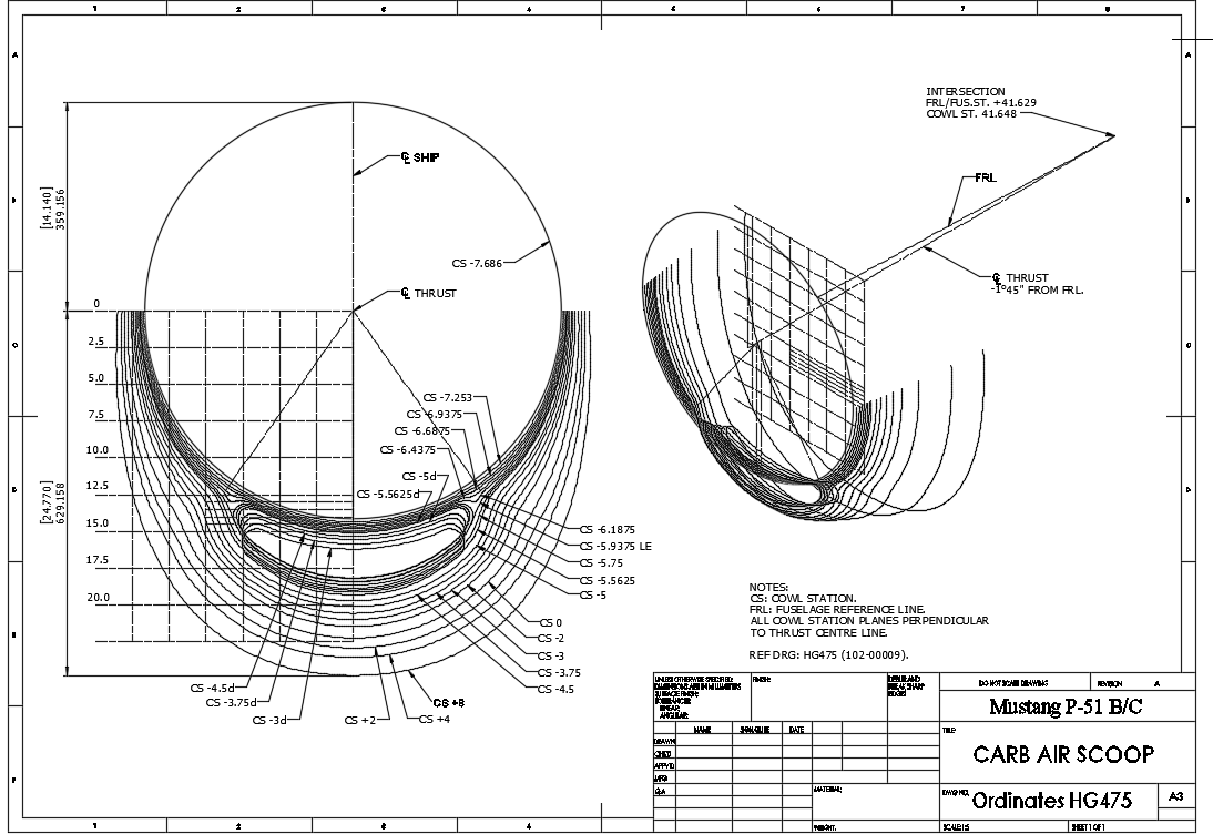 The drawing (right) shows the end result of transferring the spreadsheet data into a CAD product. This drawing is simply a record of the translation process and surmises the ordinates in relation to the Thrust line and Fuselage Reference line.
The main body of the cowling did not present any real problems but the intake duct portion did.
This area is less than 3 inches deep and is actually quite a complex surface; so any small deviation from exactness results in some crazy surface deformations. The original data tables are actually extremely good requiring only one small adjustment to get the result I was after…the trick was identifying which ordinates to use for the end profile and which ones we needed to check we have it done right.
After many (about a dozen) test developments of surface development and interrogation of the original data tables to ensure correct translations I eventually determined the correct ordinates and profiles to use to get this right.
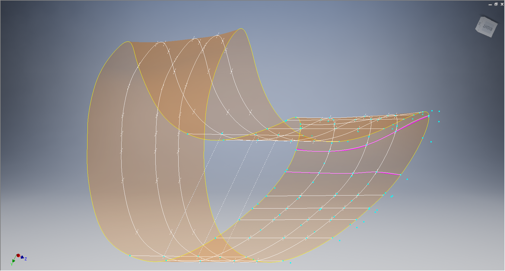
The resulting surface is based on the selected original ordinates with only one requiring micro adjust. In most cases the adjustment is simply an error in interpreting the sometimes indistinct values in the original data where a 6 could be an 8 or a 3 could be 5.
The 2 magenta coloured contours are generated profiles from a surface section cut overlayed on the ordinate controlled contours from the NAA tables which provides a check to ensure the surface conforms to the original design.
This surface will be converted to a T-Spline surface to facilitate final development.
It may be that this particular part does not warrant this level of exactness nor indeed the time expended in getting to this point. However it is a testament to the many fine designers of this era to be able to reproduce their work that was done to an extraordinary degree of accuracy.
Update Jan 2021: A comprehensive Ordinate/CAD package incorporating all known ordinate data points is now available for download. See this post for details.