Overview Ordinate Dimensional Studies

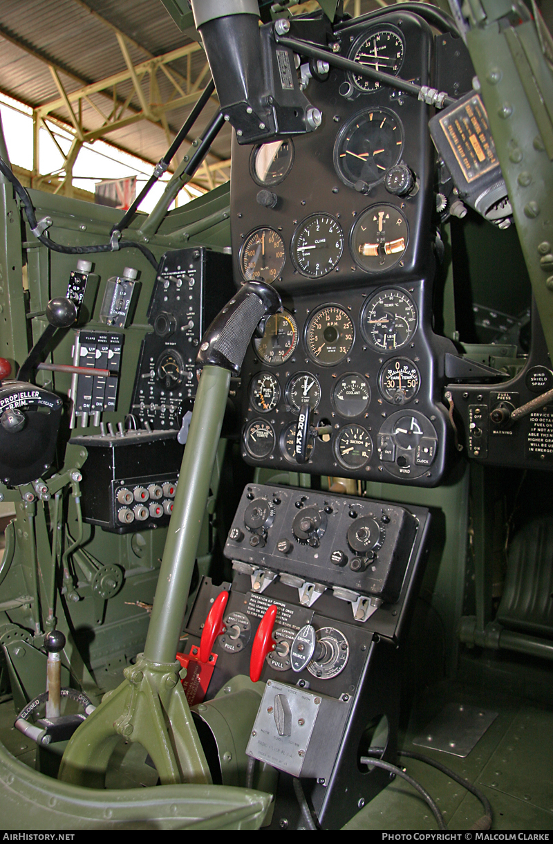
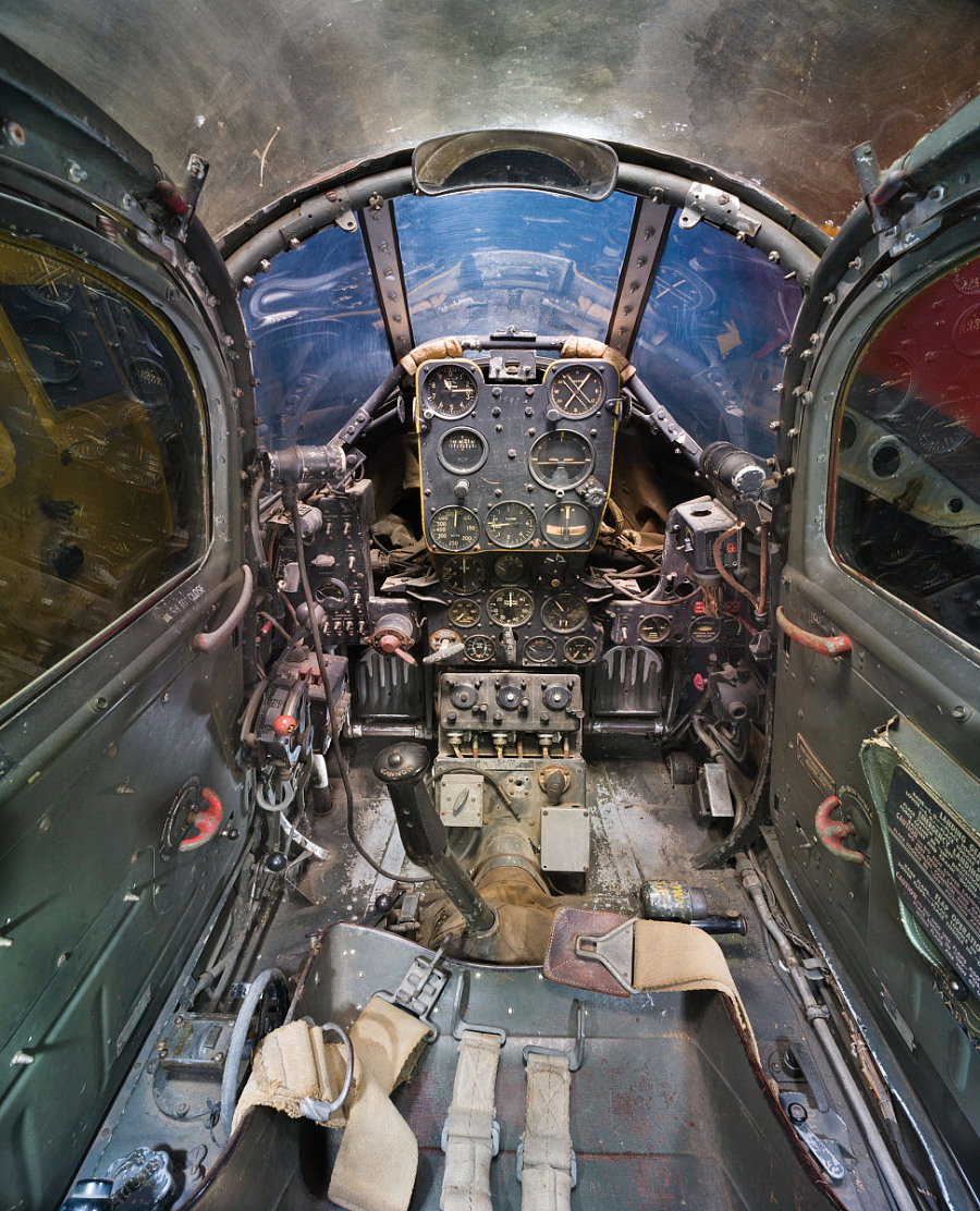
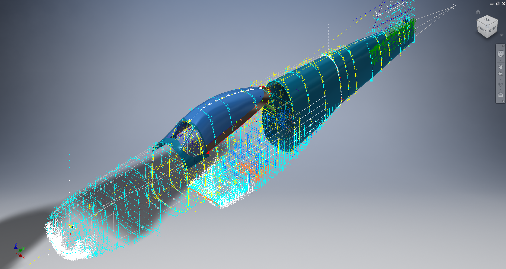
Overview Ordinate Dimensional Studies:

On the CAD/Blueprint resource page, I have compiled a list of Ordinate Dimensional studies for various aircraft. The purpose of these studies is to gather all known dimensional information in a format that can be easily transferred to any CAD system. Additionally, they serve as a dimensional check to verify the designer’s intent and assess the accuracy of data from different resources, including blueprints, manuals, and correspondence.

Let me give you an example:

I am currently updating the CAD/ordinate dataset for the Grumman Goose and have already identified a few anomalies in the empennage. This document includes the layout study for the elevator, and you will notice that, based on the blueprint dimensions, the trim tab is incorrectly positioned.

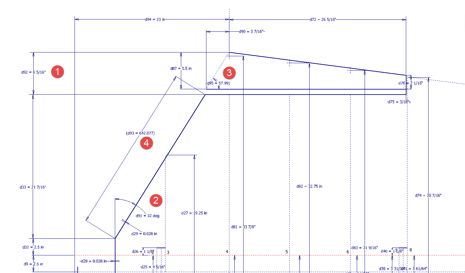
At first glance, it may seem that the dimension labeled “1” is incorrect, as it appears to be the catalyst that causes the trim tab to go out of alignment. However, when we consider the length of the diagonal line labeled “4,” which measures 642.07 mm (25.27 inches), we find a discrepancy with the blueprint that specifies this dimension as 25 inches. Additionally, this measurement does not align with the chord dimension for the rib labeled “2.” As it stands, the angle of the sloping line appears to match at 32 degrees for both the trim tab and the elevator.

This type of issue frequently arises when working from blueprints for any aircraft project. To address it, further research is required, which will involve cross-referencing all part and sub-assembly blueprints in the affected area, reviewing general arrangement layouts, and consulting relevant manuals. It is essential to understand the design intent in order to develop the most likely solution. I have even extracted key information from correspondence that was important for the P-51 Mustang.

Small dimensional discrepancies are common in these projects, not only due to converting inch dimensions to millimeters but also because of typographical errors on the blueprints themselves.

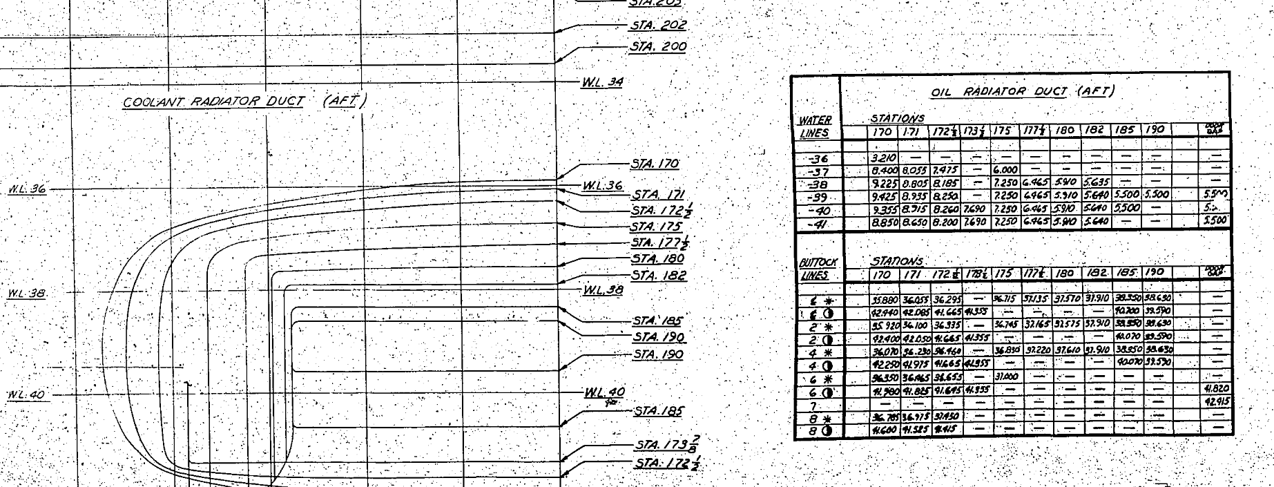
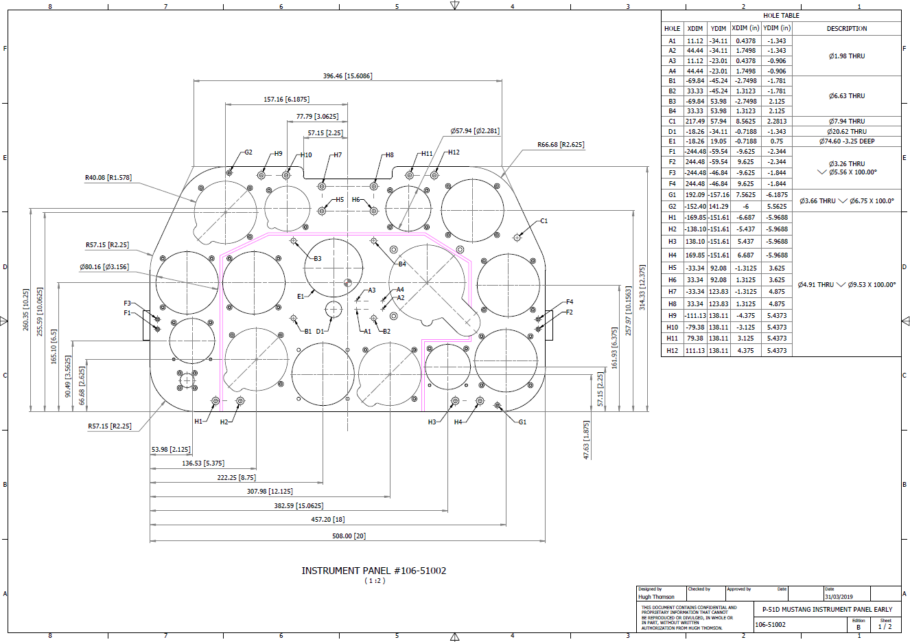
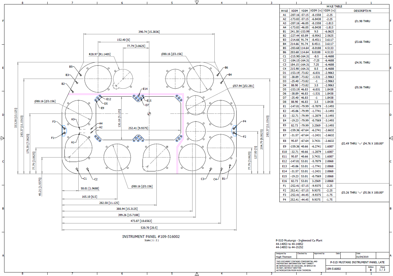
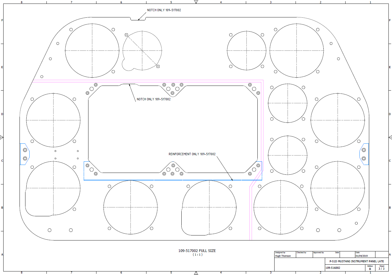
The screenshots of the Ordinate spreadsheets display the dimensional information for the Horizontal Stabilizer and the Rudder. Several dimensions are highlighted in red, indicating errors on the blueprints that have been corrected. The dimensions marked in gray represent the measured dimensions from the CAD model. This discrepancy arises from the inherent accuracy of the specified dimensions, which may only be precise to 1/32″. As a result, minor deviations can occur during the CAD development process. Understanding these differences requires careful consideration of all key layout dimensions and material thicknesses, as they all influence the final derived dimensions. Nothing is taken for granted.

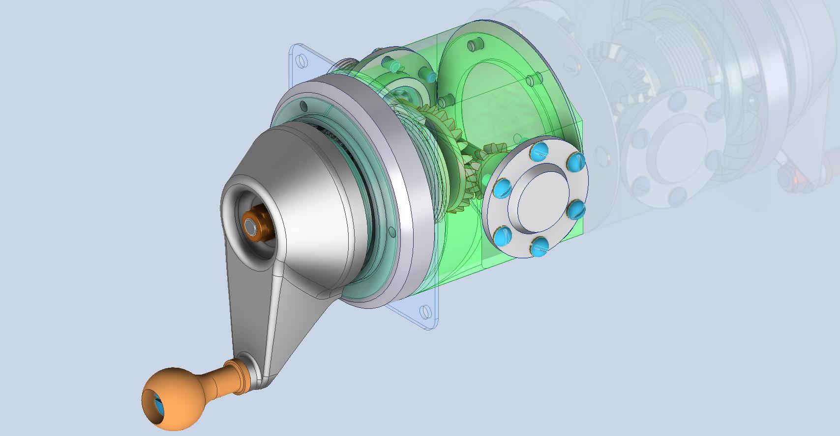
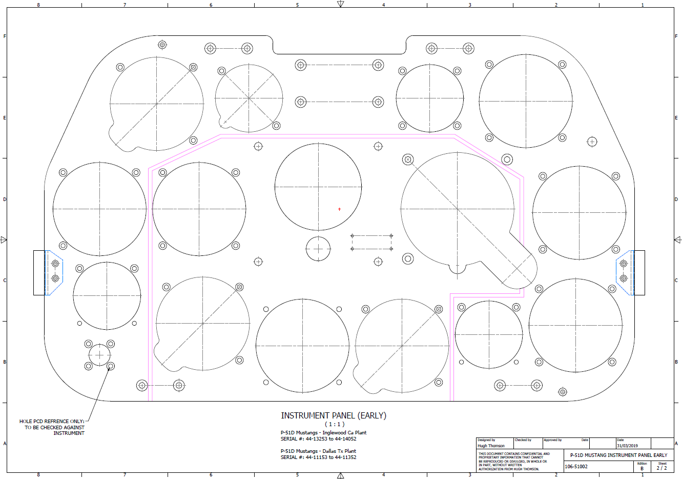
The CAD/Ordinate datasets compile all known dimensional information from various thoroughly researched sources, providing a comprehensive collection of data. This data is presented in editable spreadsheets, fully dimensioned drawings, and 2D/3D CAD drawings and models.

Elevator Layout Solution:

I have identified a solution regarding the layout dimensions. The dimension labeled as “1” is incorrect, but it is not the primary issue. Firstly, the Trim Tab has its own drawing #12530, which indicates that the overall length of the tab is 28.75″. This measurement is incorrect; it should be 29.75″. Additionally, other dimensions are also contributing factors.

In the bottom left corner, we find the specifications for the Hinge and Torque Tube, where two dimensions are marked with a tilde underscore to indicate that they are approximate. Generally, approximate dimensions are expected to be close to the actual measurements; however, that is not the case here. By adjusting the overall length of the Trim Tab along with modifying the approximate dimensions at the hinge torque, and also ensuring proper alignment with the known trailing edge, I have arrived at a workable and accurate solution.

Tech Tip: Using the Ordinate Spreadsheets:

I often get asked this and I have written about using the Ordinate spreadsheets before. Bumping it up to a more recent post, this one; I thought I would share a quick tip.

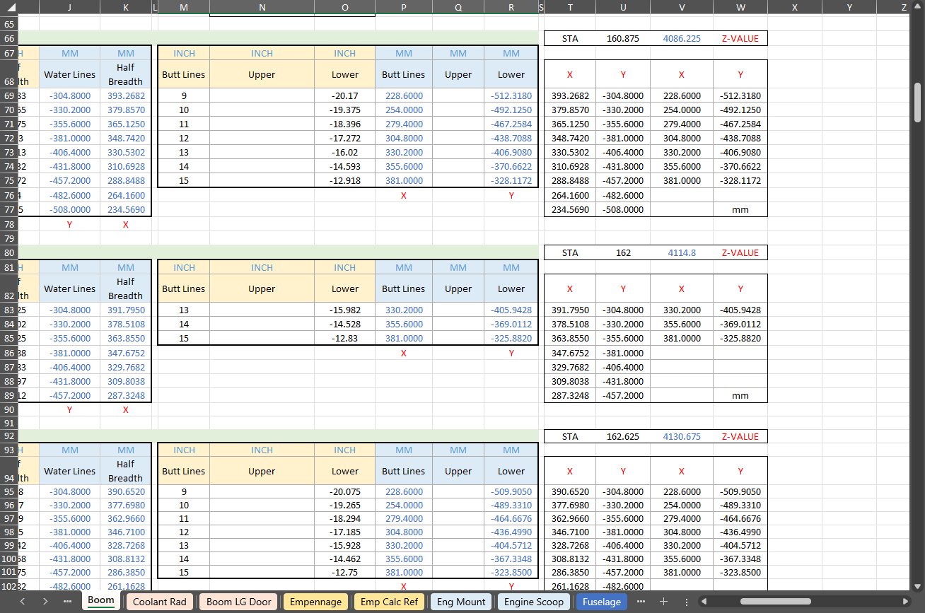
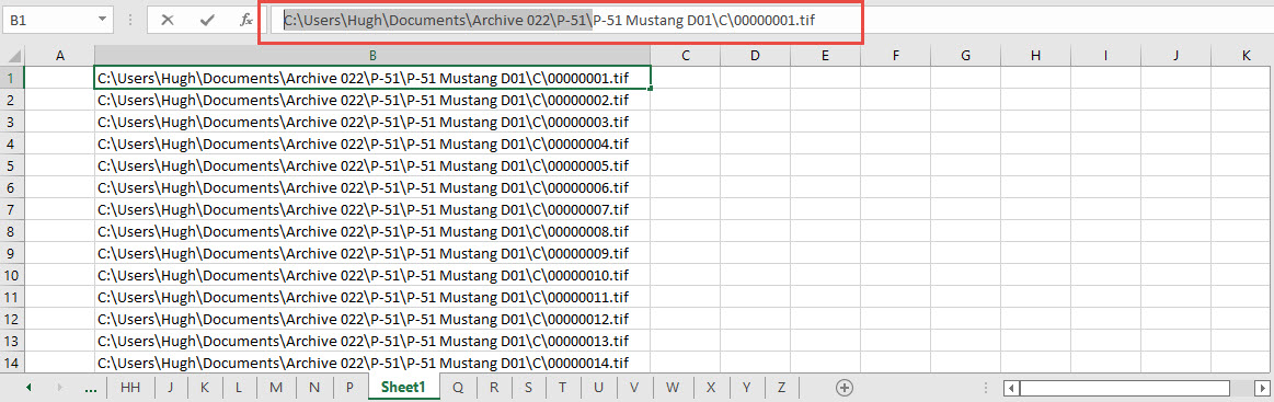
The Ordinate data spreadsheet is on the left, while the other is an empty spreadsheet that I use to paste data for a specific frame or rib that the CAD system can access. The empty spreadsheet just sits on my desktop, which makes it accessible.

Generally, the format of the data table is set out according to the original resource, which makes it easier to cross reference and check. This is not entirely ideal for CAD access as the X, Y coordinates are in rows and not in columns. The fix for that is easy, copy the data from the spreadsheet as required, select Paste Special in the destination spreadsheet making sure to select the “Values and Formats” and the “Transpose” options. The former ensures the data format remains the same and the purpose of the Transpose function is to convert data rows to columns. This gives us the data in X, Y columns ready for insert into the CAD system.

Note the “inch” header…I am using a millimetre template in my CAD system so I have to specify the unit of measure when I select from the first table. By the way, there is a second table that has all those values converted to millimeter anyway, so we could easily use that…in this case, you would not require a header row.

In other datasets, I have developed additional data tables in the spreadsheet, where I have transposed columns for the X, Y, and Z coordinates, such as those for the P-39.

I receive a lot of feedback from users about the spreadsheets, specifically regarding the time they save on projects since they do not have to manually input data themselves.

Technote: Inner Workings

Technote: Inner Workings:

Working on the controls and instruments for the P-39 spawned a plethora of questions about how these controls actually worked. So I endeavored to incorporate the inner workings in the Trim Tab Control CAD models. This was specifically to get a better understanding of how they work. This was not a mandated requirement. The initial work scope was replicating the external components for a static display P-39 restoration.

Often enough in museums and private collections, we only see the external controls. For many, this is all they want to see. But what if we also see the internal gears, pulleys, shafts, and bearings to understand how they operate? This is exactly where I now want to go with my future projects.

The Trim Tab controls for the Elevator, Rudder and Aileron are already modelled for the P-39 including the internal components. These dials and controls are currently being manufactured for the restoration project. The decision has now been made to incorporate the working mechanisms as functional replicas. This is great and will actually have some form of function, however, the mystery of operation still eludes the operator. I want to take this a step further and produce desktop models with Clearview casings so that the internals are visible. The exact method is still under review. It will mainly comprise 3D printing techniques for the main components attached to perspex casings.

The dials for all 3 controls are similar with the Rudder and Aileron dials operated by a control knob (not shown) and the Elevator Tab controlled by a wheel as shown. At the base of each control dial there is a sprocket for a short Roller Chain which in turn is attached to operating cables. Out of curiosity I decided to have a look at other aircraft to see how alternative mechanisms were developed for the P-51 and the FM2.

For the P-51 the Trim tab controls are comparable in their operation with the internal gearing arrangements but differ slightly in design.

The dials for the Aileron, Elevator and Rudder are all similar to the CAD model shown. The Elevator and Rudder have cable drums attached to a long shaft for direct cable operation whilst the Aileron has a chain sprocket similar to the P-39 Trim Tab controls.

The plan for the P-51 is to fully model all the components in the assembly shown, complete with cables and chains to simulate operation.

A small point of interest; the various aircraft designed by the same manufacturer often share common parts; for example the NAA drawings for the B-25 share the same Trim Tab control knobs as the P-51 and listed accordingly. For some reason, the P-51 drawings do not reciprocate.

If you can’t find drawings for a particular part, check collections for other aircraft by the same manufacturer. Occasionally, this can be worthwhile. Similarly, with Grumman, many parts were shared with the FM2 and the Grumman Goose.

The above model is the FM2 Elevator Trim tab control, the main body of which is typical for the Aileron and Rudder on Grumman drawing 13690. The Grumman Goose has similar controls shown on the Grumman Drawing 13693. Shared components across the various aircraft are listed on the Grumman FM2 drawings.

This Trim Tab control for the FM2 is probably the most complex I have studied so far…requiring very fine manufacturing tolerances. I am not entirely sure yet how this works as there is a complex array of tabbed washers that act as stops for the dial in both directions; it is unclear at this stage how they should be configured…I will get it worked out in due course.

A lot of work to do on these projects which will definitely keep me busy through 2025.

Technote: 3d Modeling to Clarify Assemblies

Technote: 3d Modeling to Clarify Assemblies

Interspersed throughout this blog are many examples of Technotes describing techniques and problem-solving primarily for 3d CAD modeling. Many of the part examples shown are actually created to address another major issue with Assemblies.

It is not uncommon for the assembly drawings to be either unclear or simply void of key information that would help establish relationships between sub-assemblies or parts. In many examples, it is simply that the reproduction of the microfilm prints is not sufficiently clear to comprehend what is going on, otherwise the omission of basic dimensional relationships.

For the P-51 Mustang, I fully developed the rear Landing Gear mechanisms to clarify what the heck was going on as the NAA Assembly drawings details were obscured.

It is too often the case that general assembly drawings tend to be nothing more than an illustrated parts list with few key dimensions that define locations or relationships between the individual parts. This is also true for many of the sub-assemblies. For the P-51 Tailwheel sub-assemblies, I also developed 2D detail drawings showing key dimensions and parts lists. Ideally, I would have developed presentation drawings showing the exploded views of each of these assemblies to provide further clarification…perhaps a project for the future.

In the case of the P-38 Lightning, I have developed the Landing Gear assemblies to check the ordinate dimensions… which by the way are good. I now have the Coolant Radiator assembly which was again developed to check ordinate data but also for the same reasons as I did the models for the P-51 Tailwheel.

Typically the general assembly pictorially shows the sub-assemblies without any key dimensional information to define the location or part relationships and similarly, the sub-assembly for the clamp is not that much better. This is important stuff as occasionally they are the only reference material we have to help define ordinate data that is missing from the archive blueprints.

The Coolant Radiator is compromised by wrong dimensions as well…the top clamp cover, for example, had dimensions for the connection to the rod with the part drawing showing conflicting locations for different views of the same part.

The problem here is the connecting bracket item 224045 cannot possibly be 1″ from the edge of the cover plate whilst the overall dimension of 6 7/16″ prevails. I initially had located that bracket at 1 inch which seemed to be correct at the time because it fitted the part profile but when I introduced this into the assembly drawing it would not correctly align with the radiator. However, when I revised this using the 6 7/16 inch dimension it worked. That connecting part also caused more problems because the face of the part is machined 1/64″ which is not taken into account when positioning the part in the assembly.

Accumulatively this resulted in the overall width of the clamp assembly being smaller than it should be. This only came to light when I modeled the 234183 almost inconspicuous part as the stated dimension of 9.25″ did not fit with my initial layout..my first thought was this may just be an oversight but when I tried to align the main support frame (in gray) it did not align correctly. I went through everything and realized that the machined face of the corner parts connecting to the rod as shown may not have been taken into account and when removed the alignment was better and the 9.25-inch dimension on the strap was now correct. I am convinced that there should be spacers/washers between those connecting parts but this is not apparent on the assembly drawings. There remains a small discrepancy of 0.8mm which I am unable to account for….as this mainly relates to a clamp mechanism that will be compressed on assembly it was probably not deemed important but when you are trying to establish baseline dimensions it is actually very important.

The Part catalogs generally are your first port of call when developing these assemblies but they do not contain the key dimensions you need so these 3d CAD models are essential to achieve clarity. Incidentally, while we are talking about part catalogs it is important to understand what parts belong to which version of the aircraft. For the P-38 Lightning, the first few pages list the version and serial numbers which in turn are listed elsewhere where a Usage code is assigned. In this case the “e” is essentially the P-38H and the “bv” is the P-38J. The P-38 Part catalogs tend to show the version variations on one page; which can be really daunting; whereas others may show the version differences on separate pages…so you have to be attentive.

As I mentioned at the beginning of this article the main purpose of these assembly models is to achieve clarity and to check dimensional relationships. I think this is very important stuff that would certainly benefit from exploded views in conjunction with clear assembly 2d drawings.

As usual, get in touch if you can help support my work. hughtechnotes@gmail.com

Technote: P-51 Mustang Drawing Register Updated

Technote: P-51 Mustang Drawing Register Updated

There seems to be a theme developing here…following on from my efforts to organise the chaos of large blueprint collections I endeavoured to continue my efforts with a long-overdue update to the P-51 Drawing register.

The P-39 Airacobra register was a breeze by comparison to this P-51. That was only a matter of 4-5 hours of work which was aided by the fact the drawing filenames were already fully described…all I had to do was add the Film Index numbers alongside the filenames. The P-51 on the other hand only had obscure filenames that were somewhat inconsistent…which meant this exercise ran into a few days. Occasionally my enthusiasm tends to thwart common sense!

Getting back to the P-51 Drawing register. The update is now inclusive of hyperlinks contained within the excel spreadsheets that will open the associated drawing. This is a huge step forward in managing and working with such a large archive and though it took ages it is a major improvement.

As you can see LINKS have been added to the right column (J) with hyperlinks recorded in column L. This column is hidden but can easily be viewed by using the option to UNHIDE. The Film Index reference is the actual microfilm reference hard coded onto the original film which differs from the actual filename that was generated when the film was scanned.

I should note at this stage that a number of folders in the archive will require renaming as Excel does not like #hashtags in naming conventions. The download section includes a word document describing the file-naming convention.

The hyperlinks are plain text entries originally copied from the development process that utilised the Vlookup function referencing a separate spreadsheet. I had considered including the separate spreadsheet in the download section but I think that just over-complicates things. About that development process!! It may be prudent to provide a quick overview of how things were developed.

The Development Process (briefly)

The initial process was to extract the filenames from Windows Explorer and deposit those records into a separate spreadsheet. The way to do this is to select all the files in the folder and click the Copy Path option in the windows explore toolbar.

Paste this into a spreadsheet and then remove the first part of the path (highlighted) so the location parameters now become a relative path to the root folder. This was done using the Replace (CTRL+H) function by copying the highlighted portion and applying a null space to all of the records.

This is now the actual hyperlink path which we need to associate with the actual Film Index. As mentioned above the Film Index is recorded on the scanned images and therefore a fair amount of manual intervention is required to record this value in column A. Using the Vlookup function necessitates that we use the column on the left for the value sought to return the value on the right. As you can see from the many tabs on this spreadsheet I filtered out all the filenames from every folder and then proceeded to populate the column in each case with the Film Index number…that drove me nuts!

There are several ways of accessing the values using Index and Match or even Indirect in conjunction with Vlookup…but we shall stick with the simple option of using Vlookup.

The Vlookup function asks for an initial lookup value; in this case “I10” then it asks for the corresponding Table Array; essentially the array of data from which to search. In this example, the array is defined as the values from the spreadsheet called “FILELIST” Tab “A” from cell A1 to B1043. The “2” refers to the column from which to extract the value you are seeking…which refers to the second column. “False” is for an exact match to the value in I10.

The Link is simply the =HYPERLINK function referencing the value in column K with a text value defining the label “LINK”.

You can combine the HYPERLINK function with the VLOOKUP in one formula like this…though it does take a fraction longer for the link to open.

That’s the basics of how this was done. using Indirect in conjunction with Vlookup enables you to search for the tab designation from a tab list that would look through the entire spreadsheet for the sought value. I didn’t think this was necessary for this exercise.

I mentioned the folder name changes that are required for this to work. The 3 main folders should now be changed to P-51 Mustang D01, D02 and D03.

The updated drawing registers will be available for download this evening so watch this space for an update.

As usual, the spreadsheets are fully editable so you can adapt the data to suit your own requirements. I would note that the Vlookup formulae are not embedded within these drawing registers as the hyperlinks are just copied text values and not live links. The recordset “FILELIST” is not available for download but if you would like a copy to play around with Vlookup or similar then please just drop me a line.

Update (earlier than expected)

The updated P-51 Mustang Drawing Registers are now online and available for download. Please let me know any comments or feedback.

This folder also includes the Aviation Manufacturers Standard Parts file which I am trying to consolidate as they tend to pertain to more than one aircraft.

Comments or feedback as usual to hughtechnotes@gmail.com

P-51D Mustang: 3D Instrument Panels

P-51D Mustang: 3D Instrument Panels: Updated 11 June 2022

P-51 B and D Instrumentation Panels are now available online as a separate package. This package includes all below noted Instrumentation Panels 3D CAD models in STP, STL and 3D DWG formats with associated dimensioned 2D drawings and PDFs. Note the hole positions are listed in a tabulated form on the drawings which can be extracted for CNC work.

Also included is a copy of the original NAA instrumentation drawings for reference.

Update 20th June 2022: All Instrument panels now also include the Parasolid X_T format. The complete package is available for download, get in touch at hughtechnotes@gmail.com.

Early Version P51D: 106-51002

Later Versions: 109-516002, 109-517002

Update 15th Feb 2022

For P-51B Mustang: 97-51002

3D Model Views:

For further information drop me a line at hughtechnotes@gmail.com.

P-51D Mustang – Instrumentation Panel

P-51D Mustang – Instrumentation Panel

I have recently been working on updates to the Ordinate and Cad package (as noted in the previous posting) and also developing the Instrumentation panel assemblies for the P-51D Mustang.

What started out as a mere curiosity is actually turning out to be a fairly intensive project requiring a lot of research.

For the P-51D there are at least 4 variations on the main instrumentation panel for the early and late models. The U-shaped Support frame has 4 variations and just as many for the lower instruments panel set at 20 degrees to the main panel. It is important to get the correct combination of components for the various model numbers which is where a lot of my time is spent on the research.

Part of that research is, of course, getting the label text just right which is where I encountered a lot of frustration. The generic text font used on the Mustang and many of the contemporary aircraft at that time was the MS-33558. There is a TTF font available online for download but the design is not very good with problems of self-intersecting edges and spacing definition.

Military-Standard-MS33558ASGUsing this font in CAD systems will result in problems with embossing or extruding.

Typically I had to find out why, so I downloaded a copy of Fontforge to analyze the characters and identify the problems. Most of the characters are fine but there are at least 7 that have intersecting line problems. However, due to the nature of the font construction process, it is very difficult to identify the problem areas and thereby to devise a solution.

I spent a few hours looking into this but font development is a relatively new procedure for me and I did not achieve any satisfactory results. This I think needs an expert touch. I appreciate the work that was done in developing this TTF but please whoever designed it just a bit more attention to detail would have saved me a lot of work.

In the interim, I decided to use the closest font I could find on my system which was a default SolidEdge font that is similar in style. I had SolidEdge as a trial program a while back and thankfully it left the fonts behind when I uninstalled it.

Another small point worth noting is the color of the label text. The images above show the early P-51D version arrangement and you will notice in the bottom left corner of the first image is a selection of text in red. It is “EMERGENCY” with an associated note. The drawing states that this is RED on a black background but many of the photos I have seen of this particular version show the text in white. So the question is did NAA change this at some stage or is it just down to restorers’ preference?

NAA P-51D: Master Lines Plan

NAA P-51D Mustang: Master Lines Plan

The P-51D project is progressing well with further developments on the fuselage frame profiles. I now have a comprehensive Master Lines Plan incorporating additional information obtained from mathematical analysis, drawings, reference documentation and geometric developments. I have updated and remodeled the underside Oil Cooler Air intakes, canopy, windshield, rear fuselage and fuselage tail-end. As part of the remodel the groups of ordinates for each frame for the Oil Radiator Duct, Coolant radiator Duct and Removable Scoop are now contained on their own respective work-planes. This will make it much easier to micro manage the final mold lines.

Fuselage Master Lines Plan (P-51D overlaid on P-51 B/C):

2017-07-01_14-32-09

Test Lofts and developments:

2017-07-01_14-30-24

Front Views (note the Canopy Profile update from the previous article):


A month ago I was not sure how much could be achieved given the limited amount of information at hand but with due diligence and detailed research, it is quite amazing what can be accomplished.

With this template, it is now technically possible to accurately develop a CAD model for the entire fuselage structure and mechanical components for the P-51D, which would be great; but I often wonder what the value of such an undertaking would achieve, other than being a darn interesting thing to do and a test of CAD modeling skills.

Having achieved this significant milestone the time is right to conclude the work on the Mustang P-51D and P-51 B/C projects. I may continue with the P-39 project but as always I am keen to explore the options for the more obscure extinct aircraft as described in Operation Ark.

2017-07-01_00-15-20

If you are planning on developing your own Master Lines plan a good place to start would be with the 1000’s of ordinates points cataloged and recorded on the spreadsheets here: Mustang P-51B/C Ordinates which also includes the wing ordinates for the P-51D and vertical stabilizer.

NAA P-51D Mustang: Using Ordinate Data

NAA P-51 Mustang: Using Ordinate Data Spreadsheets

A question arose during a telecon today about using the Ordinate Spreadsheets for Cad and Modelling.

2018-11-30_08-40-04

Typically for the fuselage and cowlings, the spreadsheets are set out as above. The top section replicates the layout of the original manufacturer’s drawings specifically to allow traceability for verification purposes. The section below, bordered in blue is the concatenated values from the top table in a format such that the values represent the actual X,Y,Z coordinates for each point.

2017-05-23_21-47-42For use in Cad systems like Autocad, it is recommended to collate these in a TXT file by simply copying and pasting.

Once collated open Autocad, select the Multiple Point feature and cut and paste the entire contents of the TXT file onto the command line which in turn will import the values as points.

For other CAD systems like Inventor the preferred format is an excel spreadsheet with 3 column headers X, Y and Z.

All we have to do is to open this same TXT file from Excel as a comma delimited file, check the options presented in the opening dialogue to ensure correct formatting and save the file as an XLS. Remember to label the first row as X,Y and Z.

2017-05-23_22-06-55

When you start a sketch in Inventor there is a feature on the toolbar to import Excel data. When you import the data there are a few self-explanatory options.

2017-05-23_22-12-58

There are of course many ways of doing this and it will vary according to what CAD system you use. Importing all X, Y, Z points in a 3D sketch, for example, will align the ordinates with the current UCS, which in some cases may not be desirable. The Z value is the Frame or Station location relative to the aircraft datum, which essentially translates to being the work plane location. The X, Y values are typically the sketch coordinates normal to the work plane.

If you are working on a 2d sketch and importing the set of points as X, Y, Z values; Inventor will only import the respective X,Y values and ignore the Z value, in fact, it will notify you that it is doing this.

Update: July 2018

The ordinate spreadsheets now have an additional page that compiles the ordinates for each frame with the X,Y,Z components listed separately. This makes it easier to manage the ordinates depending on what CAD system you are importing to.

2018-07-31_23-24-09

If you require any further information then please drop me a line.

NAA P-51D Mustang: Wing Ordinate Rev

NAA P-51D & B/C Mustang: Wing Ordinate Major Update:

Thanks to Roland Hallam, I am now in receipt of new verifiable information that has prompted a return to the P51 project and a major update to the wing ordinate data sheets.

2017-05-21_15-46-57

Many of the blanks have now been filled in and new additional information added. The above image is a snapshot of the work in progress. The groups highlighted in blue are checked verified dimensions, the red values are those that have changed and those areas remaining in white have prompted an interesting conclusion. Up until now, it was presumed that the wing profiles for the P51D and P51C were the same with the exception of the wing root, however, closer inspection would now suggest that a few rib locations are also slightly different which requires further investigation.

I am still working through the new information and dissecting what is relevant to the P-51D and the P-51B/C variants. This will probably take me a while to evaluate but I am confident that this will result in the most comprehensive dataset yet compiled for the P-51 wings.

I had not expected to return to the P51 project at this time but I’m sure you will agree this is an exciting development.

Mustang P-51 B/C Ordinates

Mustang P-51 B/C and P-51 D Ordinates:

P-51BC Layout

I have had a number of requests for the ordinate spreadsheets I developed for the Mustang P-51 B/C and D fuselage, cowl, cooler and air intakes, so I have decided to make them available to all; which could save you considerable time and effort.

The ordinates are listed on 10 separate Excel workbooks with 18 spreadsheets for all known ordinates from manufacturers data. The ordinate listings are in both mm and inches with the X,Y,Z coordinates extrapolated from this data-set for ease of transferring to a suitable CAD system. The total points listed are literally thousands.

P-51 D Layout
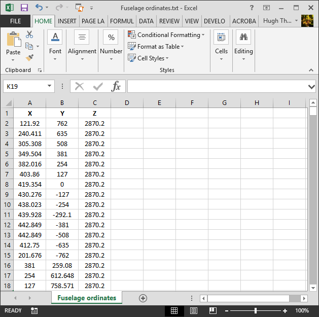
102-00005: Fuselage (BC main)
102-00006: Fuselage (forward to cowl)
102-00007: Removable Scoop (fuselage, Int and Ext)
102-00008: Coolant Radiator Duct (Aft Section)
102-00008: Coolant Radiator Duct (Fwd Section)
102-00008: Oil Radiator Duct (Aft)
102-00009: Carb Air Scoop (Cowl)
106-00006: Wing (P-51D)
73-00006: Wing (P-51BC)
 
+ Autocad DWG Fuselage Frame & Wing Profiles P-51 B/C and P-51D (ref only)
NAA Master Dimensions Report (wings, fuselage, landing gear).
Include scans of original source documents for reference.
 
The spreadsheets are not locked or protected so you can manipulate the core data to suit your own applications.
The P-51D fuselage profiles are reference only due to being mathematically generated based on original NAA methods and thus are not verified.

This represents a huge number of hours worked, meticulously listing each ordinate individually and then creating cad drawings to check the ordinates and derive the ordinates that are unclear on the manufacturers’ drawings.

2016-06-04_23-33-26

The ordinates for the P-51D wings comprises 2 sheets; the first listing the tabulated data as per the original manufacturer drawing and the second extrapolated to compile the X,Y,Z coordinates for input into CAD.

P-51D WING ORDINATE

P-51 Wing Profiles

Update 20 Aug 2019:

The spreadsheets now include the OLEO undercarriage and general tidy up of datasheets for consistency. Now probably the most comprehensive and complete dimensional study of the P-51 B/C and D. 2018-09-20_22-45-40

Horizontal Stabiliser and Fillet Ordinates layout:

Mustang P-51 BC

Sample data for P–51B/C and P-51D;

For further details see this more descriptive post or send me an email to HughTechnotes@gmail.com