Technote: P-38 Lightning Engine Cowl:
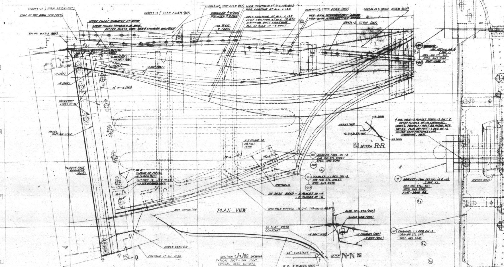
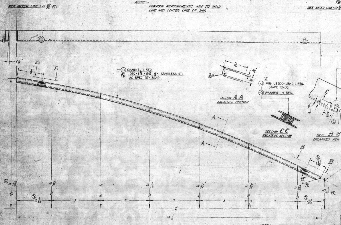
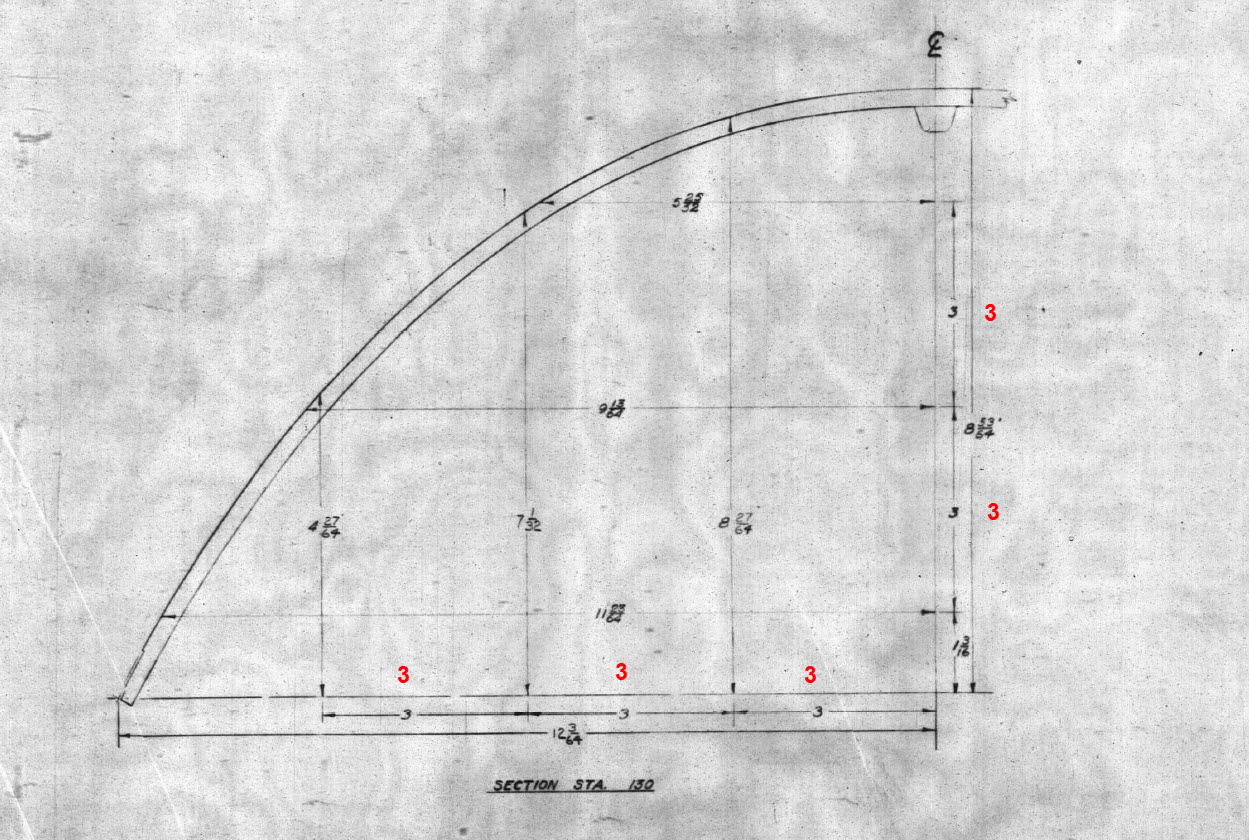
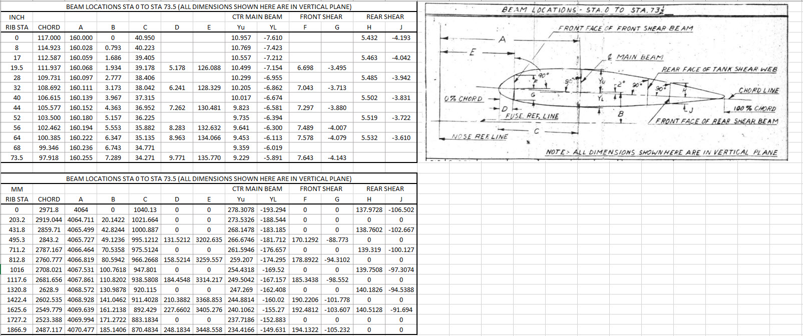
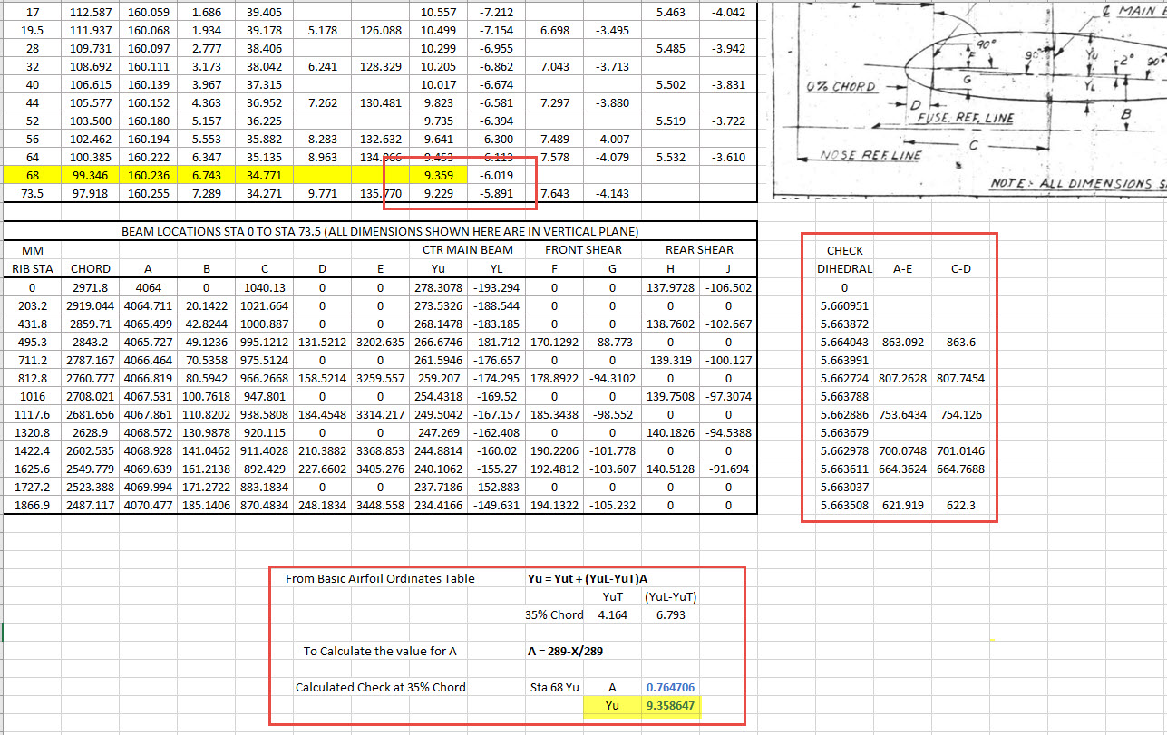
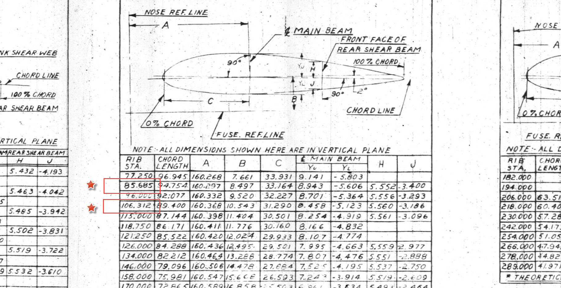
Yet another challenging aspect of the P-38 Lightning is the Engine Cowls for the P-38J and earlier variants. As before with the Coolant Rad Scoop, there are very few ordinate dimensions so this will require a similar workflow by developing what we do know to help determine what we need to know.
Part of this development includes the Shroud Air Intake Scoop which will provide some key data for determining a partial profile for the top section of the cowl.


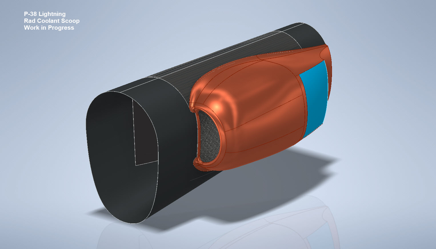
The engine cowl above is for the P-38J, I also have another work in progress for the earlier variants. Common to both forms is the Shroud Air Intake which is the main subject of this article. As per normal practice, I tend to first develop all the sketch profiles according to the drawing information…this is not always ideal for the CAD modeling environment but it is important reference material to ensure the final model is compliant.
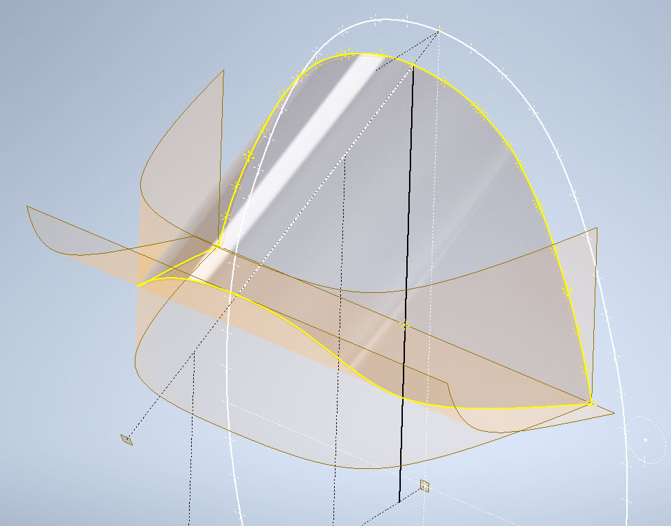
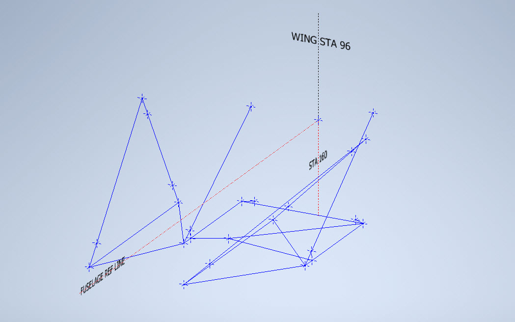
The sections described in the drawing show a gradual curve intersecting arcs that form the scoop…early on I determined that these will need to be separate sketches as they will be modeled separately and then combined. The first arc section is important for sweeping the scoop duct and then of course building the profiles of the leading edge, so this was actually created as a full circle. The remaining profiles are retained as arcs.


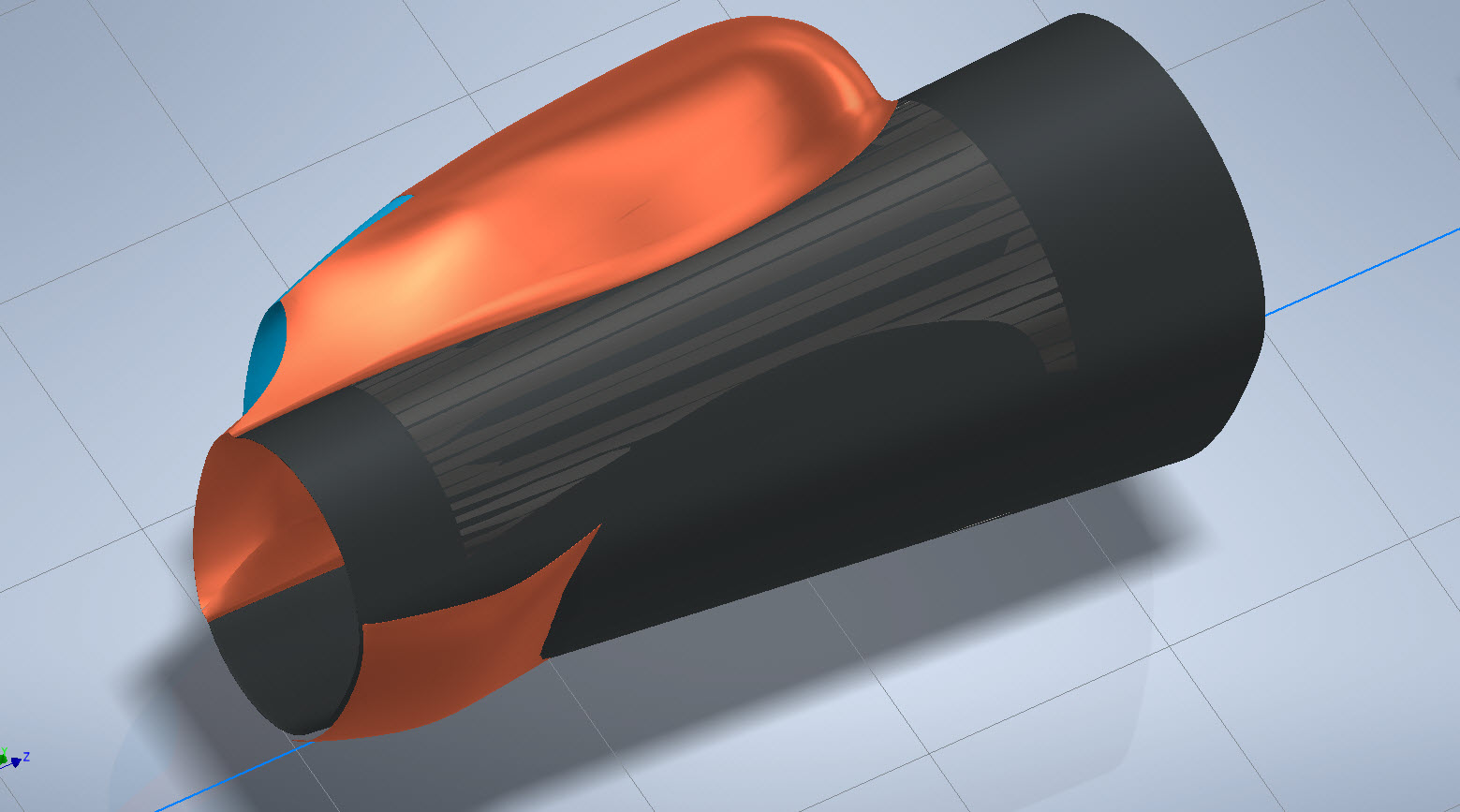
This profile is a swept feature using the centreline (1) as the guide curve making sure that the orientation is set to Fixed and not Follow Path. All the arcs are set perpendicular to each other so it is important to make sure the swept profile follows this alignment.
Another important consideration for making the leading edge a full circle path is when building the actual leading edge. I elected to build sketch profiles at each of the circle quadrants to account for the variations in the curved swept surface. The edge profile actually extends inside to form a lip which I offset from the main surface by 0.1mm… sometimes if the surfaces are coincident this causes problems with later editing.


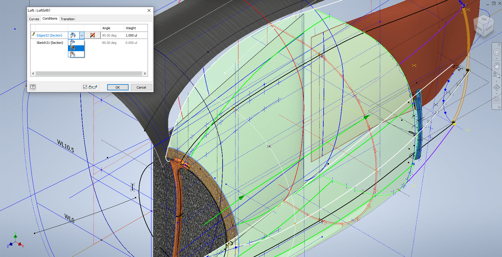
That worked rather well and gave me a smooth curved leading edge when lofted. A quick point to note is the loft does not do circular paths so the profile at D was duplicated and selected separately to complete the full circle.
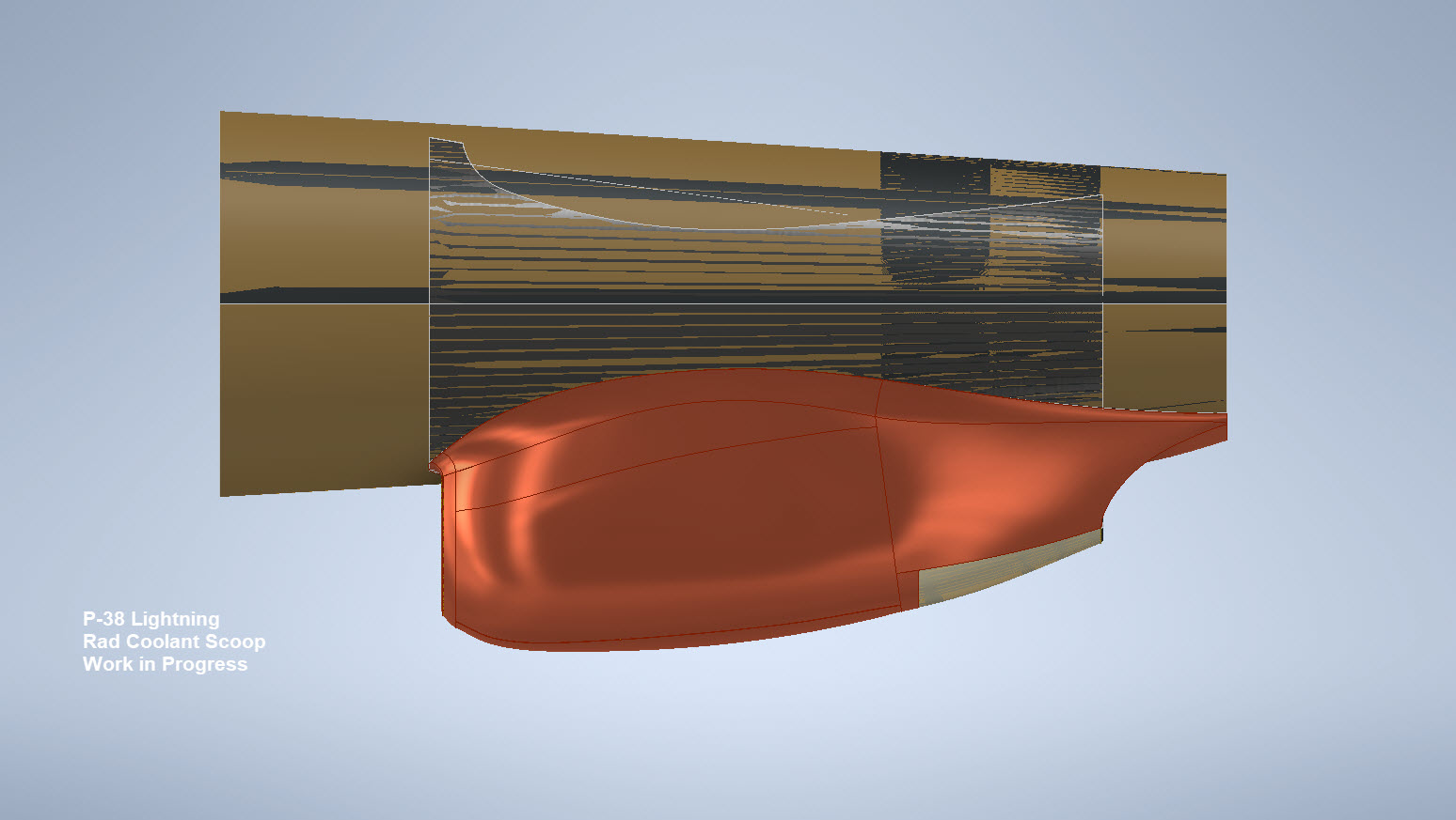
The second image above is the fillet applied to the stitched surfaces of the scoop main body and the curved plate. This is a variable filler as I wanted to control the eventual curvature around the leading edge. Regardless of how careful I was to ensure perfect tangency at the leading edge, sometimes this is not always possible and micro variations can result in a slight imperfection which prevents the edge selection continuity for applying the variable fillet.
So what I did was select the edges as separate sections within the same command which you can see at E, F, and G. To define each of the edges you first select the edge from the top panel and then adjust the variables in the panel below. By doing this within one command Inventor will adjust the finished fillet to be continuous along all 3 sections.
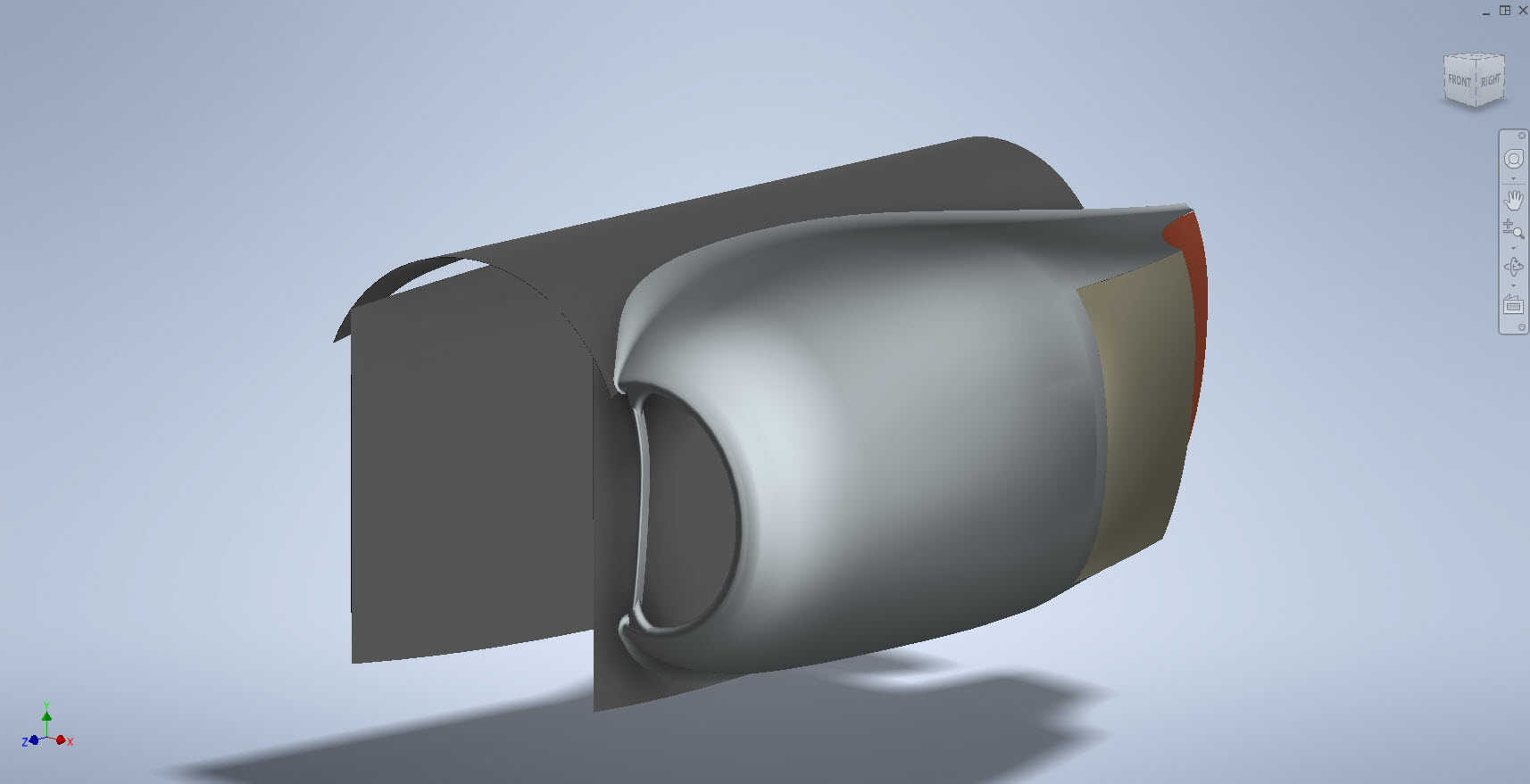
The final model is rather good and very accurate. The key thing is to think ahead as to how you will model these objects from the outset so it is well worth taking your time to get this right.


Update 28th Oct 2022:
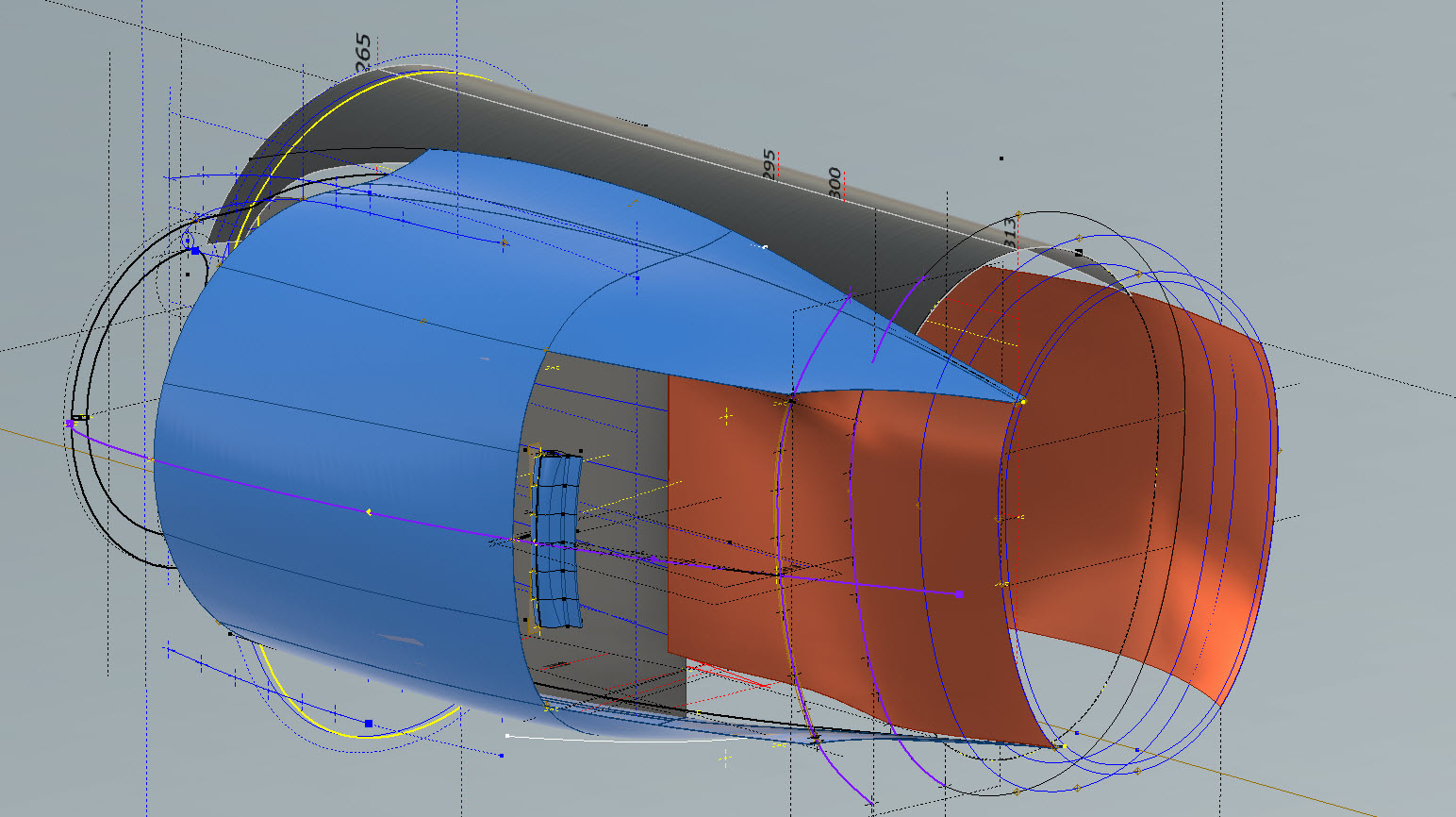
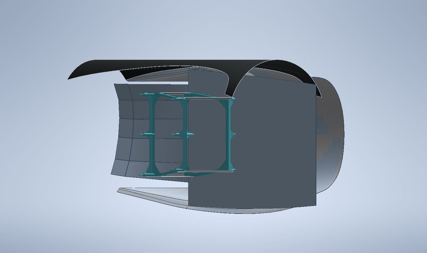
Just about finished with the P-38H Engine Nacelle…just a few items to add.


Just to give you some idea of the complexity of the underlying geometry: P-38H and P-38J Overlaid…

Update 6th Nov 2022:
This is the updated version of the Left-Hand boom on the P-38H Lightning.

.