North American P-51 Mustang: Air Scoop

North American P-51 Mustang: Air Scoop

Working with ordinates from these archive drawings can be a very time intensive operation. To give some idea of the content of this work I have just started working through the vast amounts of ordinate data for the Air Scoop and Oil Cooler.

2015-06-04_12-23-12 
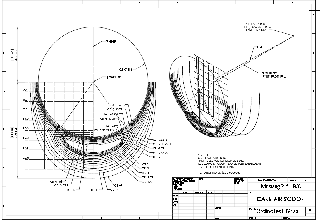
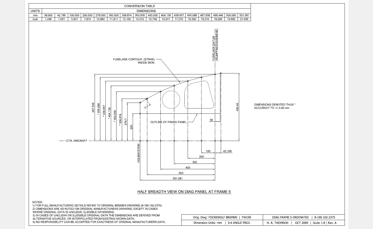
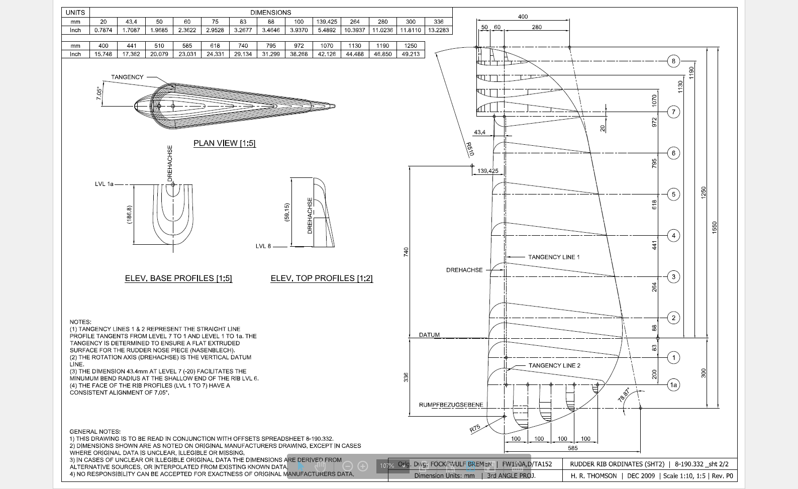
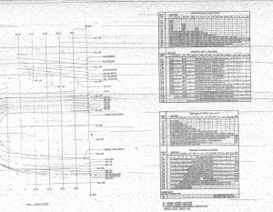
This is a scrap view of the original NAA drawings showing the main ordinates for the Air Scoop.

This drawing shows 2 tables, one of which is the listing for the external contours and the other the internal contours.

The external ordinates comprises a total of 664 points and the internal ordinates comprise a total of 928 ordinate points.

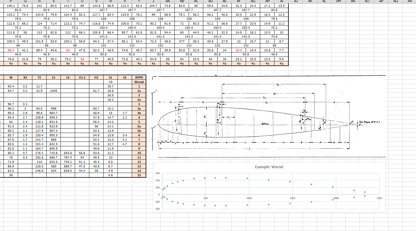
Each point is manually entered into a spreadsheet which lists the Inch dimensions and then converted to Millimeter dimensions.  The data has 3 values for the Station location, the Waterline (value along a horizontal axis relative to the ship ctr line at set intervals) and the Buttock line (value along a vertical axis relative to Frame Ref Line ).

2015-06-04_10-19-41       2015-06-04_10-17-50

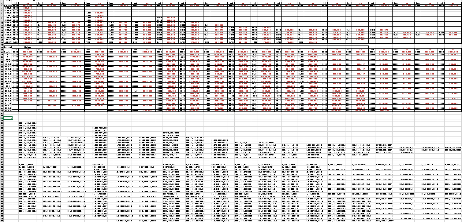
These values are then processed using the concatenate function in Excel to extrapolate the required X,Y,Z coordinates.

The points are then grouped and imported into Autocad to derive a point cloud.

2015-06-04_16-57-59 2015-06-04_11-04-09

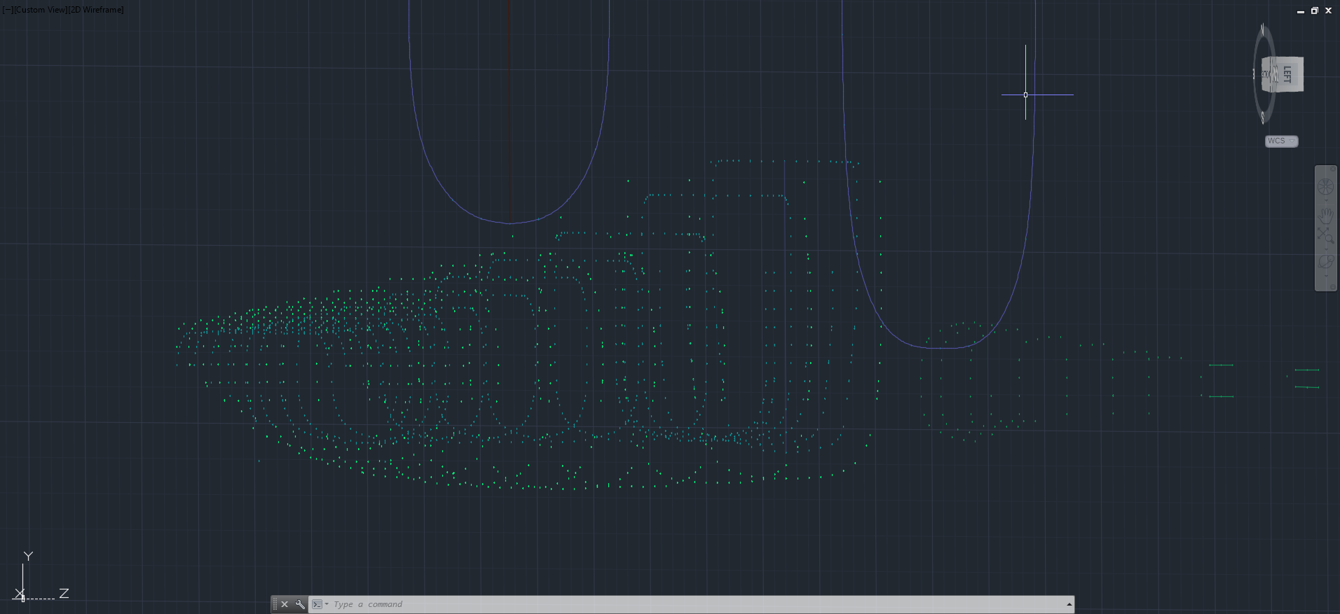
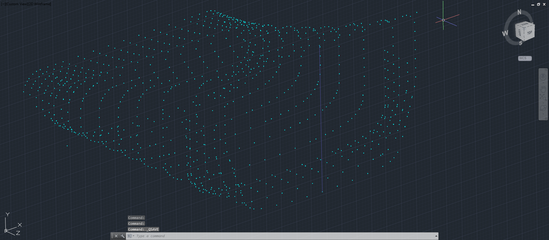
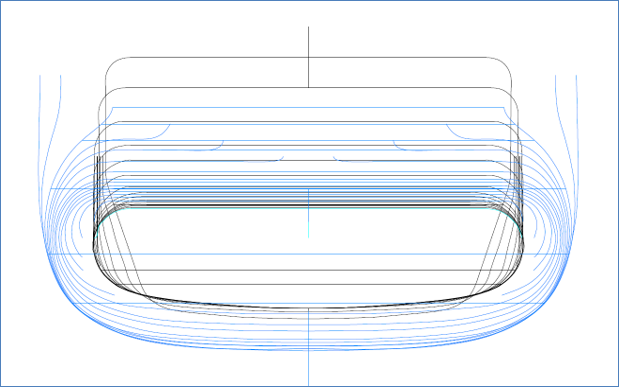
The first screenshot is all points combined with the local fuselage contours shown for reference; the second screenshot is the internal point cloud. All these points would then be contoured in Autocad to determine suspect locations and any orphaned points.

The external point cloud had 6 points prominently out of sync with everything else which turned out to be an error in the original data set. This is not uncommon and is usually quickly resolved.

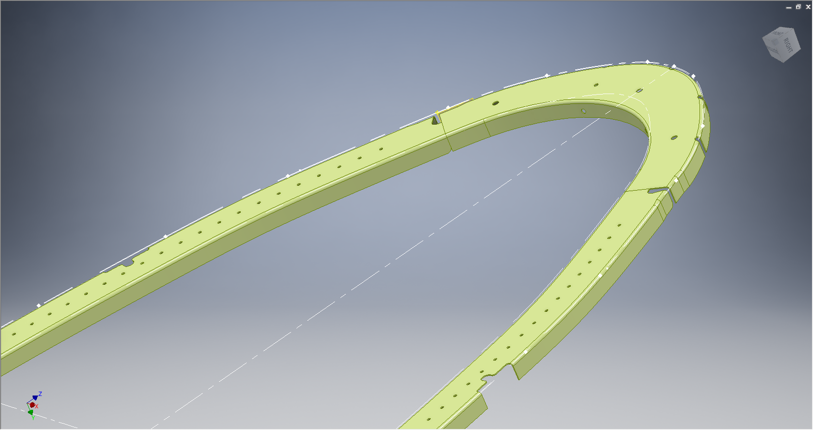
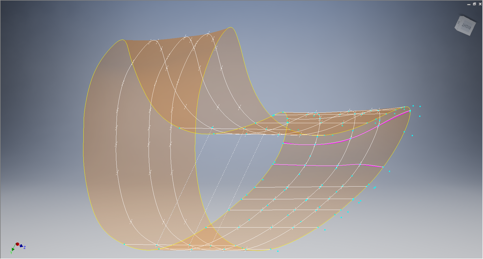
Once I have an initial dataset that satisfies these primary requirements I would then import this data into Inventor or Solidworks for evaluation as a surface in each case.

At this stage, I have spent about 3 days on the data preparation and would expect to spend at least a week to properly evaluate the surface definitions.

It can be very satisfying work when you see for the first time all these data points translated into something tangible as a 3D model depicting the end product first realized all those decades ago.

Update: Decided to pull out all the stops and complete the datasets and point clouds:       

North American P-51 Mustang: Fuselage

North American P-51 Mustang: Fuselage

The drawing archive I have contains quite a large selection of legible fuselage frame drawings which I am collating according to the Station reference on the fuselage. I have a spreadsheet that lists all the Mustang drawings including the original drawing number, the scan image number and location within the archive.

Each fuselage frame at each of the designated stations may comprise 3 or more elements, which unfortunately are scattered throughout the many rolls of scans thus requiring some exhaustive work with the spreadsheet data-sets to sort the numbers and folder locations in order to identify and collate the required frames for each assembly per aircraft type.

One such frame was at station 216 which I decided to model; partly due to the fact I was getting fed up looking at and sorting spreadsheet data.

2015-06-02_13-11-07 2015-06-02_00-03-52

There are several methods to modelling this and whilst I was subject to the vagaries and still limitations of the Inventor product (Solidworks has more options for working with splines) I developed a workflow that obviates some of these limitations and also how the end product is finished.

One way of doing this is to simply create a surface for the main plane and then project a flange line along the edge to create a”folded” surface and then apply thickness but this method gave some unusual iterations in the smoothness of the fillets at the end of the profile. I found that the best way is to create surfaces for all six faces; the splines inside and outside, the top and bottom planes and the ends, then sculpt to create a solid.

I would then go out about creating the notches and cutouts in the solid and then shell the solid to the required thickness. This works very well and ensures the integrity of the original spline ordinate lines (which would have to be split to do this any other way). This method also maintains better continuity of the end fillets and curvature (image 2).

The frame drawings reference the mold line ordinates, which I have for the P-51 B/C Mustang variants.The P-51D is similar with the exception of the ridgeback on the main rear fuselage that has been reduced above the +10″ W.L.

Techy stuff: I mentioned a limitation in the Inventor software which relates to creating a line perpendicular to a spline. In Solidworks you just sketch the line and constrain it perpendicular to the spline, but you cant just do it this way in Inventor (as far as I know). What I did was use sketch construction lines to define the point of intersection with the spline that I wanted the perpendicular line to start from. As I already had a surface projected from the mold frame spline (for above construction) all I had to do was create a new plane perpendicular to this surface at the selected point. It was then quite simple to create a further sketch to define the line I wanted perpendicular to the spline at the correct location.

North American P-51 Mustang: NAA Profiles

NAA P-51 B/C/D Mustang:

The majority of parts created for aircraft like the P-51 are derived from a library of standard section profiles, not unlike the steel and ship building industries. Fortunately for this project we have an extensive collection of these original NAA standard drawings, numbering 208 in total.

To facilitate the long term goal of recreating the P-51 part drawings as 3D models and associated 2D drawings I figured it may be prudent to first recreate the standard profiles as 2D CAD profiles for this purpose.

So far I have drawn the first 24 profiles exactly as shown on the original drawings but with dimensions in dual format inch & mm…many more to go!

NAA-1E1          NAA-1E1a

North American P-51 Mustang Project: Ordinates

NAA P-51 B/C/D Mustang

This is one of those projects that gets started and then for some reason gets put on the back-burner until now. One of the key reasons was due to the challenge of obtaining a good surface representation for the lower cowling for the P-51 B/C where I was having problems with the duct intake profile.

As usual I started with listing the ordinates in a spreadsheet and converting these to millimeters and extracting the X,Y.Z coordinates for further work in CAD.

I prefer to work in millimeters as I know that at so2015-05-30_19-31-32me stage the end profile may need micro adjustment which is so much easier to do using millimeter units.

This is a scrap view from the NAA drawing showing the ordinates table and the contours.

Thankfully for this part most of the ordinates were quite legible with only a few requiring interpolation; which would be done as a consequence of developing the data in CAD.

As it turns out there were a few orphaned ordinates that for some unknown reason did not align with the CAD developed surfaces; so these were simply ignored instead of trying to invent a purpose for them being there!

2015-05-30_20-39-59The drawing (right) shows the end result of transferring the spreadsheet data into a CAD product. This drawing is simply a record of the translation process and surmises the ordinates in relation to the Thrust line and Fuselage Reference line.

The main body of the cowling did not present any real problems but the intake duct portion did.

This area is less than 3 inches deep and is actually quite a complex surface; so any small deviation from exactness results in some crazy surface deformations. The original data tables are actually extremely good requiring only one small adjustment to get the result I was after…the trick was identifying which ordinates to use for the end profile and which ones we needed to check we have it done right.

After many (about a dozen) test developments of surface development and interrogation of the original data tables to ensure correct translations I eventually determined the correct ordinates and profiles to use to get this right.

2015-05-30_19-30-34

The resulting surface is based on the selected original ordinates with only one requiring micro adjust. In most cases the adjustment is simply an error in interpreting the sometimes indistinct values in the original data where a 6 could be an 8 or a 3 could be 5.

The 2 magenta coloured contours are generated profiles from a surface section cut overlayed on the ordinate controlled contours from the NAA tables which provides a check to ensure the surface conforms to the original design.

This surface will be converted to a T-Spline surface to facilitate final development.

It may be that this particular part does not warrant this level of exactness nor indeed the time expended in getting to this point. However it is a testament to the many fine designers of this era to be able to reproduce their work that was done to an extraordinary degree of accuracy.

Update Jan 2021: A comprehensive Ordinate/CAD package incorporating all known ordinate data points is now available for download. See this post for details.

FW 190 & Ta152: Ordinates

FW190 & Ta152H: Ordinate Study

1-Ta-152H-captured-FE112-Germany-1945-01

The FW190 & Ta152 was a very intensive project as I delved into the intricacies of the fuselage, wing and rudder ordinates for both aircraft; a study accumulating a mass of data.

In preparing the models I adopted a modular approach to the development breaking the assemblies down into manageable chunks of information that align with the Bremen construction assembly documents.

Every aspect of the available manufacturers data, specifications and third party resources have been very carefully scrutinized and incorporated into this build. Cross-referencing of even the smallest detail drawings can yield surprising, almost minuscule amounts of information, that can have an impact on the finished product.

Aviation Projects Drawing Comments  2015-05-31_21-46-45  2015-05-31_21-45-522015-05-31_21-45-27

It may seem inconceivable to attempt to build a model of this type down to an accuracy better than actual manufacturing tolerances. However; as I have probably mentioned before; working with SolidWorks or Inventor this level of accuracy is critical to a successful build.

These illustrations give you some idea of the progress I made with this study. Of course, the data sets for this aircraft are incomplete so a degree of interpolation based on the best available information was used where required.

Ta152 Ordinate Spreadsheet package for wings and fuselage available:

Ta-152 Wing Ordinates

Ta152H Wing Layout:

2019-02-09_13-55-38