New Project: Standard Part Libraries
Many moons ago I started a project to develop libraries of Aeronautical standard parts according to the various National and International standards pertinent to aircraft design and maintenance noted in this article.
https://hughtechnotes.wordpress.com/2015/07/26/naa-p-51d-mustang-standard-part-models-specs/
Using the original standards from the wartime era and the updated, often replacement standards, I figured it would be a good idea to develop this project further. I am aware that there are many different CAD systems so it would be folly to just develop this for just one product.


The above products are currently available in the Resources Tab of this blog and though included with the Mustang P-51 Ordinate/CAD dataset are standard for many aircraft of this era and accordingly are available separately. This existing collection is already very comprehensive with over 300 parts modelled and listed, though these are in line for an overhaul and update.
Moving forward with this project I will develop the configuration spreadsheets exactly as per the original specification tables set out plus any additional dimensional data that will be required for modelling. This will be accompanied by a DWG file as a template to use when developing your own equivalent of an iPart. Essentially putting together a dataset that anyone can use regardless of what CAD system they are using.
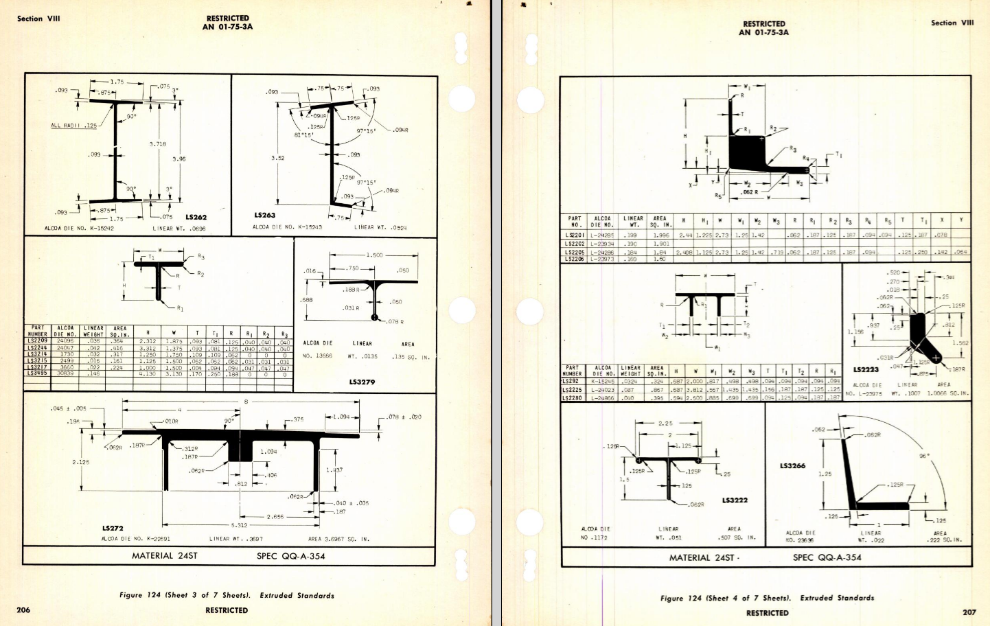
Additionally, standard metal work profiles will also be developed and produced in a similar manner.

There is a catch: This will take a while to do and probably won’t be ready until October. Typically the study will comprise a basic dimensioned drawing exactly as per the reference Standard with accompanying spreadsheets. There will be separate spreadsheets for each part number in a collective Standard, though there may be only one drawing. For example AN21 THRU AN37.
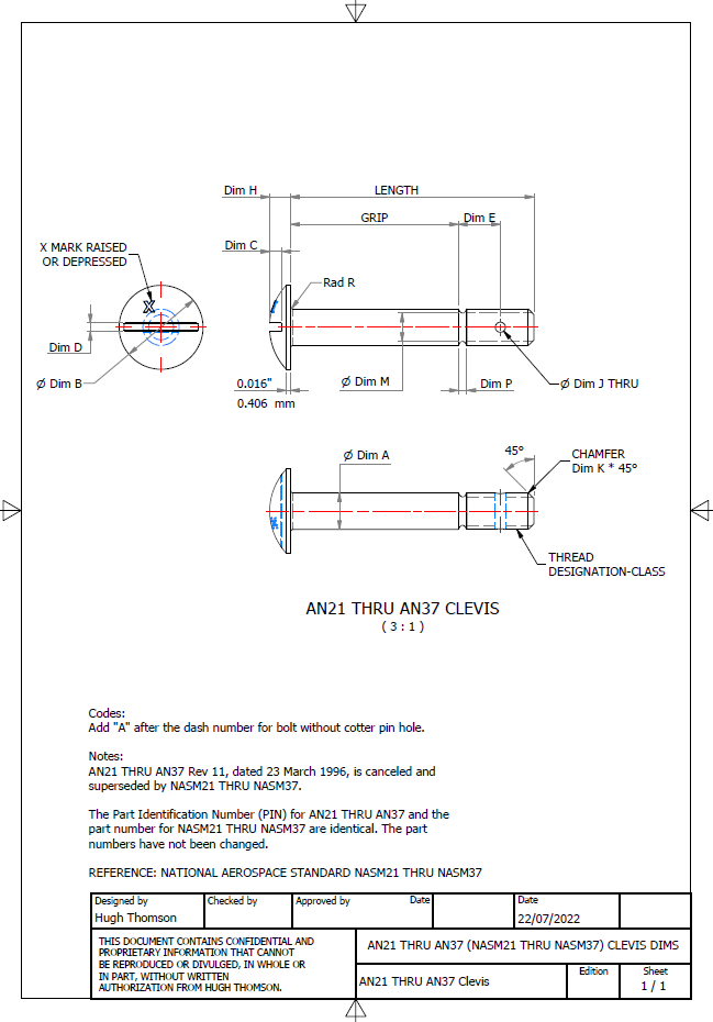

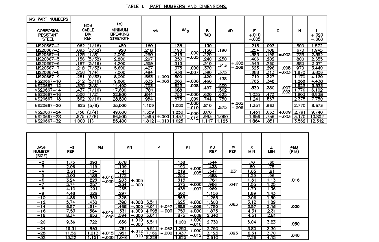
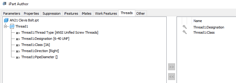
The way to use this dataset; regardless of the CAD system; is to first develop the part model naming the parameters as defined in the spec (you can use the DWG for your sketch template). In this example, the first 2 columns are generic to the specific CAD system with the first column being a unique value. From LENGTH to Dim P, in the table, these are the main geometry parameters. The Hole1 column has values “Suppress” or “Compute” which is an instruction to exclude or include the hole. The Thread parameters are defined as a Designation and Class which are standard integral parameters; those names may vary accordingly. Typically in Inventor, they can be found in the iParts Author as follows:
Once you have your Part modelled, open the iParts author and set up the first line of the table…you just need the first line at this stage Close the Author and open the table in Excel and copy the contents of the provided spreadsheet data tables above… ignore the header/titles. The iPart table will now be updated with all the above variations. It does not matter if your part template is Metric or Inches as the part dimensions are predefined as inches and will automatically recalculate depending on your template standards. You can of course already do this with the existing iParts but they are not inclusive of dimensioned drawings…so you have a bit more work to do referencing the actual standards for parameter names. That’s what this project work is designed to do…essentially finish with full documentation.


These spreadsheets and CAD profiles will enable anyone to very quickly develop a standard library in their own CAD system…an important resource and time-saving endeavour. I should note the actual AN and MS standards are available online for anyone that wants to access them. I have provided a link below to my previous article on this subject.
https://hughtechnotes.wordpress.com/2022/02/17/technote-manufacturers-standard-parts/
Update 27th July 2022:
Blimey, this is quite an awesome task…I envy those that build the standard libraries in the many CAD systems that contain thousands of parts…this will definitely take a long time.
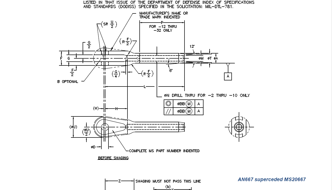
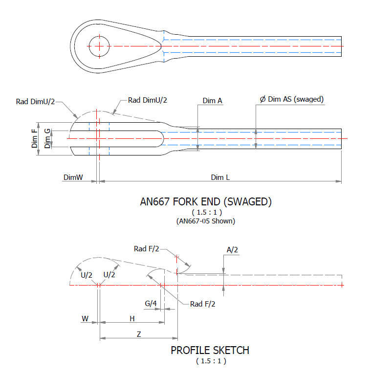
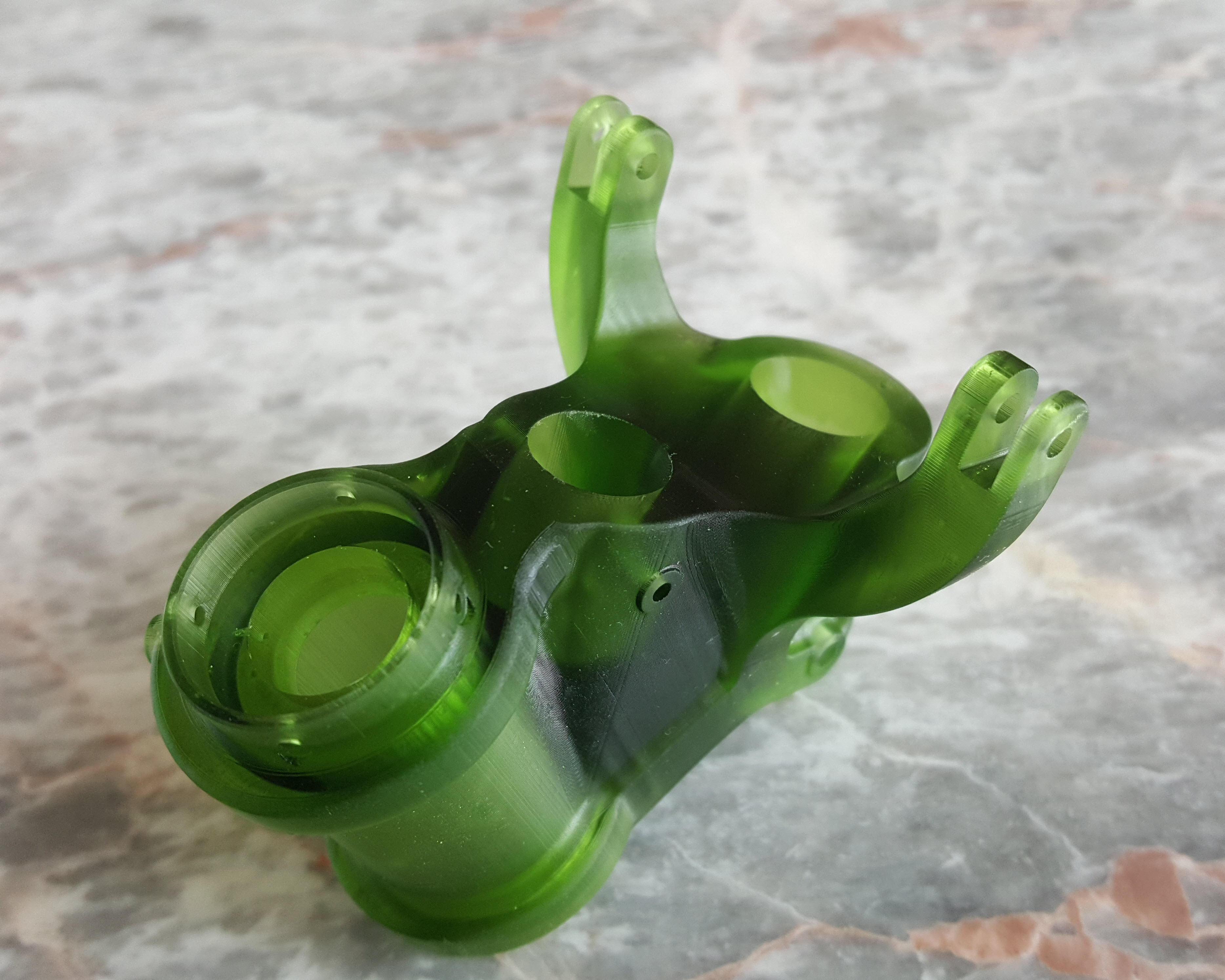
Many of the parts are relatively straightforward like Bolts, Castle Nuts, Clevis Pins etc that require nothing more than basic dimensioned drawings. Occasionally though many parts will require additional sketches to clarify the profiles, like this AN667 Terminal Fork End. Also in similar cases, the model will be dimensioned to As-Fitted/Swaged for use in assemblies. You can basically ignore the Scale as all the DWG versions of these drawings will be 1:1 according to the part number actually modelled.

This is a list of the Specifications I am currently working on. Many of these are updated versions of the existing standards available on the CAD Resources page. The updates include marginal improvements to the 3d models, additional data and verification of listed dimensions. The data sets also include dual part numbers where an item has been updated to a newer standard the new designation is noted alongside the old.
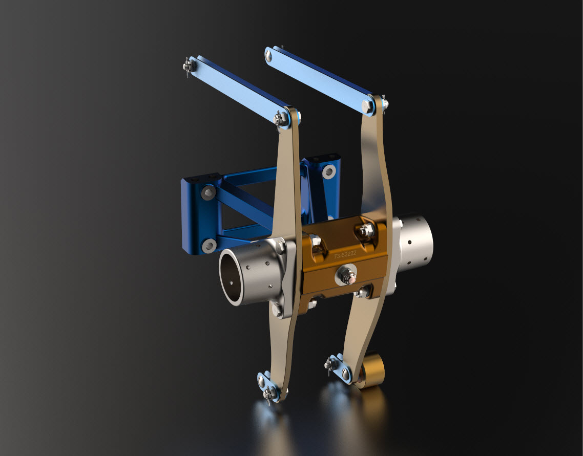
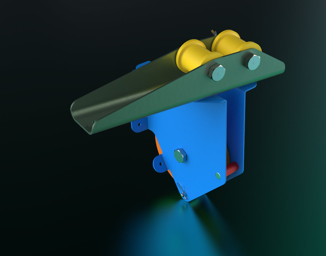
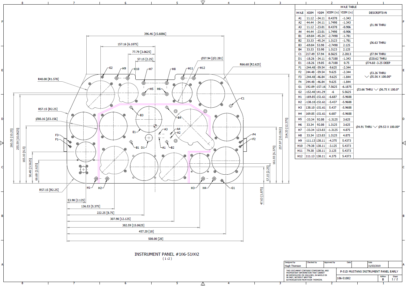
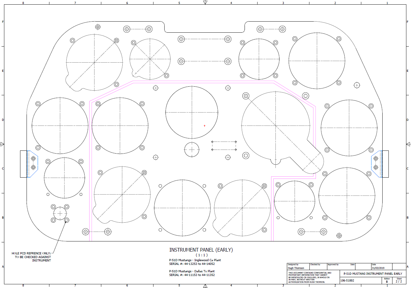
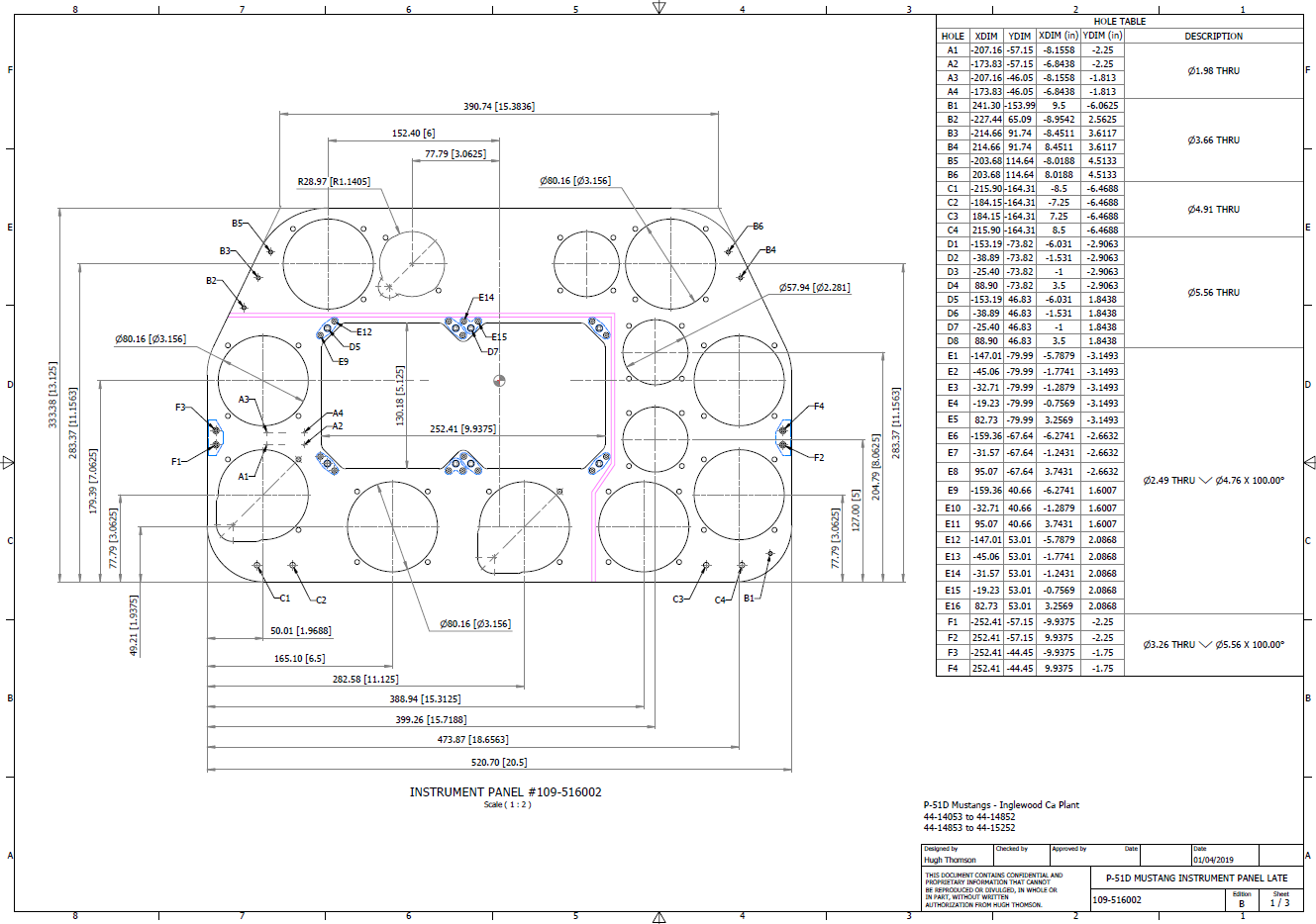
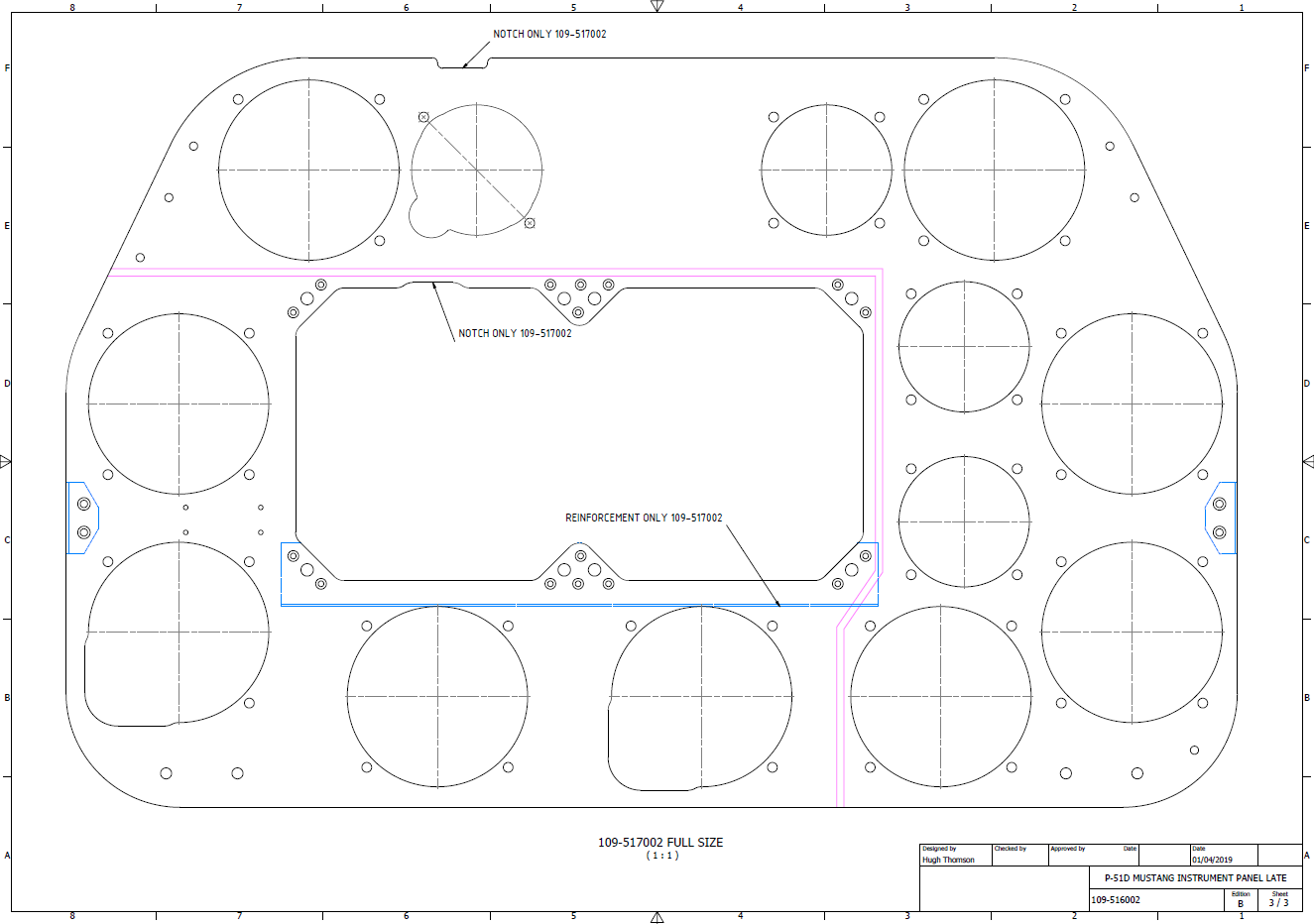
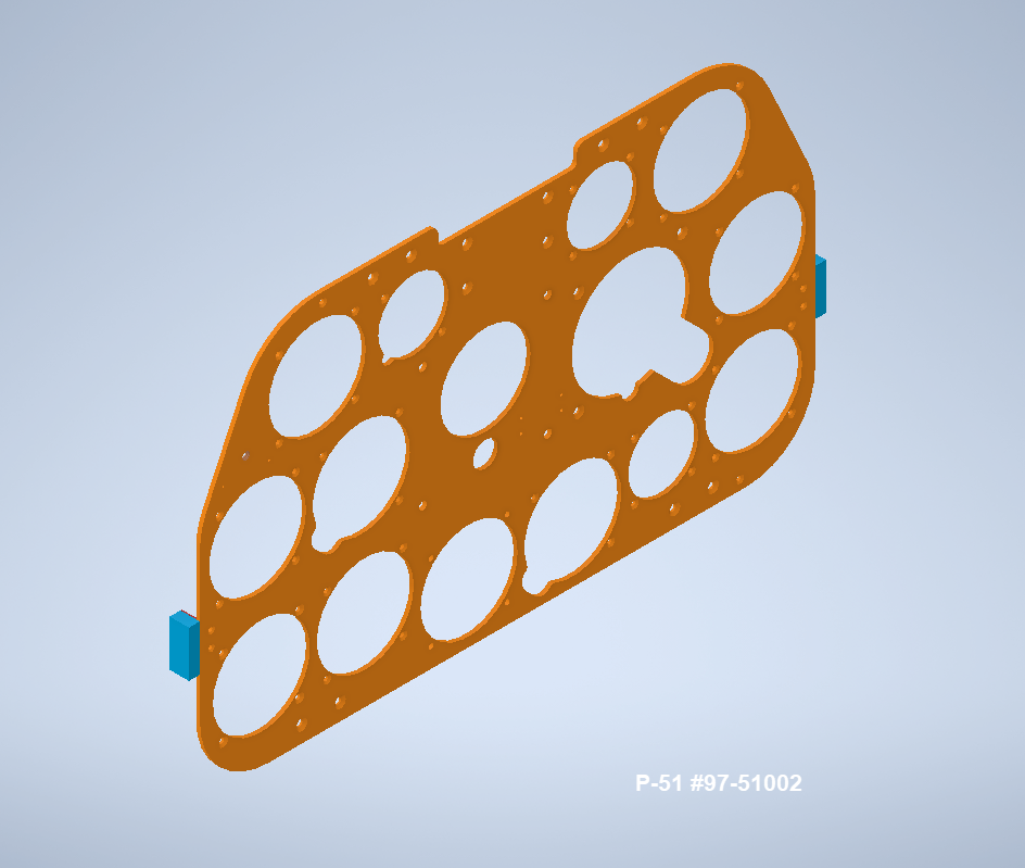
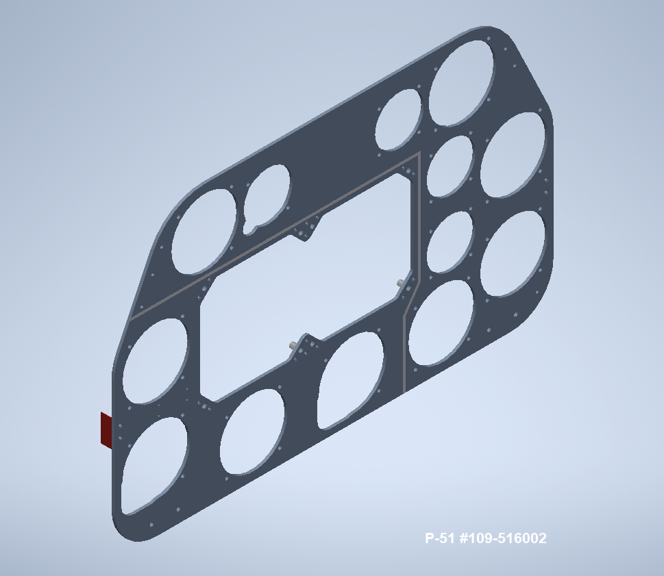
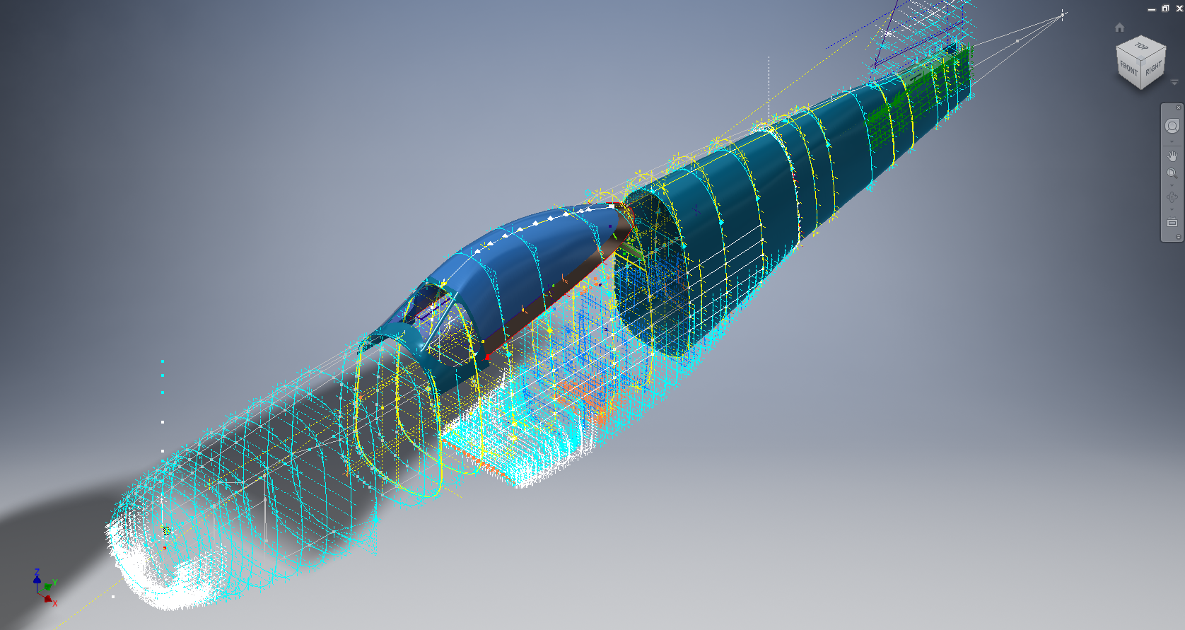
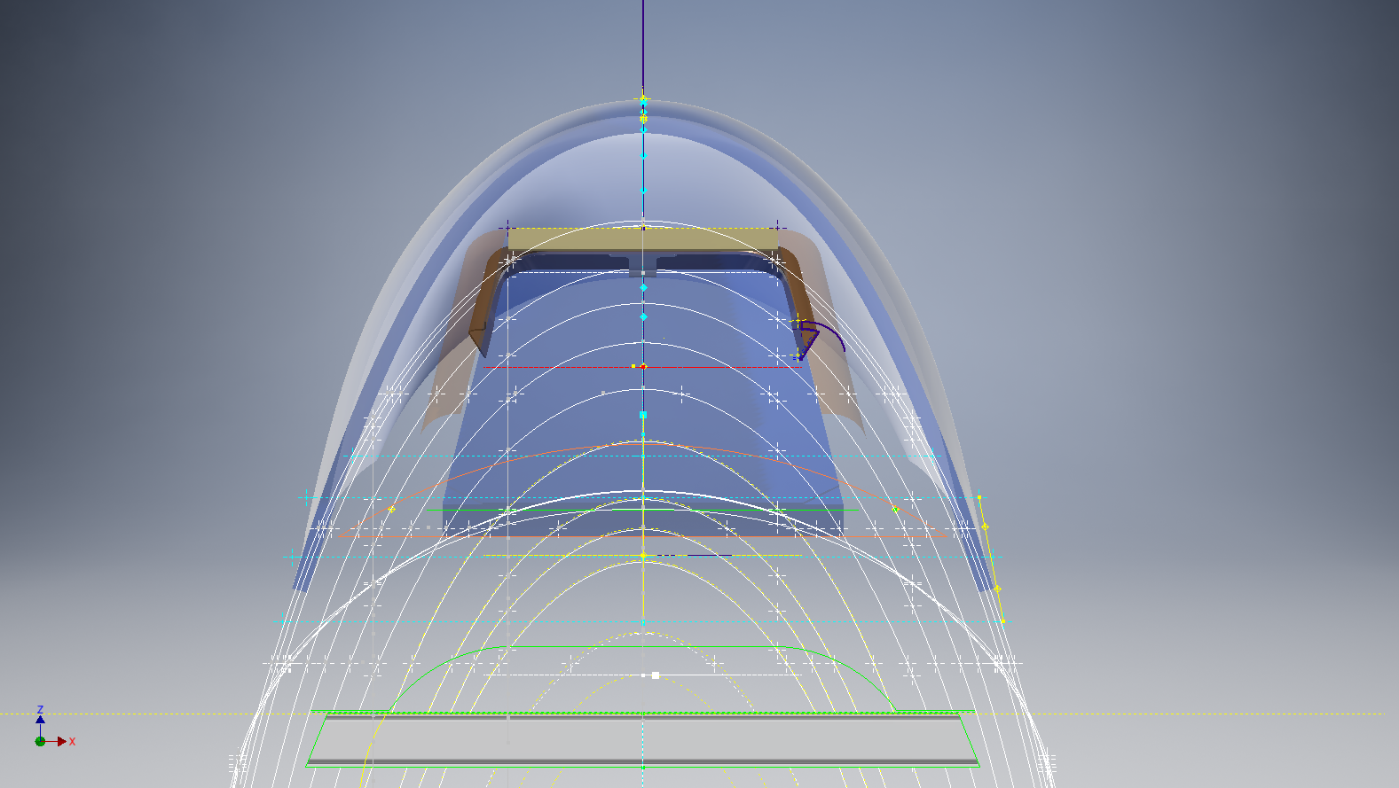
It is very important to get this stuff right, to ensure the part designations and representations are correctly defined in the assemblies. Have you ever tried to figure out assembly configurations from the NAA assembly drawings or picked your way through the Parts catalog just to identify a single connection for a clevis, nut and bolt, turnbuckle or whatever…it is time intensive. It was this desire to bring clarity to these assemblies that I created the P-51 Mustang cad models shown below, which incidentally was the catalyst that drove the development of these Part libraries.


Get in touch with any inquiries at the usual email. hughtechnotes@gmail.com


 The original formula for one of the constants “P” is given as shown (1). If we enter the formula as prescribed in a hand calculator it will evaluate correctly but will not work correctly in Excel in this format. So we need to tell Excel to essentially divide everything in the top line by everything in the bottom by adding parenthesis as shown (2).


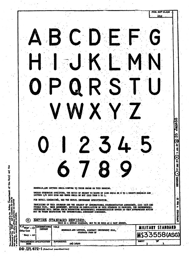 Using this font in CAD systems will result in problems with embossing or extruding.


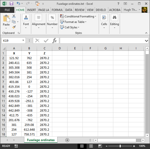
 For use in Cad systems like Autocad, it is recommended to collate these in a TXT file by simply copying and pasting.