Technote: P-38 Lightning Flap Guide Tracks:
The P-38 project is a study I have been working on for a while. In previous posts, I have covered the development of the Boom, Empennage, and Dive Flaps…even did a video on Youtube for the latter. Many of these studies are designed to research the operational characteristics of the component parts and this new study of the wing Flaps is no exception.
Essentially the flaps are split on either side of the Main Boom, with one being fitted at the Centre Section and the other at the main wing. These are activated by hydraulically controlled push and pull tubes with preformed carbon steel cables.

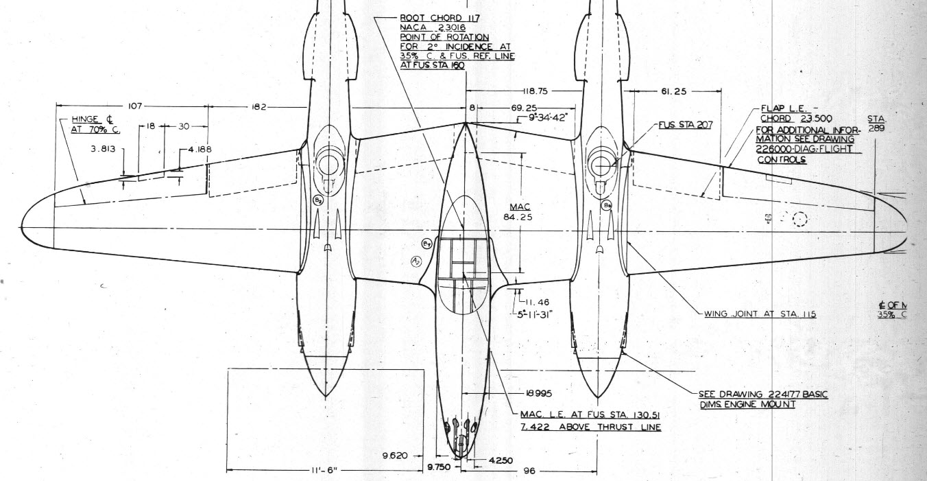
The extent of the operation of the flaps is controlled by guide tracks at each end, which incidentally is where this part of the project starts.
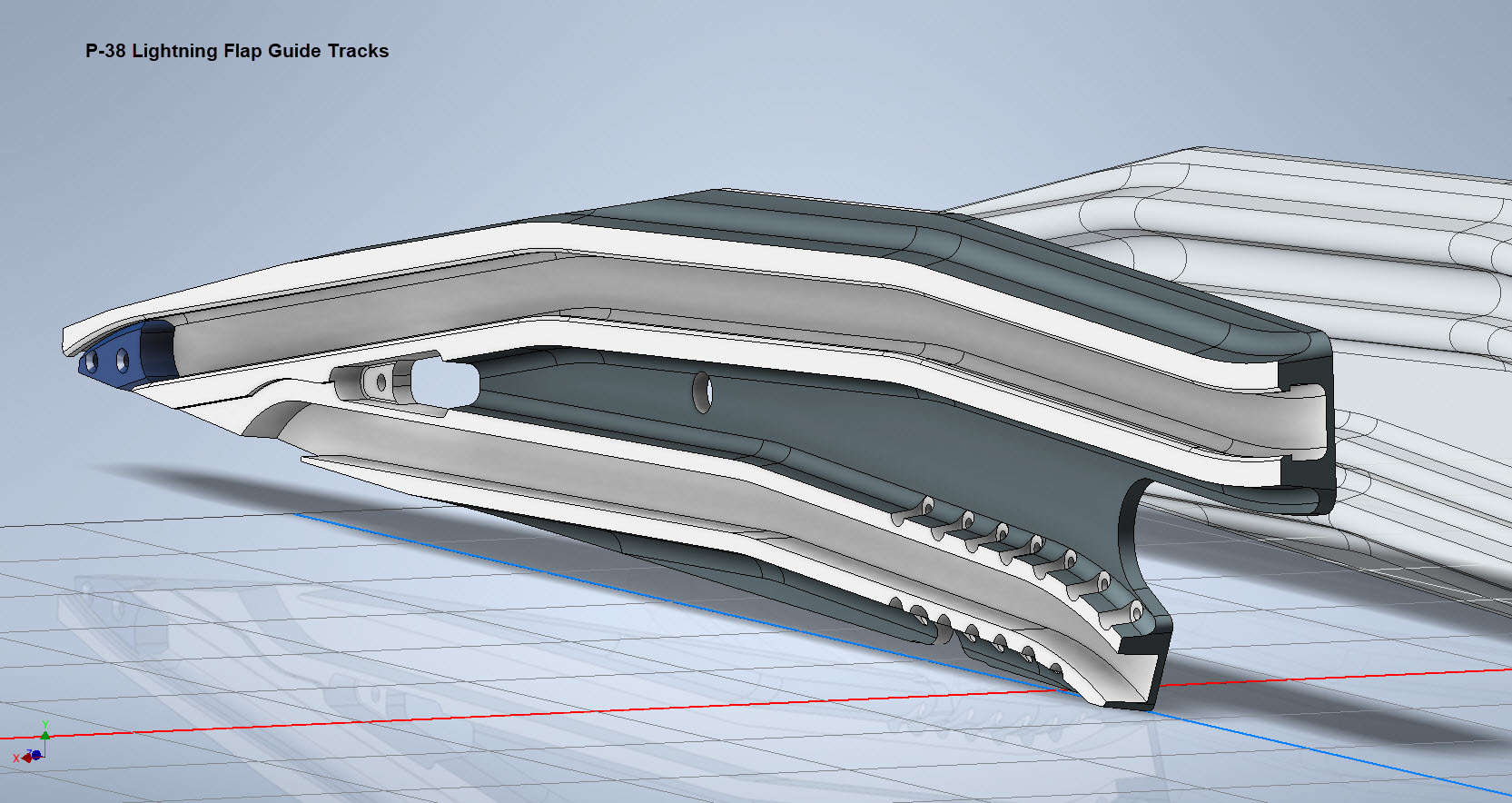
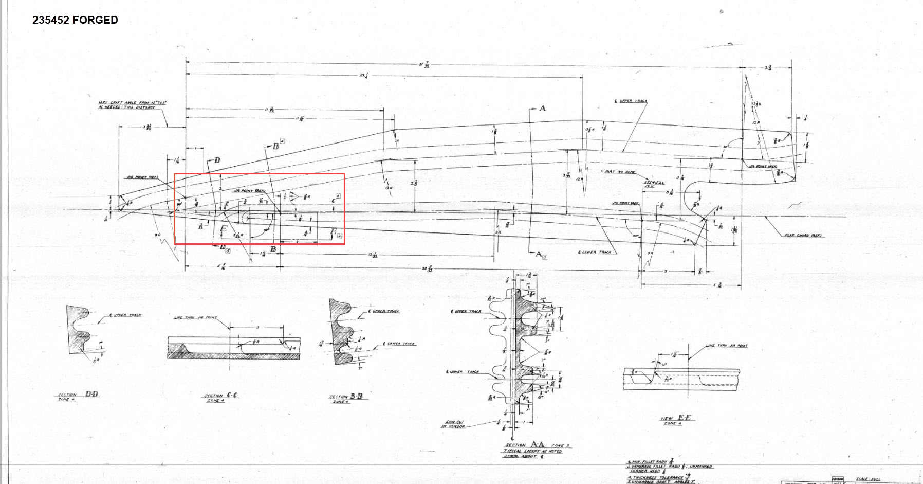
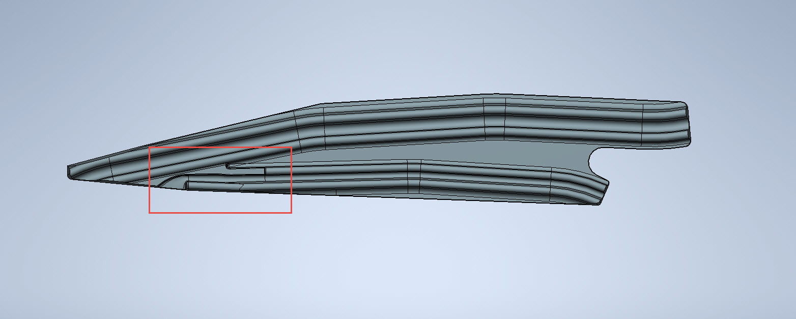
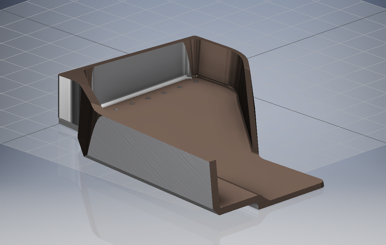
These guides are machined solid from forged Alumimiun blocks. In the image above the machined part is shown with the original forging in the background. It comprises 2 tracks with the upper track just over an inch wide and the lower track slightly smaller at 0.835″ wide. The blue part at the extreme end is a separate stop block.
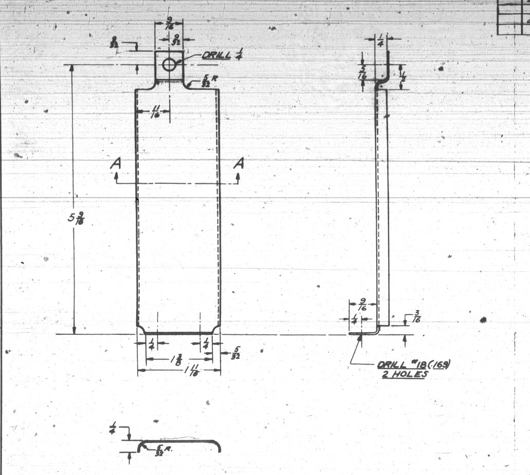
I am currently working through the variations of these tracks for each location and although some minor differences they are all based on one type of forging, part #235452.


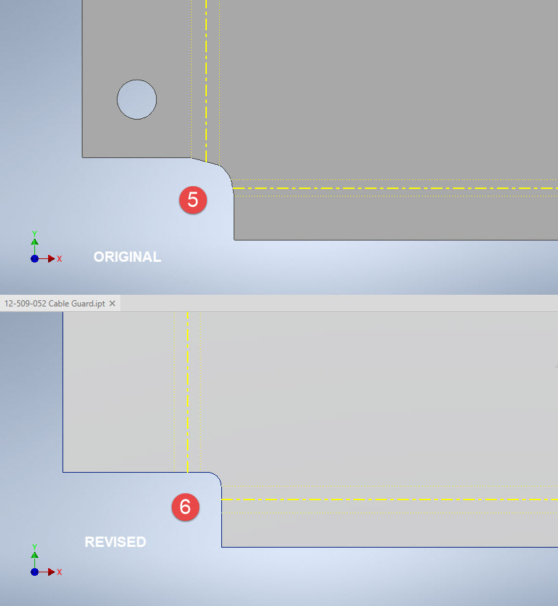
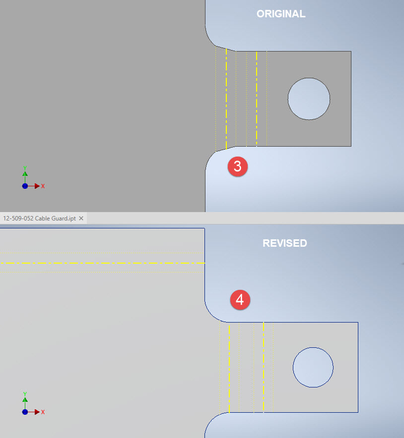
The forging drawing is not too clear about the definition of the track at the left-hand side which appears to drift slightly from the main track center. Understandably the lower part of the track walls deviate to align with the edge of the forging and therefore the main upper wall portion will adjust accordingly. I have improvised in developing this area and now that the project has further progressed there are a few minor changes I would make should this part ever be required for actual production. At this stage, my primary objective is the operational characteristics that are unaffected by this as the end product is the machined component that is derived from this forging.
Update: 26th March 2023:
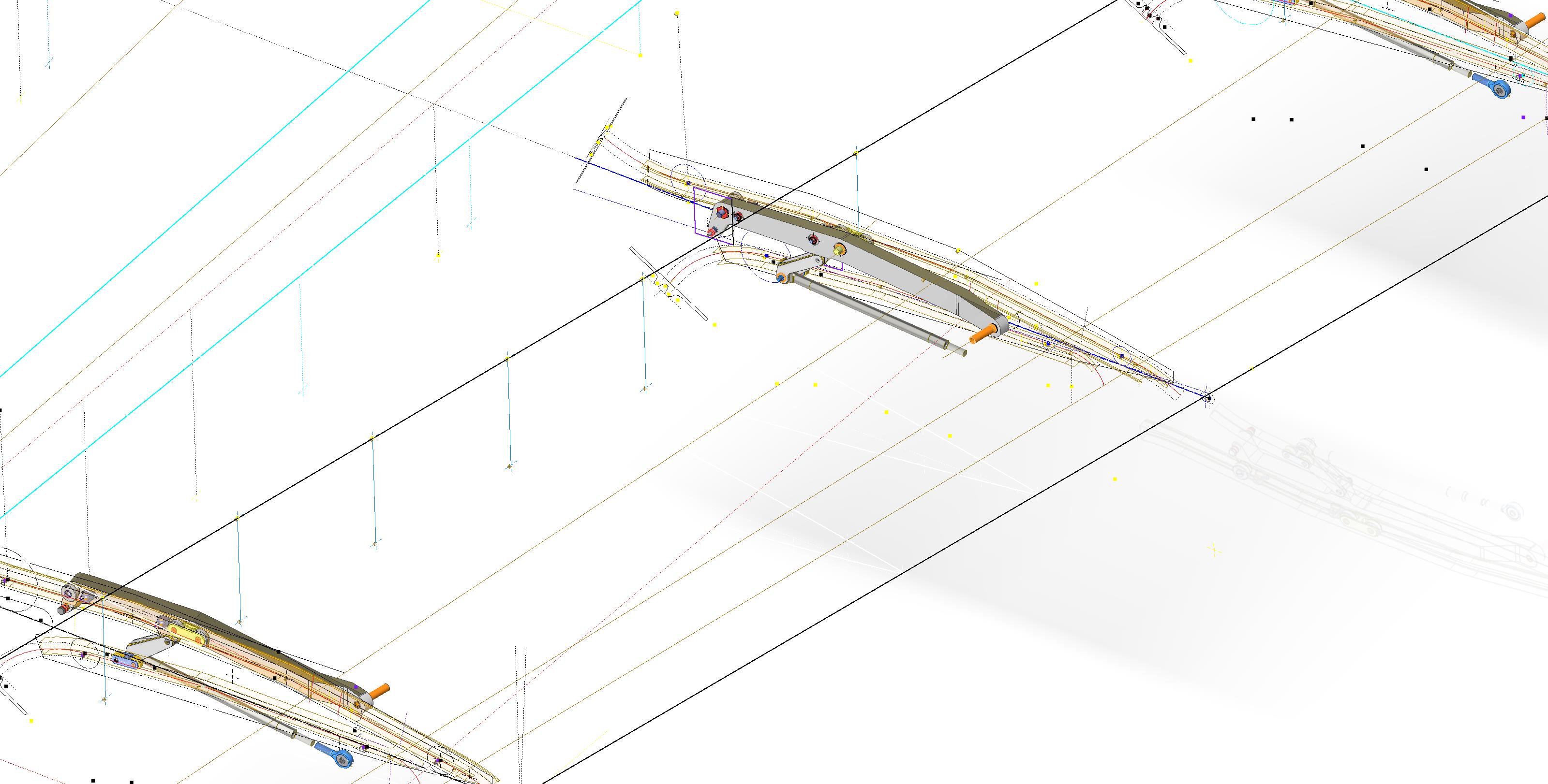
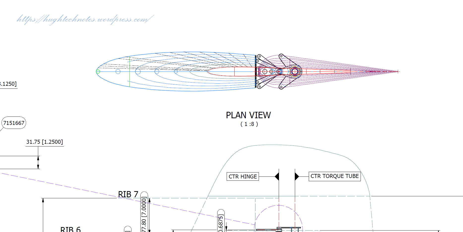
Making good progress on the Wing Flap mechanism with the Carriage Assembly now complete except for a few standard AN nuts and Washers. The Carriage Assembly also shows the track surfaces to demonstrate the correct relationships between the rollers and the track.


The second image above shows the adjustable roller at the front end of the carriage. This is achieved by the use of an eccentric bushing item #221832 which fits into the retaining locking ring item #221741 at increments of 30 degrees.
Update 30th March 2023:
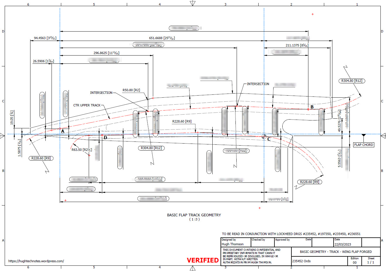
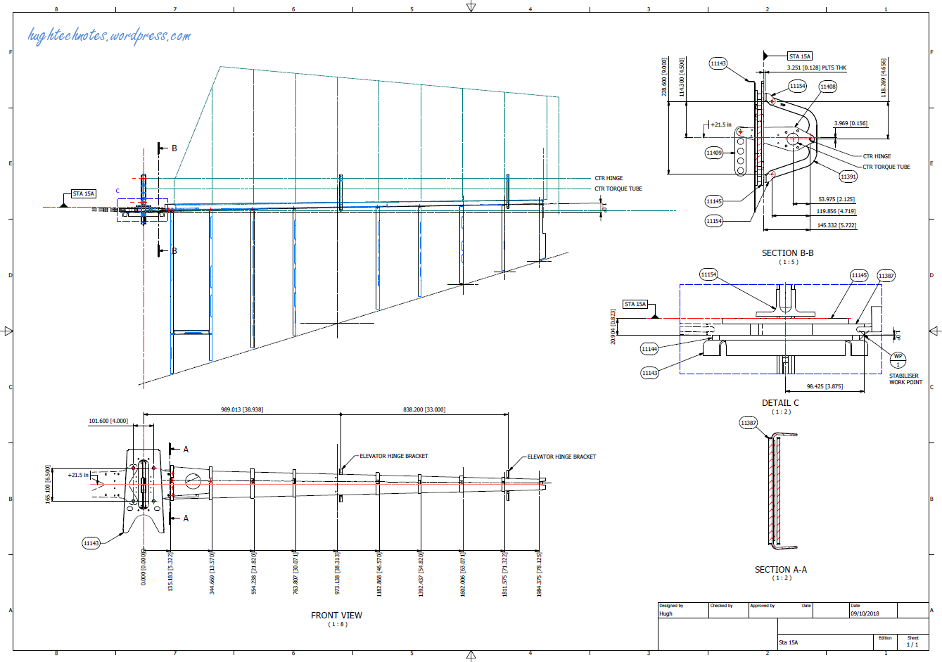
Have spent a considerable amount of time researching and resolving macro dimensional variation for the Flap Track guides. When I talk about macro I am looking at close to 1/128″ or 0.2mm…but it is essential to get this correct. The dimensions are blanked out for obvious reasons as this stuff takes a lot of time to research and develop.
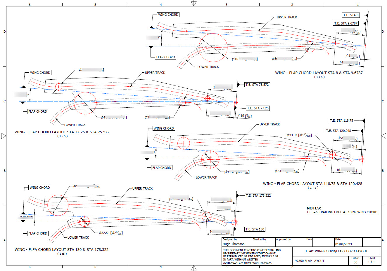
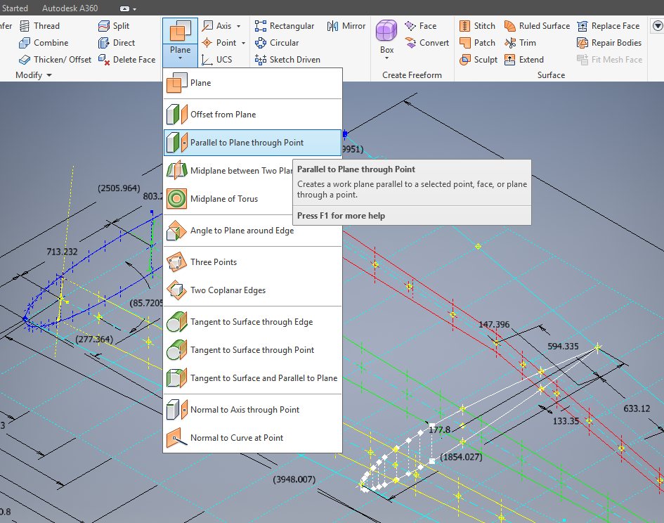
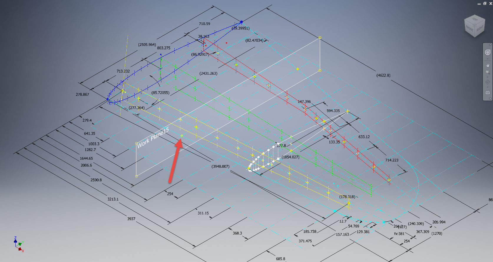
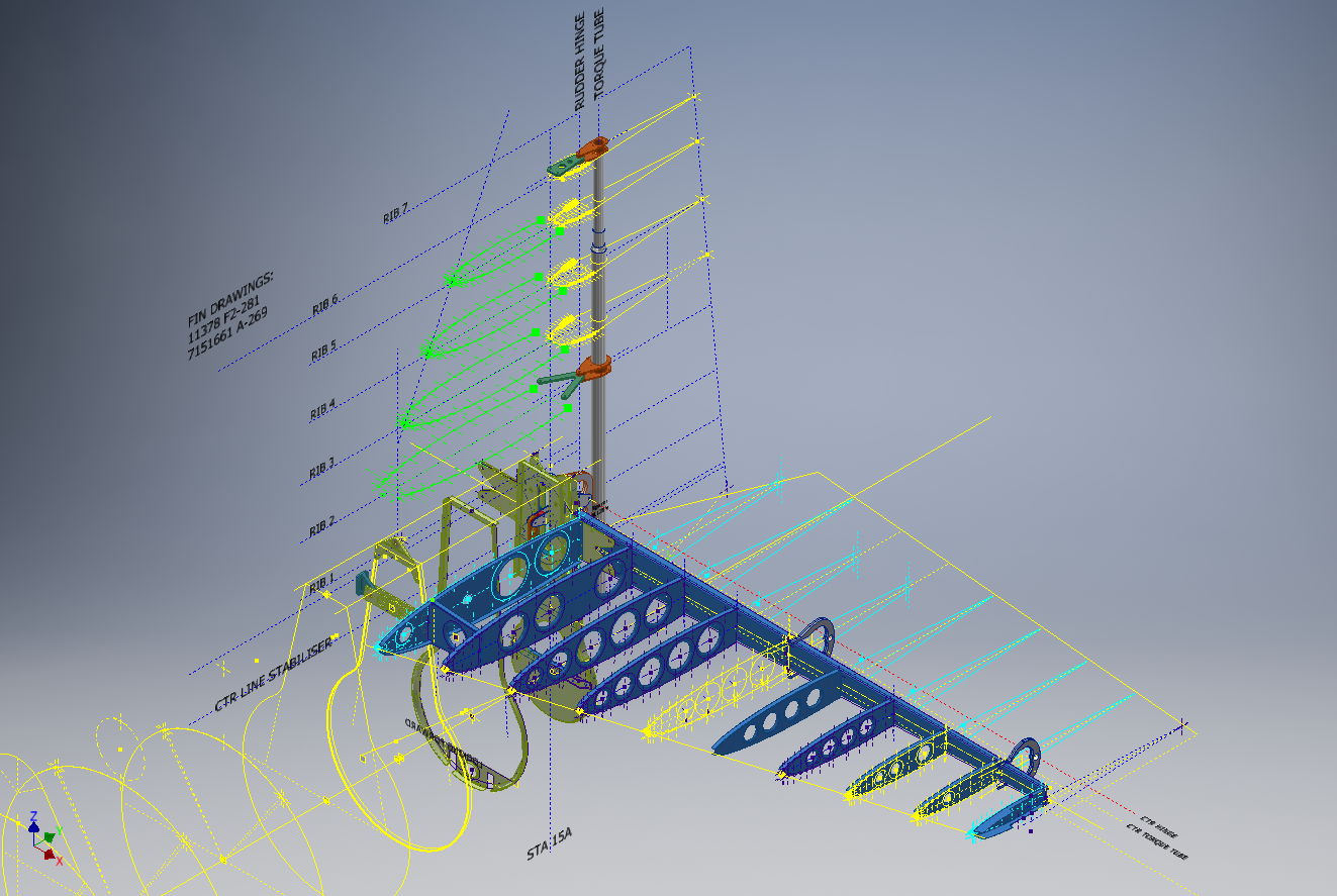
Finally located the Flap Track assemblies in their exact position on the wings. I will actually build the final assemblies as 2 separate items; one being the Inboard Flap and the other the Outboard Flap. For now, the initial plan was to get to a point where the tracks are accurately positioned and ready for the next phase which will be the Flaps themselves. The final stage will be a working simulation to determine operational parameters but we are a long way from that goal at this time.

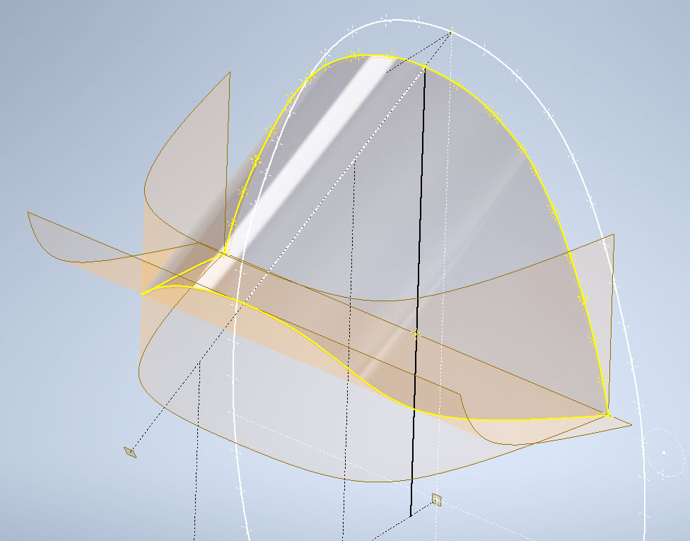
The tracks are currently shown in the assembly as surface models which keep it simple, however, when I get to the stage of finalizing the assemblies this will be fully modeled. This part of the project was surprisingly complex to achieve and every dimension has been cross-referenced and checked against known data…at one stage I had over 21 drawings one at the same time.
To help establish the starting point for the Flap Crriage I have an outline sketch of the key runner positions to which I later constrain the carriage parts in an assembly. It is actually quite a useful technique to use sketches to help establish relationships when building an assembly.


In summary, it is often beneficial to use surfaces in lieu of solid models for clarity when building these types of models as it is so much easier to see the key relationships between the main elements. Also using sketches to help align component parts in an assembly is a good work method and can also be used later when creating 2d drawings.
This more or less covers the basic setup for the Flap Tracks and carriages…the next article will focus on the Flaps and the eventual final wing Flap assembly.
.
.
.


 The technique I used is described in this video on


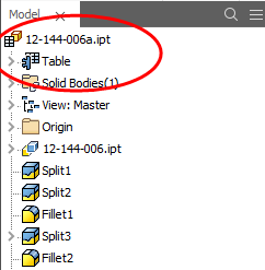 This creates a Table which appears in the model browser. It is usually a good idea to give parameters meaningful names as I have done here for the Length, Width and Height.