Restoration Project: Corsair F4U-1

Restoration Project: Corsair F4U-1

This is great news; a good friend of mine has just acquired the wreckage remains of a Corsair F4u-1.

IMAG1368

The long-term plan is to restore this Corsair to its original specification as a standing exhibit. It would be wonderful to restore to flying condition but the projected cost as it stands is quite overwhelming and to achieve flight status would probably double that.


IMG_4038.JPG

P1060200.JPG

We will be setting up a dedicated blog and website to record progress on this restoration. Part one of the project is to develop a master lines plan which will be used to design the jigs required to rebuild the fuselage and wings.

Any contributions to the project, regardless of how small will be greatly appreciated.

Grumman F6F Hellcat: Ordinates

Grumman F6F Hellcat: Ordinates

I am without access to a Cad system for a few weeks so I decided to spend time reviewing my archive collection. Whilst looking through the many aircraft in the archives I came across some interesting information for the Grumman F6F Hellcat.

F6F-3_Hellcat_11_of_VF-2_on_the_catapult_on_board_the_carrier_USS_Hornet_CV-12_May_6_1944

The archive consists of a substantial number of the Grumman drawings, varying in quality from very good to very poor, though I should clarify the latter relates to only a small number of drawings. This archive includes ordinate tables for the wings and fuselage so I figured it might be a worthwhile project to attempt to decipher and create a set of ordinate spreadsheets as I have done previously for the Mustang P-51.

Hellcat ordinates

Though I rather like this aircraft it was not a priority project on my to-do-list, but having spent today studying the Grumman drawings this could turn out to be a rather challenging project.

Fuselage Work in progress:

hellcat ords 2

Update:

hellcat prelim 2I have managed to obtain a trial copy of the Inventor LT so I can now move ahead with this project. This first interpretation of the fuselage profiles is actually not bad at all. A few macro adjustments will be required to get the profiles correct, mainly due to the quality of the archive where roughly 10% of the values are very difficult to read.

Each point represents the ordinate of the longitudinal stringers which I will profile to assess the alignment and curvature as an aid to finalizing the frame ordinates. Perfecting the frame ordinates can become quite tricky at this stage, requiring constant referencing of the original drawings including the frame structures themselves which often provide additional information that can assist with this process.

NAA P-51D: Master Lines Plan

NAA P-51D Mustang: Master Lines Plan

The P-51D project is progressing well with further developments on the fuselage frame profiles. I now have a comprehensive Master Lines Plan incorporating additional information obtained from mathematical analysis, drawings, reference documentation and geometric developments. I have updated and remodeled the underside Oil Cooler Air intakes, canopy, windshield, rear fuselage and fuselage tail-end. As part of the remodel the groups of ordinates for each frame for the Oil Radiator Duct, Coolant radiator Duct and Removable Scoop are now contained on their own respective work-planes. This will make it much easier to micro manage the final mold lines.

Fuselage Master Lines Plan (P-51D overlaid on P-51 B/C):

2017-07-01_14-32-09

Test Lofts and developments:

2017-07-01_14-30-24

Front Views (note the Canopy Profile update from the previous article):


A month ago I was not sure how much could be achieved given the limited amount of information at hand but with due diligence and detailed research, it is quite amazing what can be accomplished.

With this template, it is now technically possible to accurately develop a CAD model for the entire fuselage structure and mechanical components for the P-51D, which would be great; but I often wonder what the value of such an undertaking would achieve, other than being a darn interesting thing to do and a test of CAD modeling skills.

Having achieved this significant milestone the time is right to conclude the work on the Mustang P-51D and P-51 B/C projects. I may continue with the P-39 project but as always I am keen to explore the options for the more obscure extinct aircraft as described in Operation Ark.

2017-07-01_00-15-20

If you are planning on developing your own Master Lines plan a good place to start would be with the 1000’s of ordinates points cataloged and recorded on the spreadsheets here: Mustang P-51B/C Ordinates which also includes the wing ordinates for the P-51D and vertical stabilizer.

NAA P-51D Mustang: Using Ordinate Data

NAA P-51 Mustang: Using Ordinate Data Spreadsheets

A question arose during a telecon today about using the Ordinate Spreadsheets for Cad and Modelling.

2018-11-30_08-40-04

Typically for the fuselage and cowlings, the spreadsheets are set out as above. The top section replicates the layout of the original manufacturer’s drawings specifically to allow traceability for verification purposes. The section below, bordered in blue is the concatenated values from the top table in a format such that the values represent the actual X,Y,Z coordinates for each point.

2017-05-23_21-47-42For use in Cad systems like Autocad, it is recommended to collate these in a TXT file by simply copying and pasting.

Once collated open Autocad, select the Multiple Point feature and cut and paste the entire contents of the TXT file onto the command line which in turn will import the values as points.

For other CAD systems like Inventor the preferred format is an excel spreadsheet with 3 column headers X, Y and Z.

All we have to do is to open this same TXT file from Excel as a comma delimited file, check the options presented in the opening dialogue to ensure correct formatting and save the file as an XLS. Remember to label the first row as X,Y and Z.

2017-05-23_22-06-55

When you start a sketch in Inventor there is a feature on the toolbar to import Excel data. When you import the data there are a few self-explanatory options.

2017-05-23_22-12-58

There are of course many ways of doing this and it will vary according to what CAD system you use. Importing all X, Y, Z points in a 3D sketch, for example, will align the ordinates with the current UCS, which in some cases may not be desirable. The Z value is the Frame or Station location relative to the aircraft datum, which essentially translates to being the work plane location. The X, Y values are typically the sketch coordinates normal to the work plane.

If you are working on a 2d sketch and importing the set of points as X, Y, Z values; Inventor will only import the respective X,Y values and ignore the Z value, in fact, it will notify you that it is doing this.

Update: July 2018

The ordinate spreadsheets now have an additional page that compiles the ordinates for each frame with the X,Y,Z components listed separately. This makes it easier to manage the ordinates depending on what CAD system you are importing to.

2018-07-31_23-24-09

If you require any further information then please drop me a line.

Mustang P-51 B/C Ordinates

Mustang P-51 B/C and P-51 D Ordinates:

P-51BC Layout

I have had a number of requests for the ordinate spreadsheets I developed for the Mustang P-51 B/C and D fuselage, cowl, cooler and air intakes, so I have decided to make them available to all; which could save you considerable time and effort.

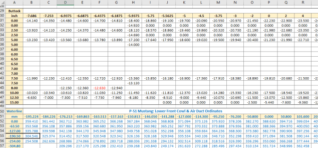
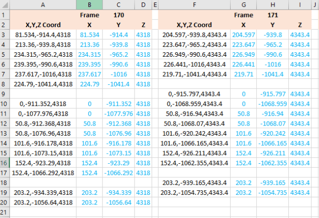
The ordinates are listed on 10 separate Excel workbooks with 18 spreadsheets for all known ordinates from manufacturers data. The ordinate listings are in both mm and inches with the X,Y,Z coordinates extrapolated from this data-set for ease of transferring to a suitable CAD system. The total points listed are literally thousands.

P-51 D Layout102-00005: Fuselage (BC main)
102-00006: Fuselage (forward to cowl)
102-00007: Removable Scoop (fuselage, Int and Ext)
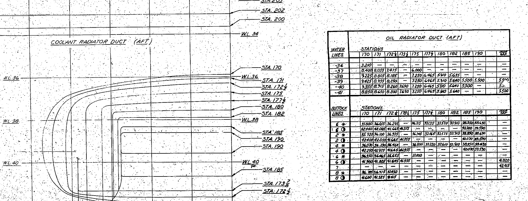
102-00008: Coolant Radiator Duct (Aft Section)
102-00008: Coolant Radiator Duct (Fwd Section)
102-00008: Oil Radiator Duct (Aft)
102-00009: Carb Air Scoop (Cowl)
106-00006: Wing (P-51D)
73-00006: Wing (P-51BC)
 
+ Autocad DWG Fuselage Frame & Wing Profiles P-51 B/C and P-51D (ref only)
NAA Master Dimensions Report (wings, fuselage, landing gear).
Include scans of original source documents for reference.
 
The spreadsheets are not locked or protected so you can manipulate the core data to suit your own applications.
The P-51D fuselage profiles are reference only due to being mathematically generated based on original NAA methods and thus are not verified.

This represents a huge number of hours worked, meticulously listing each ordinate individually and then creating cad drawings to check the ordinates and derive the ordinates that are unclear on the manufacturers’ drawings.

2016-06-04_23-33-26

The ordinates for the P-51D wings comprises 2 sheets; the first listing the tabulated data as per the original manufacturer drawing and the second extrapolated to compile the X,Y,Z coordinates for input into CAD.

P-51D WING ORDINATE

P-51 Wing Profiles

Update 20 Aug 2019:

The spreadsheets now include the OLEO undercarriage and general tidy up of datasheets for consistency. Now probably the most comprehensive and complete dimensional study of the P-51 B/C and D. 2018-09-20_22-45-40

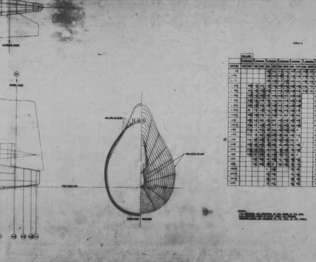
Horizontal Stabiliser and Fillet Ordinates layout:

Mustang P-51 BC

Sample data for P–51B/C and P-51D;

For further details see this more descriptive post or send me an email to HughTechnotes@gmail.com 
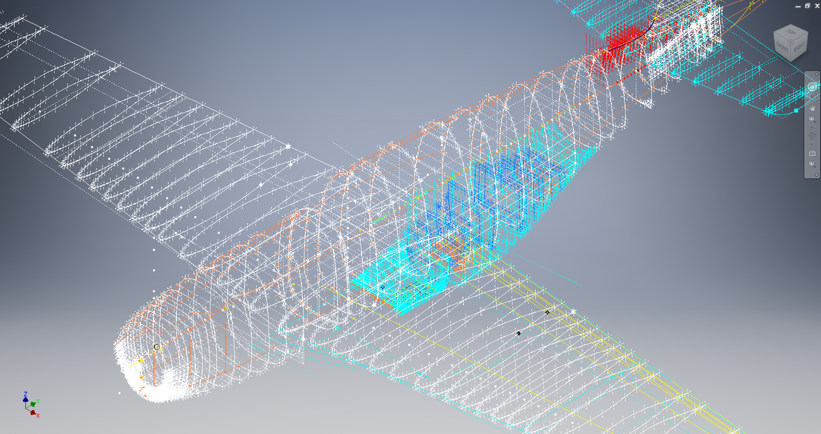
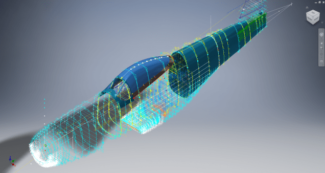
2D Draughting to 3D Models

2D Draughting to 3D Conversion

2d to 3d
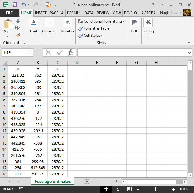
Technical drawings, detailing the specifics of your design can be critical for the communication both internally and externally. We can transform your 2D CAD or fully dimensioned legacy paper drawings to 3D Models using our experienced engineers to ensure drawings are 100% accurate and adhere to the most relevant standards and protocols.

3D Cad models will be fully inclusive of manufacturing tolerances as specified. New 2D drawings will be derived from the 3D model, dimensioned and denoted as original.

Attributes and BIM IFC data can be incorporated according to your engineering and company standards for Structural, Mechanical, Building Services and Equipment projects.

We normally use the Autodesk Inventor but are equally capable with all the Autocad based products from which we can provide native format model files or various other formats to suit your requirements, including DWG, IFC, STEP and STL.

We can provide CAD modelling services for your restoration project, adhering to all appropriate standards and design specifications.exit

Topology optimization and additive manufacturing

Topology optimization and additive manufacturing

This is probably a slight divergence from the main subject of Historical Aviation though it does align well with the underlying research philosophy relating to the how and the why of how the aircraft designs develop from concept to manufacture.

Engineers have always strived to maximize efficiency with materials, reduce weight and improve manufacturing…the shape and form being integral to that same desire.

Thus today we have many tools at our disposal that have evolved to interrogate and simulate our designs before they become a real world object. In recent years Topology Optimization, an industry term that Wikipedia defines as “A mathematical approach that optimizes material layout within a given design space,” could be a critical motivator to create industrial designs more efficiently with less material…an ideal environment for the aircraft designer.

In my day job as an engineer I am always looking for new tools to help me make my designs better and more efficient. In my studies of historical aircraft designs I attempt to get into the designers mind and understand the motivations and inspiration for the aircraft designs.

So I am naturally curious about the many influences that impact the design process and the tools available to do that job.

This is a link to a youtube presentation on Topology Optimization..just because it is; for me personally; an incredibly interesting technology…enjoy!

Solidthinking Inspire; Topology Optimization

2015-08-17_22-23-48