P-38 Lightning: Looking for Mold Line Drawings!

P-38 Lightning: Looking for Mold Line Drawings!

I am looking for 6 Mold Line drawings for the P-38 Lightning. These drawings are the Cowl Mold Lines for the engine encasement.

Lockheed drawing numbers: 195072, 195081, 232543, 232544, 232545, 232764.

I can obtain a small number of key dimensions from the panel drawings which will not be enough to achieve an accurate full profile. I do hope someone has a copy.

I have tried all the usual sources for this information without success.

I can’t offer you much for the drawings but I am willing to share the comprehensive ordinate study and cad material when this project is complete.

Further Request: Photos of Wing Tip Required:

The wingtip trailing edge has a tab extension as a consequence of the connection of the top and lower panels. I am curious as to how this extension integrates at the extreme tip of the wing. If anyone has any close-up photos for the wing tip I sure would appreciate a copy.

Let me know if you can help. Email hughtechnotes@gmail.com

Update: 21st May 2022:

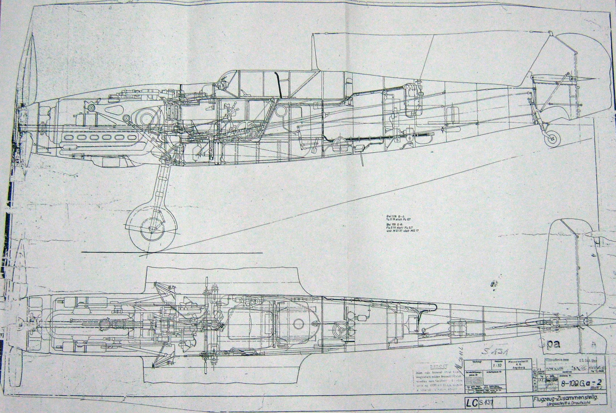
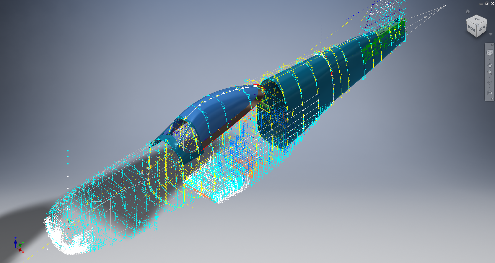
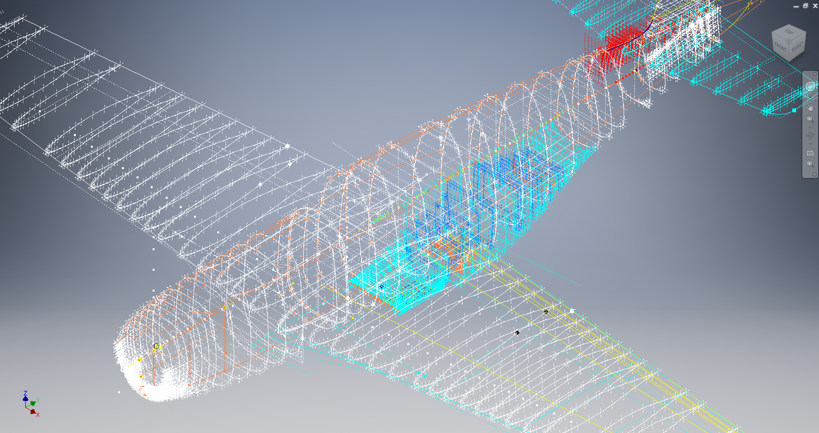
I have not had much luck with sourcing the above material. The Mold drawings would certainly have been enormously helpful in determining an accurate ordinate model. There is a Plan B, though it is going to be a fairly intensive search for every morsel of information that can be gleaned from the individual part drawings, manuals and reports that collectively will give me enough to achieve an accurate definition of the FWD Boom and Engine cowl surfaces.

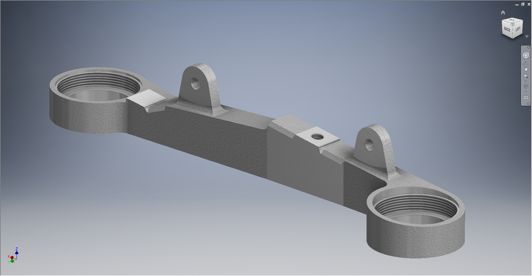
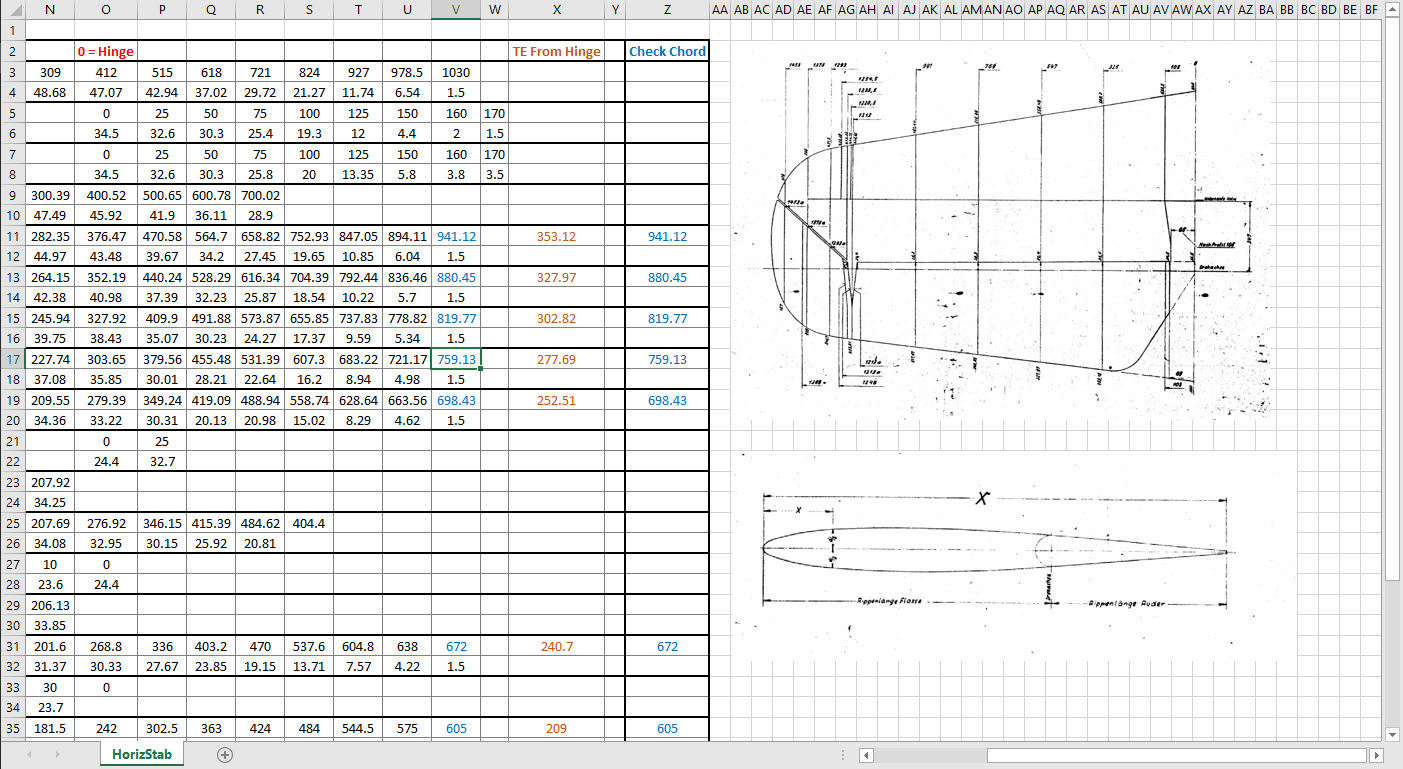
An example would be the Scoop web plate profiles shown above to achieve some surface definition in those areas. I am currently working on the Landing Gear doors which will help define the lower surfaces. This is a lot of work which unfortunately means this will not be ready until much later in the year. I don’t do guesswork, if the ordinate point does not exist it is not on the model.

If anyone has any information that can assist me with these ordinate points, please, please do get in touch.

Technote: Manufacturers Standard Parts

Technote: Manufacturers Standard Parts:

Every aircraft manufacturer has libraries of standard parts in addition to the MIL specs that are used for their various aircraft designs. These vary considerably covering a wide number of standard parts like bolts, nuts, washers, hinges, screws, grommets, extrusions etc, etc.

When I was working on the P-51 Mustang Tailwheel mechanism I was forever jumping back and forth looking for the various standard parts which was a nightmare due to the large number of files in the archive. This was further complicated as the file names were the scan numbers and not the drawing names. So I figured it was time to get this stuff organised.

I have worked through the archives for the Grumman F4F Wildcat and F6F Hellcat and extracted the Standard Part drawings and renamed them with the correct drawing designations. I have also done a similar exercise for the NAA P-51 Mustang.

The actual drawing filenames have been adjusted slightly to make sorting easier (by group) and make the names more legible. Where for example we have 1E48; this is denoted as 1E-48…the 1E is the alpha-numeric group designation with the numerical sequence suffix. This just makes it easier to read when you have hundreds of files in the same folder.

The excel spreadsheet is a register with the different manufacturers’ part drawings listed on separate sheets in one workbook. This is tabbed along the bottom of the spreadsheet. It is envisaged that each set of drawings as listed will include a download link to an online resource to access the files. This download link for the collection of standard part drawings is located on the top right of the spreadsheets.

The NAA Part Drawings also include the previous specification identifier as some of the earlier blueprints still refer to this number.

This is an evolving project and will be continually updated as more information becomes available with the inclusion of other manufacturers data. Currently, over 400 part drawings are registered. For further information please drop me a line at hughtechnotes@gmail.com.

Update: This file Revision A containing the Standard Part drawing links for Grumman and NAA is now available for download here. https://drive.google.com/drive/folders/1KQbn8FNCwKO8xODLlPB3jTAExa3qygZJ?usp=sharing

Footnote: If you are looking for MilSpecs; as discussed in a previous post; then check out these resources:

https://quicksearch.dla.mil/qsSearch.aspx

http://everyspec.com/MS-Specs/MS2/MS21000-MS21999/

Messerschmitt: Bf109 Ordinates

Messerschmitt: Bf109 Ordinates:

I recently received an inquiry from a museum regarding ordinate datasets for the Bf109. As I previously mentioned in this earlier post the archive I have has a lot of data that was done by others…so I figured it was quite comprehensively covered.

Anyway, I decided to have a closer look and see what was actually documented and how well it aligned with known data. It turns out to be a bit of a muddle. Although the data is quite well presented I have uncovered a number of inconsistencies and anomalies which I will need to resolve.

8-109.000 G-2 Flugzeug Zuss 2

What I thought would be a quick response to an inquiry has initiated a much more intensive study which admittedly I had not planned for. I will go back to basics with this one, using the existing data as a reference and develop a new set of ordinate data for the Bf109 similar to how I approached the Mustang P-51 project.

I have already started with the Horizontal Stabiliser and part of the way through the Vertical. The tables will essentially be a reconstruction from the Messerschmitt drawings and then compiled to develop the X, Y, Z ordinates for transfer to CAD.

bf109


NAA P-51D: Master Lines Plan

NAA P-51D Mustang: Master Lines Plan

The P-51D project is progressing well with further developments on the fuselage frame profiles. I now have a comprehensive Master Lines Plan incorporating additional information obtained from mathematical analysis, drawings, reference documentation and geometric developments. I have updated and remodeled the underside Oil Cooler Air intakes, canopy, windshield, rear fuselage and fuselage tail-end. As part of the remodel the groups of ordinates for each frame for the Oil Radiator Duct, Coolant radiator Duct and Removable Scoop are now contained on their own respective work-planes. This will make it much easier to micro manage the final mold lines.

Fuselage Master Lines Plan (P-51D overlaid on P-51 B/C):

2017-07-01_14-32-09

Test Lofts and developments:

2017-07-01_14-30-24

Front Views (note the Canopy Profile update from the previous article):


A month ago I was not sure how much could be achieved given the limited amount of information at hand but with due diligence and detailed research, it is quite amazing what can be accomplished.

With this template, it is now technically possible to accurately develop a CAD model for the entire fuselage structure and mechanical components for the P-51D, which would be great; but I often wonder what the value of such an undertaking would achieve, other than being a darn interesting thing to do and a test of CAD modeling skills.

Having achieved this significant milestone the time is right to conclude the work on the Mustang P-51D and P-51 B/C projects. I may continue with the P-39 project but as always I am keen to explore the options for the more obscure extinct aircraft as described in Operation Ark.

2017-07-01_00-15-20

If you are planning on developing your own Master Lines plan a good place to start would be with the 1000’s of ordinates points cataloged and recorded on the spreadsheets here: Mustang P-51B/C Ordinates which also includes the wing ordinates for the P-51D and vertical stabilizer.

Mustang P-51 B/C Ordinates

Mustang P-51 B/C and P-51 D Ordinates:

P-51BC Layout

I have had a number of requests for the ordinate spreadsheets I developed for the Mustang P-51 B/C and D fuselage, cowl, cooler and air intakes, so I have decided to make them available to all; which could save you considerable time and effort.

The ordinates are listed on 10 separate Excel workbooks with 18 spreadsheets for all known ordinates from manufacturers data. The ordinate listings are in both mm and inches with the X,Y,Z coordinates extrapolated from this data-set for ease of transferring to a suitable CAD system. The total points listed are literally thousands.

P-51 D Layout
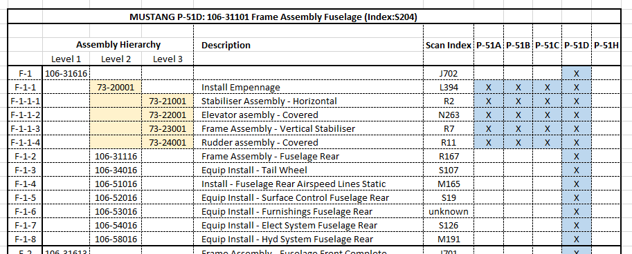
102-00005: Fuselage (BC main)
102-00006: Fuselage (forward to cowl)
102-00007: Removable Scoop (fuselage, Int and Ext)
102-00008: Coolant Radiator Duct (Aft Section)
102-00008: Coolant Radiator Duct (Fwd Section)
102-00008: Oil Radiator Duct (Aft)
102-00009: Carb Air Scoop (Cowl)
106-00006: Wing (P-51D)
73-00006: Wing (P-51BC)
 
+ Autocad DWG Fuselage Frame & Wing Profiles P-51 B/C and P-51D (ref only)
NAA Master Dimensions Report (wings, fuselage, landing gear).
Include scans of original source documents for reference.
 
The spreadsheets are not locked or protected so you can manipulate the core data to suit your own applications.
The P-51D fuselage profiles are reference only due to being mathematically generated based on original NAA methods and thus are not verified.

This represents a huge number of hours worked, meticulously listing each ordinate individually and then creating cad drawings to check the ordinates and derive the ordinates that are unclear on the manufacturers’ drawings.

2016-06-04_23-33-26

The ordinates for the P-51D wings comprises 2 sheets; the first listing the tabulated data as per the original manufacturer drawing and the second extrapolated to compile the X,Y,Z coordinates for input into CAD.

P-51D WING ORDINATE

P-51 Wing Profiles

Update 20 Aug 2019:

The spreadsheets now include the OLEO undercarriage and general tidy up of datasheets for consistency. Now probably the most comprehensive and complete dimensional study of the P-51 B/C and D. 2018-09-20_22-45-40

Horizontal Stabiliser and Fillet Ordinates layout:

Mustang P-51 BC

Sample data for P–51B/C and P-51D;

For further details see this more descriptive post or send me an email to HughTechnotes@gmail.com 

2D Draughting to 3D Models

2D Draughting to 3D Conversion

2d to 3dTechnical drawings, detailing the specifics of your design can be critical for the communication both internally and externally. We can transform your 2D CAD or fully dimensioned legacy paper drawings to 3D Models using our experienced engineers to ensure drawings are 100% accurate and adhere to the most relevant standards and protocols.

3D Cad models will be fully inclusive of manufacturing tolerances as specified. New 2D drawings will be derived from the 3D model, dimensioned and denoted as original.

Attributes and BIM IFC data can be incorporated according to your engineering and company standards for Structural, Mechanical, Building Services and Equipment projects.

We normally use the Autodesk Inventor but are equally capable with all the Autocad based products from which we can provide native format model files or various other formats to suit your requirements, including DWG, IFC, STEP and STL.

We can provide CAD modelling services for your restoration project, adhering to all appropriate standards and design specifications.exit

The Journey

The Journey:

This blog has been about the journey cataloging my passion for historical aviation design and construction. Its about the geometry; the ordinates and plans, about the designs and construction; from wood and canvass to full metal and alloy and the inspirations for the designs. The sheet metal work, the manufacturing, the mechanics, materials, electrics and hydraulics.

Its been an interesting time studying the different aircraft construction techniques and design methods. The different approaches to how different designers organise and develop the designs on the drawing board, sometimes accumulating 100o’s of drawings for a single aircraft…an admin challenge that even today would be quite daunting.

Not all my work has been published here, only a few examples that I think may be of particular interest. The evolution of the FW-190 to Ta-152, the various marks of the Spitfire, the early design characteristics for the Tiger Moth, the Mustang P-51 conic research and mathematical analysis culminating in a broad spectrum of research material that lays the foundation for the next chapter in my work.

I have learned a lot from this work which has been both challenging and frustrating. Its tested the limitations of my knowledge and the CAD systems we have come to rely on so much in our designs today.

Not many of the archive drawings sets I have are representative of a complete aircraft, often missing key information or simply illegible; though the latter sometimes can be overcome by studying other aspects of the design. I am often asked if I would consider creating an entire aircraft design in CAD that could actually be manufactured and whilst the answer is of course yes I would be reluctant to spend the considerable time required for any aircraft for which we have many flying examples.

Having said that Operation Ark was setup to undertake such a task for an extinct or rare aircraft depending on availability of sufficient design data. This work is still in progress and will take a while to resource, evaluate and fund such a project.

In the interim I have received a new set of archive material for an aircraft that was used extensively by Russia on the Eastern front which will be featured here in a few months time.

For now there wont be many updates but please do drop me a line as its always good to hear from the many readers of this blog about their own experiences in the exciting world of historical aviation.

Update: Mustang P-51 Project & Operation Ark

Update: Mustang P-51 Project & Operation Ark

The Mustang P-51 project is on hold whilst we review the CAD systems we will use for Operation Ark. To date we have utilized both the Autodesk Inventor & the Dassault Solidworks for our projects and research. We have another contender for the project which is Solidedge, until recently this was not a viable option but the latest version ST8 exhibits many of the features we would need.

Operation Ark will be a long term project requiring many man hours of work to research and build literally thousands of models, so it makes no sense to have different CAD products for this project. There is also a cost consideration as the project will rely entirely on goodwill and donations to support our efforts and assist with  CAD software.

Collaboration technologies and access to rendering farms for final processing of the CAD data are also key considerations. We have received offers of support from a few fellow enthusiasts to help with the Cad model developments and rendering; the latter being from Bilby…thank you very much for your support. Some comments from fellow enthusiasts:

From Alan “I love your Operation Ark initiative, and would be more than willing to play a role in any capacity.”

From John; “ARK is an extremely important project and I congratulate you on your vision.”

From Beaufort: “…I am really impressed with what you do and I can see that massive amount of time that you put into it. I also love the design specifics of these aircraft…”

Operation Ark Project Status:

Lockheed_Vega_5

This project is attracting a lot of attention, with many positive responses as noted including suggestions of alternative aircraft for consideration. One of which is the Lockheed Vega , which is a unique aircraft and was; in many respects; ahead of its time.

This is actually a good example for Operation Ark as the only remaining examples are located in the USA with only one flight worthy example, though further research would suggest that number could well be 2. The location alone excludes a large number of enthusiasts from actually ever seeing one either as a static exhibit or in flight!

That is part of what Operation Ark is about, removing geographic constraints and bringing access to everyone; the complete aircraft with everything modeled right down to the nuts and bolts. An exact replica in 3D that can be interrogated online as assembled or as individual components. We are also contemplating extending this to include additive or 3d printing technologies to build a half size replica, making the parts available to interested parties.

WEB11667-2010pBut this is only one of the aircraft being considered and whilst a likely candidate for selection; specifically as we have access to the manufactures drawings; our preference would be for one that does not exist or has only 1 example in existence like the Ta152.

The project though is entirely dependent on the availability of the original manufacturers drawings and specifications, which is our current priority!

Even when we do have access to materials they first have to be evaluated, which incurs a cost for scanning of microfilm archives and then reviewed for completeness. This process is rather costly but ensures that we don’t commit to a particular aircraft that we can only partially build. Usually where we have incomplete datasets we will endeavor to source the missing data elsewhere before we actually exclude the aircraft from selection.

All the research and work published here to date has been done voluntarily in the hope that it will help other enthusiasts.

NAA P-51B/C/D Mustang: Radiator Coolant Mount

NAA P-51B/C/D Mustang: Radiator Coolant Mount

I discussed in my last post the development of a comprehensive drawing register for the P-51 and my rather ambitious intent to derive the list of parts associated with each sub assembly and main assemblies.

This could indeed be quite a task as for example on the P-51C alone we have 348 assemblies listed, some are sub assemblies and some are top level assemblies. The challenge is organizing the drawing parts list according to their assembly and retain the order of links on my filing system as per the main document register.

2015-06-15_18-18-30The NAA Numerical part lists (AN01-60JE-4 Section 2) give us some idea of how this data can be collated but the chart lists the top level assemblies and does not follow the hierarchy to the individual part. The individual parts though are listed in subsequent chapters of the parts list.

The part files themselves also contain information to assist with establishing the hierarchy of assembly; similar to the following for the Radiator Coolant Mount.

2015-06-15_01-15-12    2015-06-15_00-46-18

As you can see from the scans this part drawing typically lists the associated next level assembly, quantity and the aircraft variants to which they belong.

2015-06-15_01-19-41This image on the left is the next level assembly (sub assembly) which shows the inclusion of fittings and bushings and again lists another next level assembly.

Typically this is how the hierarchy works and its great that we can track the target assembly from the individual part drawings.

2015-06-15_00-56-52This is the top level assembly as noted in the above drawing. Our Coolant Radiator Mounts are highlighted in red.

In this example we don’t have all the drawings for the parts listed and though it would seem unlikely to be able to build this assembly with incomplete information it may be possible to interpolate sufficient data from what we know to develop the parts that are not available.

This is typical of these types of projects as the majority of scan drawing sets are incomplete and many parts can only be developed from physical examples or interpolated where we have the requisite data from other sources.

This approach is similar to how I plan to tackle this document register in identifying the links between the part files and the assemblies. We have the NAA register; which is a great starting point; and the part and assembly files themselves. There may be instances where the information from the drawings or the NAA register is unclear, in which case I would refer to other drawings in the series that may reference this information in the notes or comments.

2015-06-15_23-39-34At this stage I have transposed the NAA register assembly chart (noted above) into a spreadsheet format so that I can add additional key information.

The image shown here is a partial screenshot of how the fuselage data has been organised, showing the hierarchy level of the main assemblies according to their respective position in the NAA chart.

The first column is a reference number I use for hierarchical lists of this nature. There is still a lot of work to be done to collate the parts associated with these assemblies; hopefully most of which I will be able to transpose from the NAA scanned register.

In the interim I shall continue to develop some of these part drawings into accurate 3d cad models.

2015-06-15_00-48-28