Technote: Learning Resource for 3D CAD!
Today I had an interesting conversation with a University lecturer on utilising historical blueprints as a resource for learning 3D CAD. I have been involved in similar discussions in the past and I do think they are an ideal source for those that are beginning this journey. I once helped a college to develop a curriculum for their students learning CAD on the principle that they would be more engaged in the learning process if they were developing a real-world object that they could actually relate to.


It does make a lot of sense and I would encourage new users to seriously consider the many benefits of using blueprint resources for learning. A typical aircraft design covers complex mechanical items, hydraulics, electrical, sheet metal, moulds, integration with external resources such as Excel spreadsheets as well as familiarising the end-user with tolerance application. Never mind the added benefit of how to prepare quality, fully dimensioned 2D drawings. All disciplines in one package!
I work with a lot of different CAD systems, not just Inventor, though the main reason for using Inventor is because it is accessible as a trial product more so than many others and that this industry is not one normally associated with Inventor…so it is a nice challenge. Occasionally, particularly with other CAD systems, I tend to evaluate them using the blueprints as source material to cover the many aspects of their functionality.
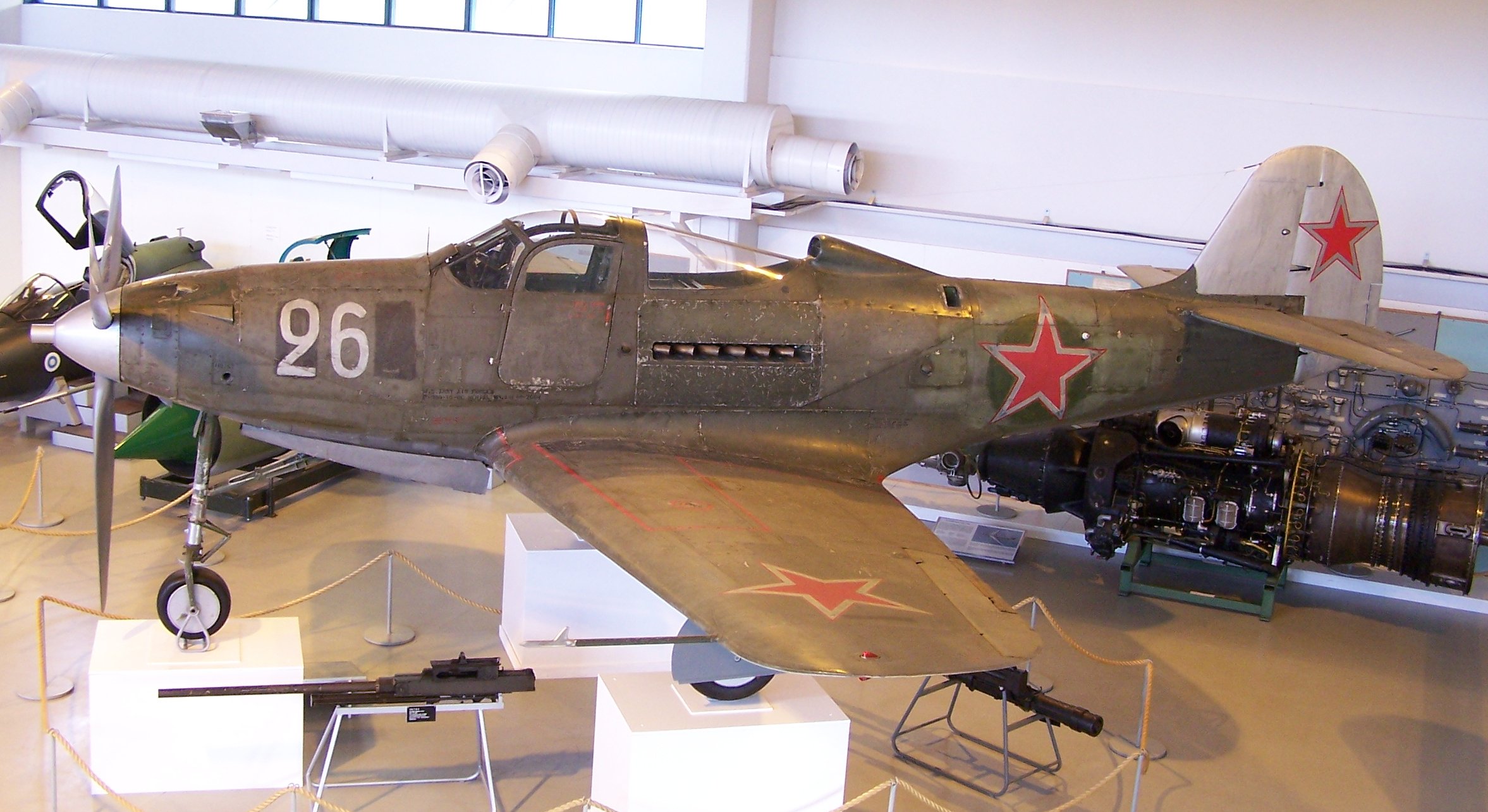
The blueprint archives are not expensive when you think that you could get 10000 blueprints for a small amount of money. The downside of having so many blueprints is finding what you need to help with your learning task. The P-51 Mustang blueprints come complete with a fully detailed drawing list which helps enormously. The P-39 blueprints are roughly sorted into categories which helps in this respect. The Fw190 and Bf109 sets are also very good but as they are in German this sometimes can be counterproductive if it is not your first language.
I am currently putting together a free random collection of a dozen or so blueprints from the various Aviation archives that will give you an introduction to real-world applications and a head start on your project. Just drop me a line at hughtechnotes@gmail.com.
The initial randomly selected files are available online here. https://www.mediafire.com/folder/iyedg37u0ckku/Blueprint+samples


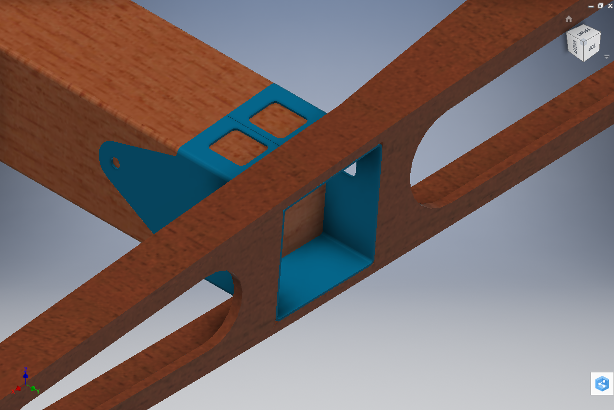


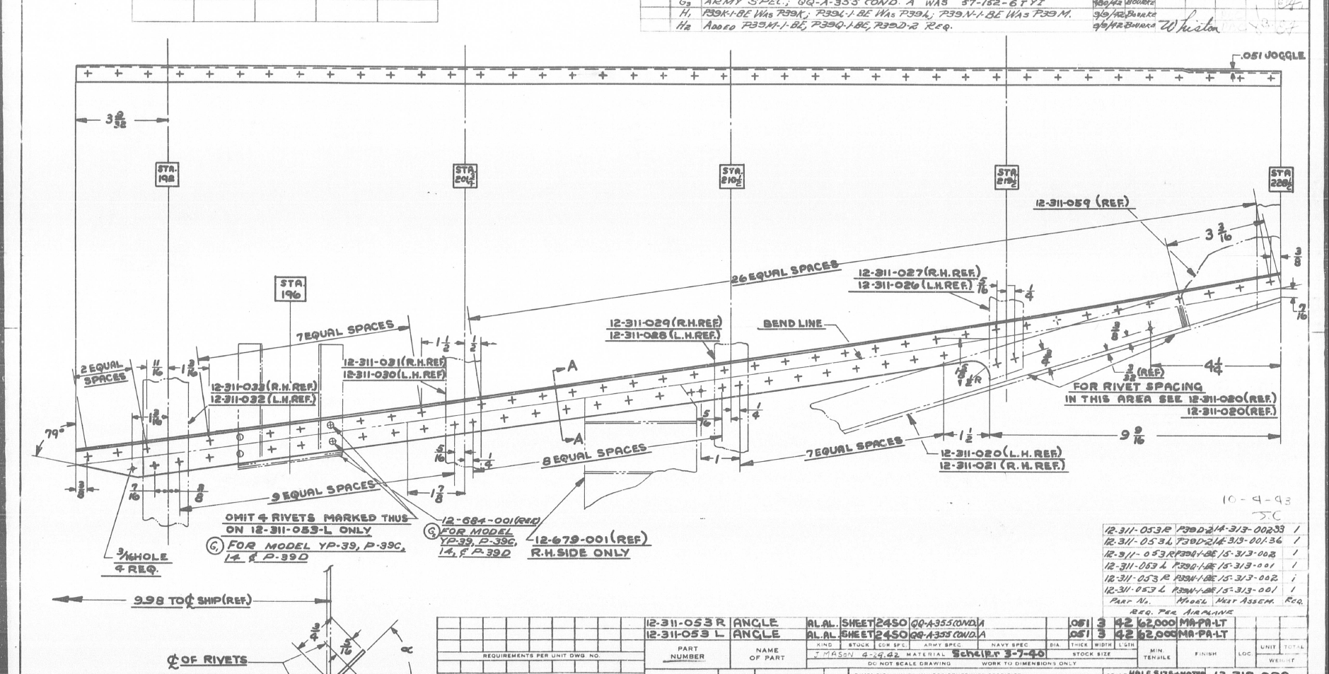


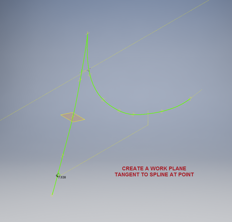
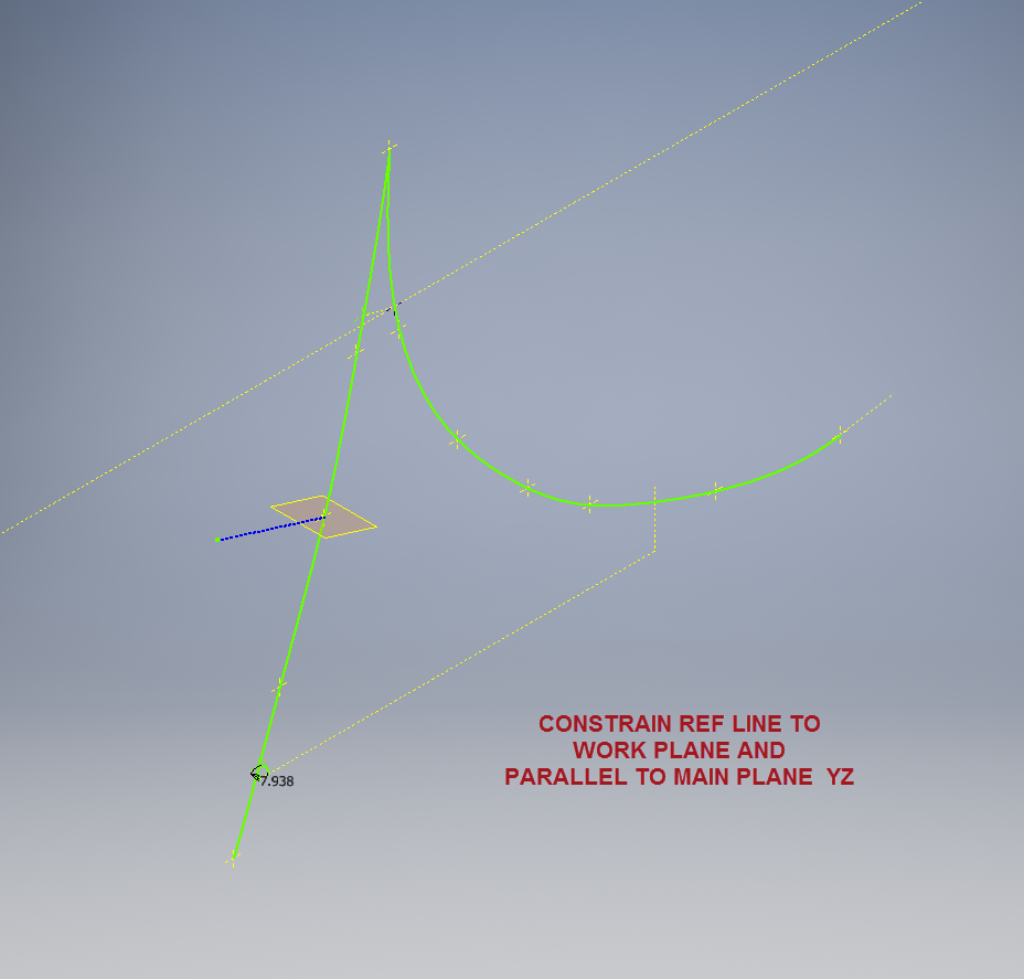


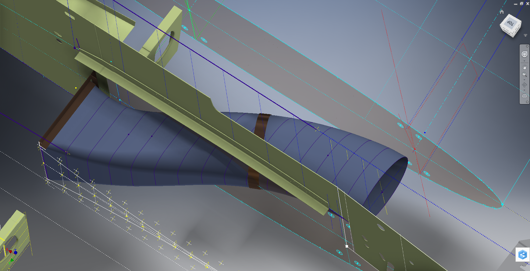


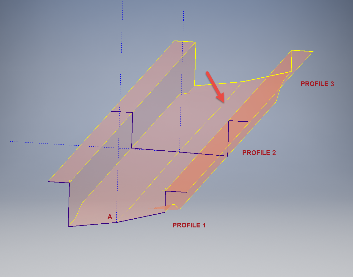 This is the lower level fuselage cross member that has a built in twist to align with the connecting frames at both ends. The model consists of 3 profiles with the 2 outer ones containing a small angular deviation in the centre at point A. Normally I would loft the profiles to create the finished surface but this projects the deviation throughout the length giving us 2 surfaces; which does not look good.


