Exploring the Republic-Ford JB-2 Thunderbug

Republic/Ford JB-2:

The Republic-Ford JB-2, also known as the Thunderbug, KGW and LTV-N-2 Loon, was an American copy of the German V-1 flying bomb.

I came across some blueprints for this and decided to develop a hyper detailed CAD model.

The blueprints are very poor quality; incidentally all of them are marked “illegible”, however, it is possible to extrapolate some key information that will provide a good accurate replica. At this stage, I am not sure exactly how far I can take this project but I shall endeavor to model every part that I can find and then take it from there.

As usual, I have all the key dimensions listed in spreadsheets for future reference. I studied the wing profiles and discovered the airfoil used is the NACA 0015. The wing construction is rather unusual in that the ribs are formed from 2 mirrored sections. As the project progresses I will explain that in more detail as an addendum to this post…so watch this space.

Update 26th Dec 2024:

Made quite good progress on this project. Still a lot of work to do, particularly on the empennage. I will take a break for a few days and post another update in a week or so.

Update 1st Jan 2025:

A few images showing the progress on this model build showing the Engine Intake, Wing construction and miscellaneous work on the Empennage including the Rudder Support.

Update 7th Jan 2025:

The horizontal stabiliser is almost finished. Notice the inclusion of the spoilers on the underside. The Aft fuselage deck has also been added. A close-up view of the Air bottles shows the surrounding supporting structure.

P-47 Ordinate Study Update

P-47 Ordinate Study Update

For most of this year, my primary focus has been the restoration project for the P-39 at Planes of Fame. That is still very much work in progress. At this stage, it is mainly the fabrication side of things, as the majority of controls have been drawn. The mounts for the Gunsight are currently being made. I hope to include some photographs of the installation in a later post.

The Gunsight was an extensive and challenging study…the drawing layout shown above was derived from a dozen or so blueprints and various manuals compiled together on one drawing. The circled dimensions are those verified from one or more sources.

During this time I have been doing some preliminary studies for the P-47. Over the last few weeks, the P-39 project demanded less of my time which has enabled me to further develop the ordinate study for the P-47.

The basic Layouts are developed for the Cowl, Fuselage, Empennage, Wings and Cockpit Enclosure. Still a lot of work to do on the details and resolve a number of queries.

One particular area of interest is the wings. As you can see a lot of work has been done on this layout which shows the Main Spars (shaded), Flaps and the leading and trailing edge profiles. The Aileron and Wing Tip is still a work in progress. The wing comprises 6 thickness variations of the S3 profile…15% at Sta 0 (Ctr aircraft), 14.2% at STA 74 (0.3 x Span), 12.3% at STA 123 (0.5 x Span), 10.5% at STA 172 (0.7 x Span), 9.2% at STA 222 (0.9 x Span) and 9.0% at Tip extent STA 246.

For the Main Spars we have the vertical dimensions coupled with the correct lines for the Flaps and Leading edge providing key important ordinate points that the rib airfoil profile should match. For the Airfoil ordinates I referenced documentation on the Republic S3 profile from the UIUC website and The NACA Technical Reports WRL-98 and WRL-159.

For The Horizontal Stabiliser we do have good information to develop a 2d plan layout including the dimensions for the Elevator to derive an accurate trailing edge. We lack sufficient depth information for any of the spars or ribs. Therefore, it is important to ensure we have the correct Stabiliser airfoil profiles.

The Republic blueprints list the airfoil ordinates at station 10.5 and station 83. These were recorded on spreadsheets and subsequently onto the CAD model. I found that the alignment for the spar positions and the 70% chord were slightly out. I reverse engineered the offset ordinate data to derive a Basic profile which I intend to use to further develop the intermediate ribs.

The first table above shows the recorded ordinate data for the airfoils at Sta 10.5 and 83. Working back from the offsets you can see the Basic Ordinates are similar but not exact. Therefore it seems logical to take the mean values from both tables to derive a workable basic profile which I can use later, shown in the middle column. The second table shows the adjusted ordinates for each profile. You may be asking what recognizable profile did Republic use for the stabilizer…again I do not know for sure. I have a parametric table setup for the more common NACA profiles used for other similar aircraft and none match.

The key dimensions for the profile relate to the 70% chord offset and the alignment with the front spar center. What I think is happening is the area from the leading edge to the 70% chord defines the surface for the Horizontal stabilizer and the curved trailing edge of the Elevator is essentially morphed to this line. What few vertical dimensions we have from several areas tend to match with this arrangement.

The cyan lines show the alignments at the front spar and the 70% chord for reference. The plan outline for the Elevator is drawn according to the known ordinate points. The second table above is designed to give me the airfoil offsets for any rib according to the chords derived from the CAD model…this is essentially the position of the measured 70% chord and is calculated to give me the actual chord length. All of this will be verified which means trawling through the many thousands of blueprints I have to find key offset data I can check against. Of course, I could use the Aircorps database for this but the many scans of this area are blacked out..the archive I have is much better quality.

I take nothing for granted with these studies and try to verify dimensional information from more than one source. I firmly believe that if we get the dimensional information correct everything else will fall into place.

As usual please get in touch with any technical queries or comments. hughtechnotes@gmail.com

Update 20th Dec 2024:

I have the basic geometry for the Horizontal Stabilizer and Elevator worked out…some detailed work is yet to be done on the Tip and the main Spars.

Technote: Rivets

Technote: Rivets:

Developing the CAD standards for Rivets has been on my to-do list for far too long..so with the progression of the P-39 cockpit instruments it has become a priority. Typically on the Bell drawings and other aircraft manufacturers’ drawings we may only have the hole sizes noted, the rivet designation or information pertaining to the same but unreadable. Also occasionally even when we do have the hole sizes and the rivet designation often we don’t have the length required.

Something needed to be done to make this task a lot easier, particularly when you have instrument panels that incorporate many different types and sizes of rivets.

The first part of the process is to create several parts for the various types of rivets; which at the moment are listing the most common sizes I need right now. You will notice that the Rivet Name does not include the material type as doing so would require an extraordinarily large table of data. So the name is simplified to make this task easier to correlate but also because the priority at this time is dimensional correctness for rivet type, diameter, hole sizes and rivet length. At some stage, I will invest some time into deriving the various information sources to correctly name the rivets according to the AN and MS standards.

To complement the CAD iParts I also have a few spreadsheets listing key parameters and fabrication criteria.

The above tables are self-explanatory with the inclusion of a designation for a Bell Standard Rivet 35R1. I have actually found dimensional information for this type which I will include in the CAD library. This is where things get interesting because of the scarcity of historical components that may no longer be available, it may be necessary to find suitable alternatives.

You will notice that the Rivet Grip tables are in inches and mm…as I tend to work using metric mm templates (although the dimensions are input as inches) it makes it easier to measure the material thicknesses in mm and determine from that the rivet length. There is a technote somewhere on my blog that describes the process of inputting inch dimensions in metric mm templated models.

This will be an invaluable asset moving forward with the cockpit rebuild on the P-39. For example where there are issues with the legibility of key information on the Bell assembly drawings I can refer to other connecting part drawings that may only have hole diameters but will be sufficient to determine the correct rivet type and size.

This is very much a work in progress and will be updated as needed.

Update: 28th August 2024:

I have updated the Rivet CAD files which now include AN426, AN430, AN442, AN470 and of course the Bell standard 35R1.

All Rivet CAD data files (iParts) are now included in the CAD Standard library (see CAD resource tab for further details) along with original spreadsheets of Rivet Grip and general details.

My Project Plans For 2024

My Project Plans For 2024:

The primary project for 2024 will be the F4F/FM2 Wildcat development. I aim to have a highly detailed structural model at either 1:10 or 1:15 scale 3D printed by the end of the year. Due to the requisite accuracies, this will be MSLA resin printed. My work is simply to produce the most dimensionally accurate aviation models in 3D CAD and accordingly fully documented.

I have recently started building the Landing Gear for the F4F which is shown below; this is the axle part # SP597. The image on the right is the forged model which is derived for machining into the part on the left.

Another example is again the Landing Gear; this time the Lower Drag mechanism. Through exhaustive research, I can go from an almost illegible blueprint to a clear sketch on the right. This is why I do what I do.

The other aircraft I will be revisiting is the P-38 Lightning as some aspects of that project warrant further research. For both aircraft, I will be visiting the collections at RAF Cosford and Shuttleworth later this year to hopefully fill in some of the blanks.

The projects will also involve updating my blueprint archives to make it easier to search for drawings initially by renumbering all 8000 plus drawings inclusive of drawing numbers. I have already started this for the F4F Wildcat which was helped enormously by some clever folks on YouTube. https://youtu.be/I9ffWZ_Bt6o?si=OEog79e-XaRUZz7K

The first portion of the numbering sequence is the original scan reference followed by the actual drawing number. The An Parts library will also be updated with additional conversions for use in other CAD systems.

2024 will no doubt be a busy year for me with the 1:10 scale printed model being the biggest challenge.

I hope that you will continue to support my endeavors throughout this year. Happy New Year.

Technote: 3d Modeling to Clarify Assemblies

Technote: 3d Modeling to Clarify Assemblies

Interspersed throughout this blog are many examples of Technotes describing techniques and problem-solving primarily for 3d CAD modeling. Many of the part examples shown are actually created to address another major issue with Assemblies.

It is not uncommon for the assembly drawings to be either unclear or simply void of key information that would help establish relationships between sub-assemblies or parts. In many examples, it is simply that the reproduction of the microfilm prints is not sufficiently clear to comprehend what is going on, otherwise the omission of basic dimensional relationships.

For the P-51 Mustang, I fully developed the rear Landing Gear mechanisms to clarify what the heck was going on as the NAA Assembly drawings details were obscured.

It is too often the case that general assembly drawings tend to be nothing more than an illustrated parts list with few key dimensions that define locations or relationships between the individual parts. This is also true for many of the sub-assemblies. For the P-51 Tailwheel sub-assemblies, I also developed 2D detail drawings showing key dimensions and parts lists. Ideally, I would have developed presentation drawings showing the exploded views of each of these assemblies to provide further clarification…perhaps a project for the future.

In the case of the P-38 Lightning, I have developed the Landing Gear assemblies to check the ordinate dimensions… which by the way are good. I now have the Coolant Radiator assembly which was again developed to check ordinate data but also for the same reasons as I did the models for the P-51 Tailwheel.

Typically the general assembly pictorially shows the sub-assemblies without any key dimensional information to define the location or part relationships and similarly, the sub-assembly for the clamp is not that much better. This is important stuff as occasionally they are the only reference material we have to help define ordinate data that is missing from the archive blueprints.

The Coolant Radiator is compromised by wrong dimensions as well…the top clamp cover, for example, had dimensions for the connection to the rod with the part drawing showing conflicting locations for different views of the same part.

The problem here is the connecting bracket item 224045 cannot possibly be 1″ from the edge of the cover plate whilst the overall dimension of 6 7/16″ prevails. I initially had located that bracket at 1 inch which seemed to be correct at the time because it fitted the part profile but when I introduced this into the assembly drawing it would not correctly align with the radiator. However, when I revised this using the 6 7/16 inch dimension it worked. That connecting part also caused more problems because the face of the part is machined 1/64″ which is not taken into account when positioning the part in the assembly.

Accumulatively this resulted in the overall width of the clamp assembly being smaller than it should be. This only came to light when I modeled the 234183 almost inconspicuous part as the stated dimension of 9.25″ did not fit with my initial layout..my first thought was this may just be an oversight but when I tried to align the main support frame (in gray) it did not align correctly. I went through everything and realized that the machined face of the corner parts connecting to the rod as shown may not have been taken into account and when removed the alignment was better and the 9.25-inch dimension on the strap was now correct. I am convinced that there should be spacers/washers between those connecting parts but this is not apparent on the assembly drawings. There remains a small discrepancy of 0.8mm which I am unable to account for….as this mainly relates to a clamp mechanism that will be compressed on assembly it was probably not deemed important but when you are trying to establish baseline dimensions it is actually very important.

The Part catalogs generally are your first port of call when developing these assemblies but they do not contain the key dimensions you need so these 3d CAD models are essential to achieve clarity. Incidentally, while we are talking about part catalogs it is important to understand what parts belong to which version of the aircraft. For the P-38 Lightning, the first few pages list the version and serial numbers which in turn are listed elsewhere where a Usage code is assigned. In this case the “e” is essentially the P-38H and the “bv” is the P-38J. The P-38 Part catalogs tend to show the version variations on one page; which can be really daunting; whereas others may show the version differences on separate pages…so you have to be attentive.

As I mentioned at the beginning of this article the main purpose of these assembly models is to achieve clarity and to check dimensional relationships. I think this is very important stuff that would certainly benefit from exploded views in conjunction with clear assembly 2d drawings.

As usual, get in touch if you can help support my work. hughtechnotes@gmail.com

P-38 Lightning: Ord/Dimensions Study Complete

P-38 Lightning: Ord/Dimensions Study Complete:

The P-38 Lightning Ordinate/Dimension study is now finished after 7 long months. Initially, I had planned on doing this study in 3 months; working night and day; but alas due to the complexity of this aircraft this drifted into 7 months.

All areas of the aircraft have been studied, and modeled with all known, and henceforth many previously unknown dimensions collected and recorded in a comprehensive spreadsheet.

All bulkhead and rib profiles are generated for the wings, ailerons, elevators, horizontal and vertical stabilizers, rudder, fore and aft booms, fuselage, cockpit, and flaps. The latter was a challenge as the Lockheed drawings were unclear about the relationship of the flaps to the wings…however, after some research, I was able to resolve this issue to determine the exact positions of the Wing and Center Section flaps. The flap details are fully dimensioned now on 2d Acad drawings…that was the last hurdle.

Further to the Ordinate study I also have full 3d Cad models for the Nose and main Landing Gear Assemblies.

For further details get in touch: hughtechnotes@gmail.com

Technote: P-38 Lightning Wing Tip

Technote: P-38 Lightning Wing Tip Development:

Developing this wing tip turned out to be more complex than I originally thought it would be. Because the model required a few interesting techniques I figured it is worthy of a quick technote that hopefully will assist others.

First, off the bat, you will probably have noticed the center partition which came about as a consequence of the development process. I will try to explain how this transpired…read on for more details.

What we have is essentially one main rib profile at Station 289 and 2 others towards the tip which you would normally just loft to achieve the finished surface assuming that the required outline guide rails were included in the initial data set. Actually in this case we didn’t have those curved outlines as a 3d profile only a 2d outline on the plan view. Even with the guide rails in place just lofting the full rib profiles did not work due to the continuity of the rails in a circular manner that prevented a successful loft.

By the way, the circular guide rails at “A” and “B” were generated as intersection curves using a side profile (top right in the background) and the plan profile to derive the resulting intersection lines. I initially wanted to extrude the 2d plan profile and build a 3d curve on the face of the surface but I was unable to apply a tangent constraint to align with the Leading and Trailing edges…so my only option was a 3d intersection curve.

Realizing that a full rib profile loft was not achievable I decided to fill each rib profile with a patch surface and then split the surface at the main beam intersection, which incidentally is perpendicular to the ribs. So this gave me a patchwork of surfaces fore and aft that I used as surface profiles and lofted each section as shown using the guide rails at “A” and “B” and the center rail at “C”…this created the partition I mentioned in the beginning.

Once the main fore and aft sections were modeled I then proceeded with the extreme tip which was simply a case of again adding a surface patch to the small projecting profile in the center and lofting the surfaces separately as before. Occasionally when you have problems with lofting it often helps to break it down into more manageable chunks.

Accuracy is extremely important to ensure a good surface finish with no small deviations or folds. So I checked the coordinates of each profile mathematically and adjusted the dimensions accordingly for the top surface.

The rib profile at 1,2 and 3 was adjusted to the new coordinates for the top line only but making sure that the LE and TE were tangential to the mathematically generated curves shown in red. These end ribs are actually modified profiles according to the tabulated information on the Lockheed drawings…apparently, the profile at the wing tips is based on a NACA 4412 airfoil but when I generated a 4412 it did not match…I am not sure why but it is something that warrants further research. As I did not have the mathematical formulas or guidance on hand to check the lower profiles I accepted what information was contained in the tables…mind you I could have generated a line equation from this information in Excel. Incidentally, all the wing ribs were checked mathematically with the resulting dimensions used to generate the profiles throughout.

The first image shows a sample of the modified values at Rib station 289, highlighted in green alongside the normal profile on the left. The second image shows the explanation of how the main wing rib profiles were generated. All this information is included in the CAD/ordinate dataset. Also on the second image, you can see a typical rib profile extracted from the Lockheed drawings which shows the 0% chord is actually set back from the Leading Edge, which is most unusual. This created a few problems because now I had to determine from the CAD model the Actual Leading Edge before I could define the curved guide rails for generating the wing tip lofts.

This all may seem overkill and a lot more work than one would expect just to build a wing tip but the Inventor Loft command requires absolute precision when lofting with guide rails so it pays dividends to mathematically check everything where possible to ensure successful lofting. I shall update the CAD/Ordinate dataset over the next few days to include this new data.

.

.

.

Technote: P-38 Lightning Coolant Rad.

Technote: P-38 Lightning Coolant Rad Scoop.

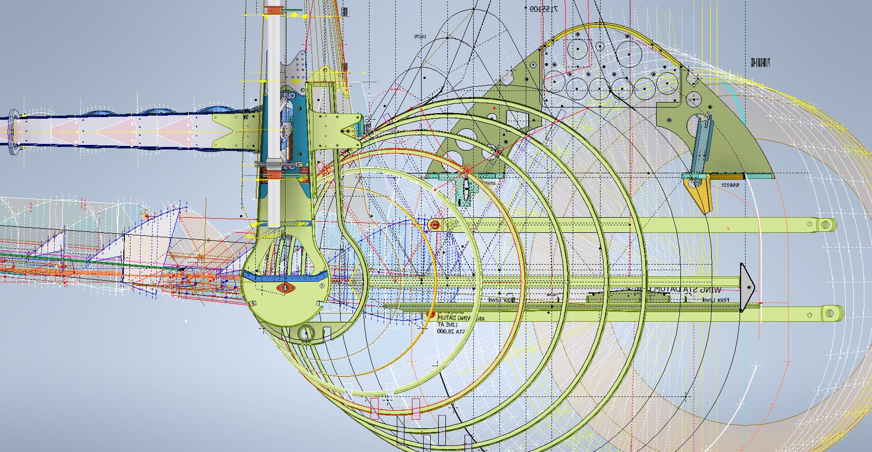
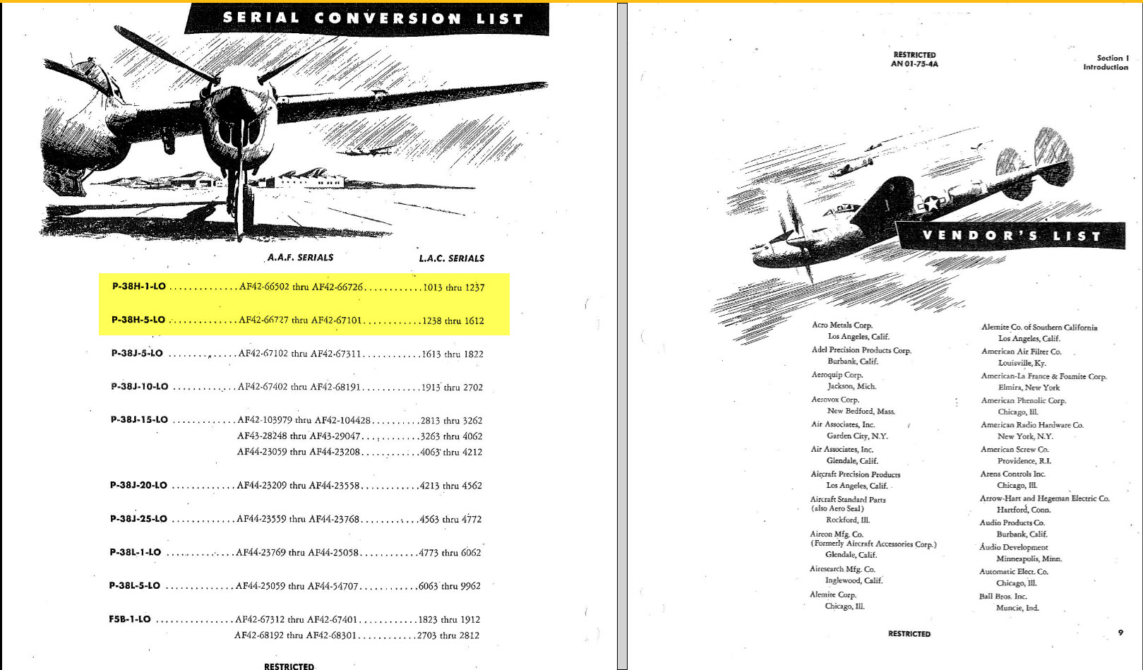
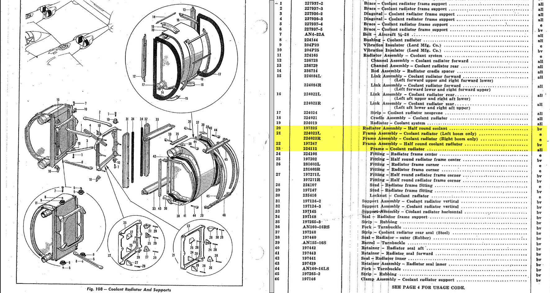
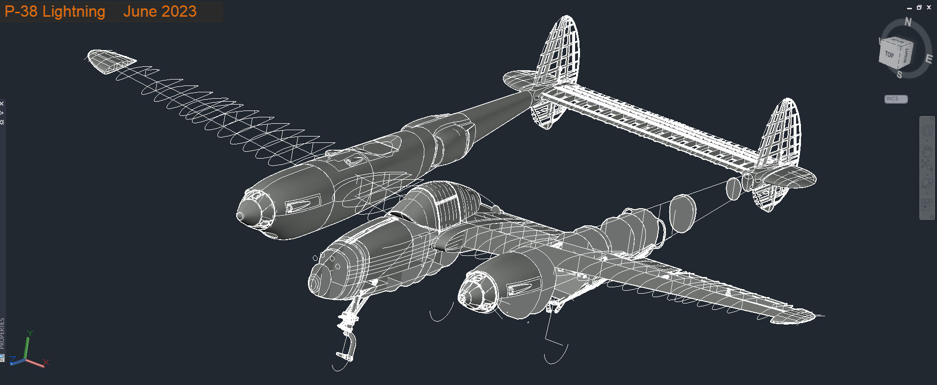
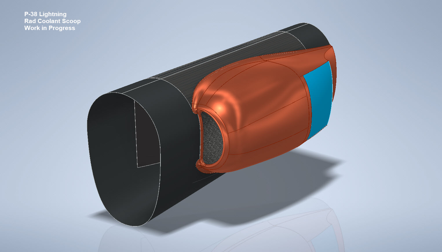
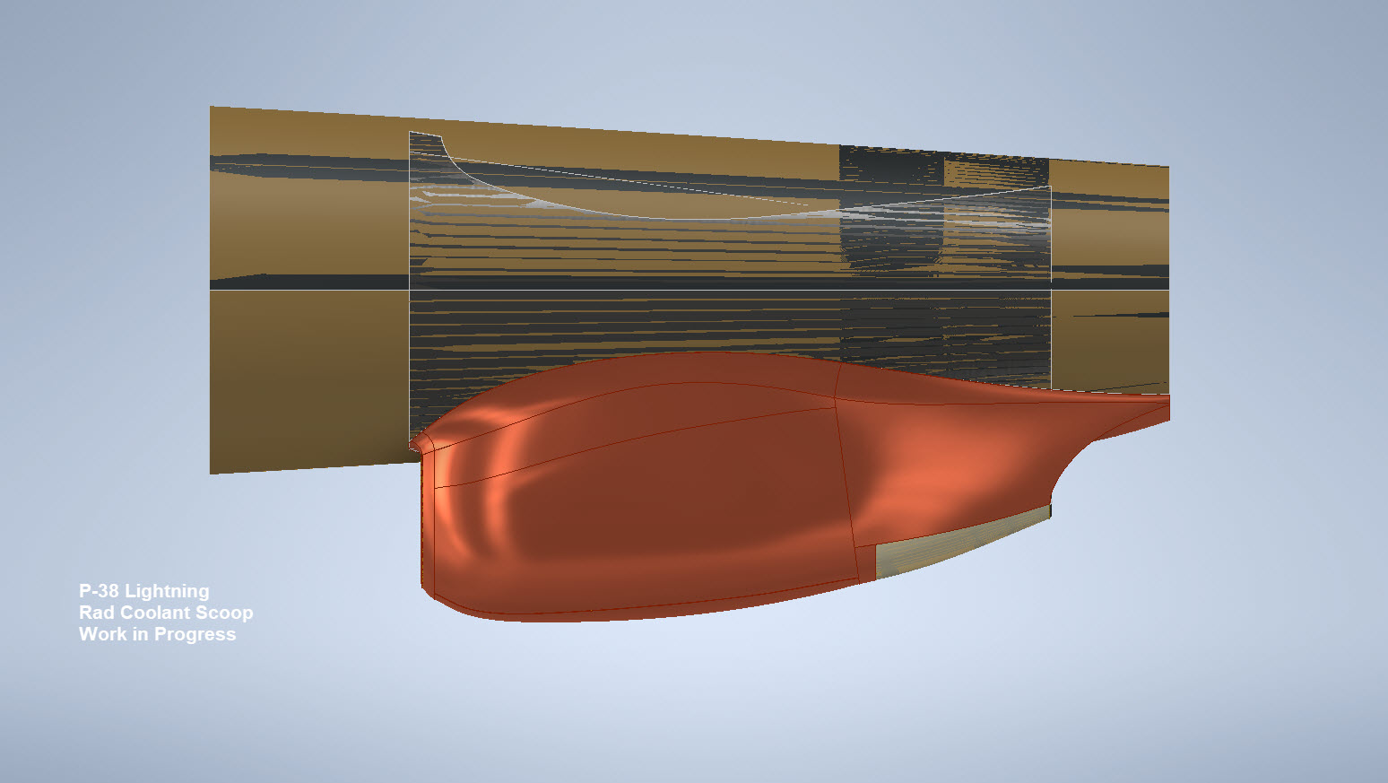
My latest endeavour is to model the Coolant Rad Scoop and later on the Engine Cowl for the P-38J. This is the Coolant Rad Scoop which was very challenging. There is not a lot of dimensional information on the drawings for this scoop which is larger and wider than the previous versions.

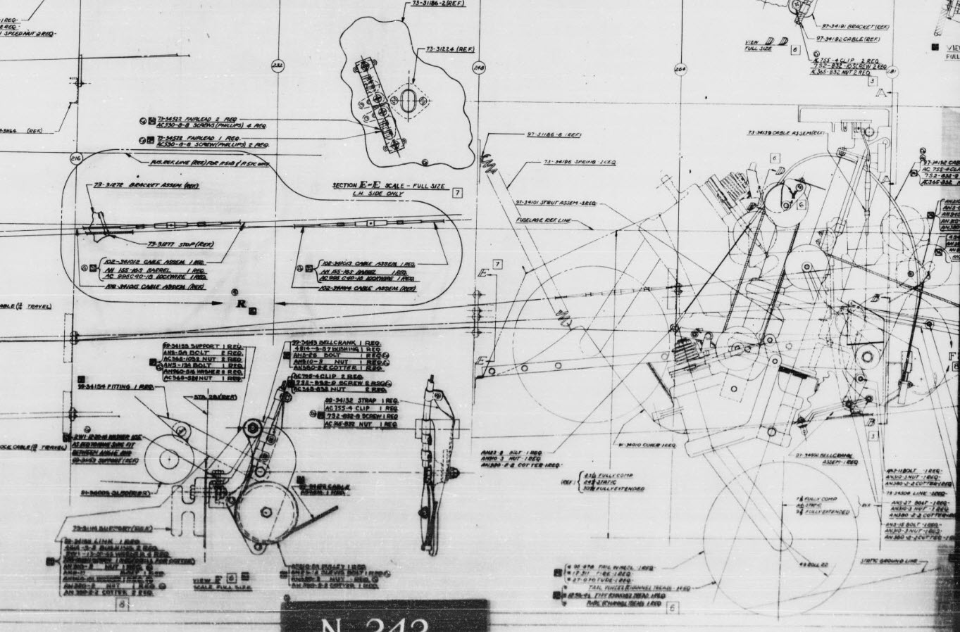
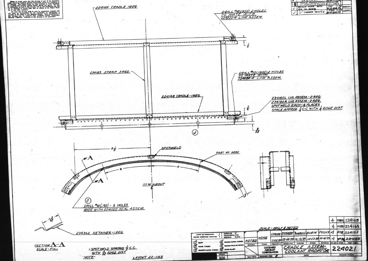
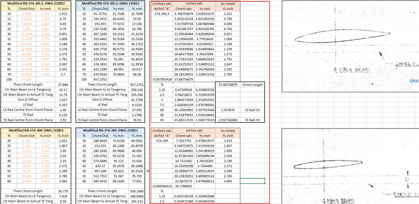
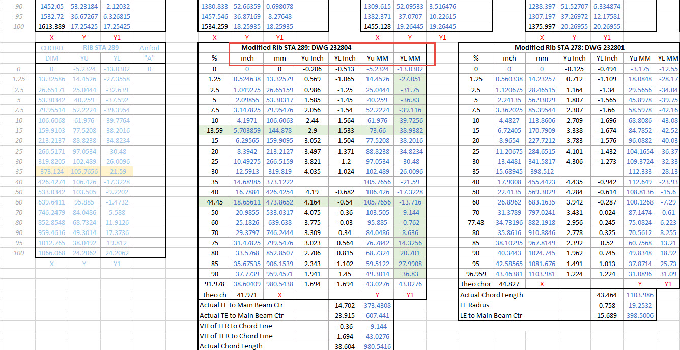
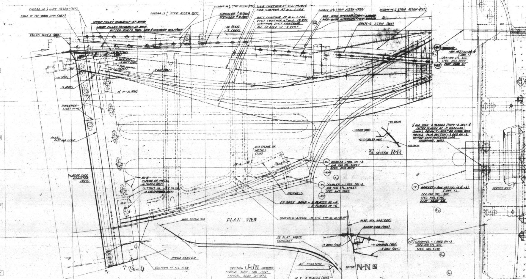
I would say this finished model is probably as close to the real thing as I can get given the complete lack of decent information. The Lockheed drawings for this scoop are largely predicated on known ordinate information which unfortunately is not available in the microfilm archives. What we do have though is a 5″ grid overlaid on the drawings…this in itself is a puzzle because what they have done is divide the drawings into 5″ square grids which may or not be relevant to end views and cross sections…so using the grid as a positional aid is inconsistent.

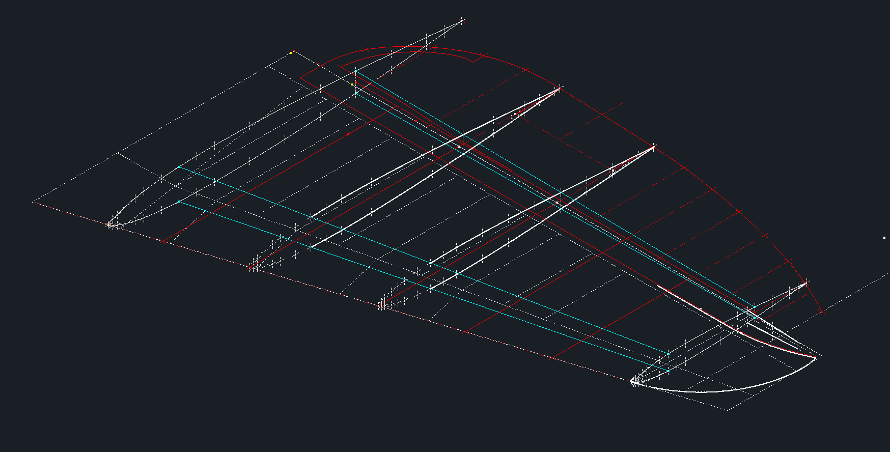
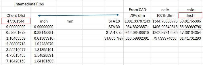
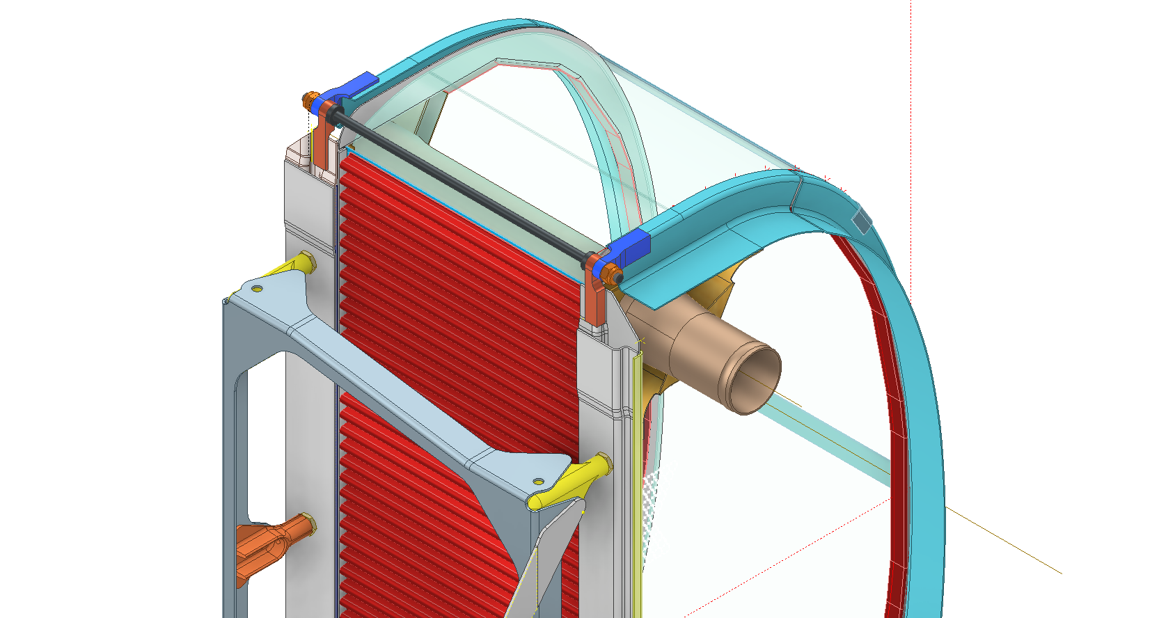
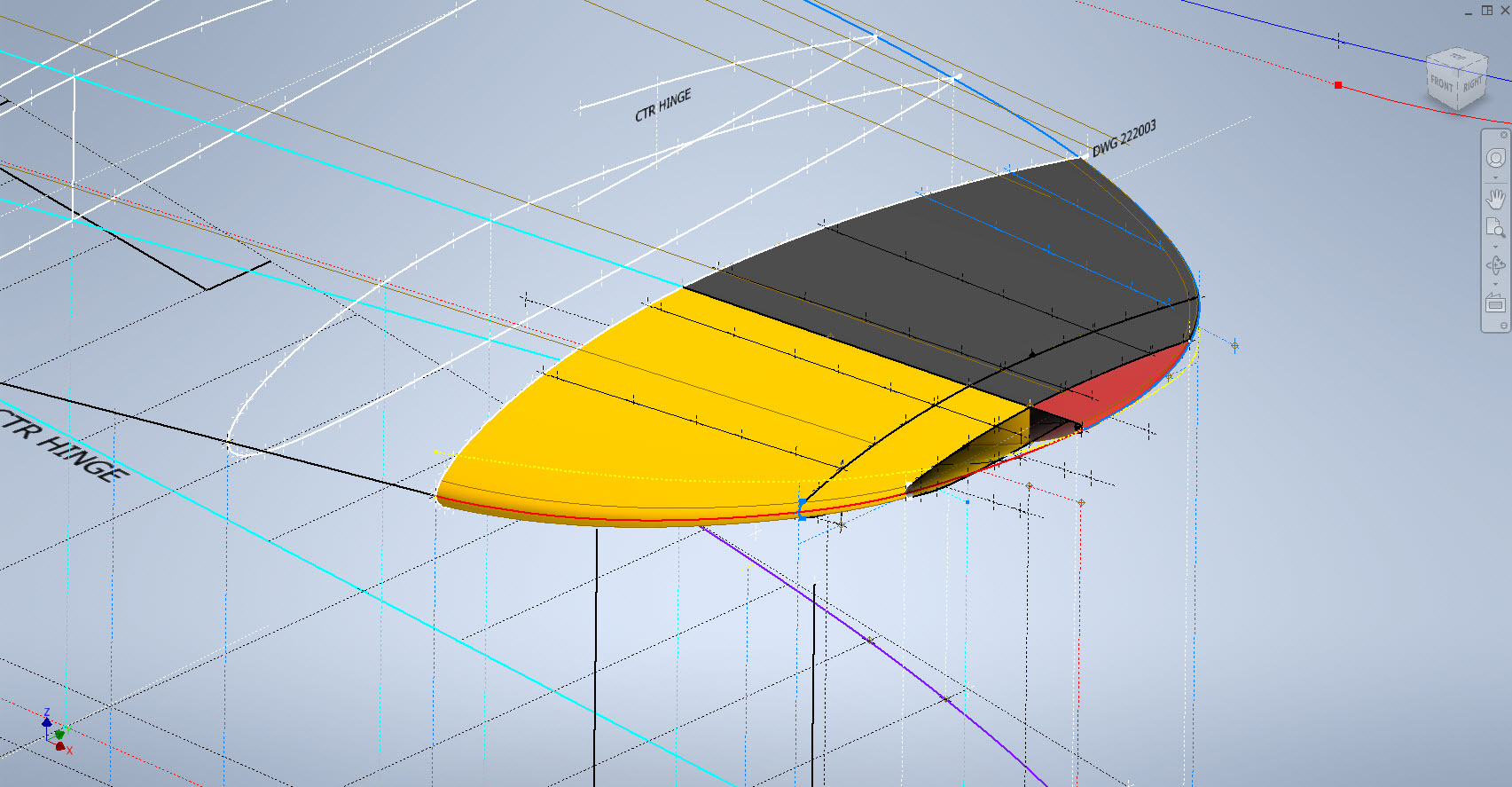
There are of course good references to the Stations which help a lot. One of the key decisions is interpreting what is an arc radius and what is a spline…I made some decisions on this early on and opted for a circular profile of the inlet and the second frame and beyond that a spline with ordinates at every 5″. It was a close match to the profiles on the drawings but if it is what the designer intended I have no idea.

Scaling digital copies of the drawings and using them as a background for building CAD models is not something I am keen on doing. I did write an article way back on scaling in X and Y directions…I shall get the link and post it here.

Fortunately, this model is being used for a CFD study so microdimensional accuracy isn’t required. The final model is what is best described as a close approximation…I don’t do close approximations…this is the exception…though I may have to undergo a similar exercise for the engine cowl!!

Inventor is probably not the best CAD product for serious surface modelling that is dependent on dimensional information. Sure they have the usual lofts, patches, sweeps and of course freeform. Freeform is a very organic feature that can work with other surface-derived types but it does not regenerate when that sketch geometry changes; a serious omission which I understand is on the Autodesk to-do list. Even the standard Loft feature is flawed.

For example, if you have 2 sketches that contain concentric profiles (like the ends of a tube) this cannot be lofted in Inventor…it just cannot be done. The other issue I have with this command is when you loft using guidelines or rails. No matter how precise your modelling there will be times this will not work…so you redo the lines over and over again…double checking everything and eventually it may work. Yet if you use the sweep command using the same profiles and rails it will work…so there are some serious issues with lofting that Autodesk really need to fix.

I think Autodesk need to take a leaf out of the Dassault workbook…I believe it was in Solidworks 2010 that Dassault decided to revise all the commands and features within the product…resolving glitches, adding functionality to existing functions and generally cleaning up the product. The main fear of the media at that time was whether there was enough to tempt users to upgrade…that was a stupid concern if a product is better and everything works as it should of course that is an absolute no-brainer, folks will upgrade and they did.

Even though Inventor has a number of glitches, I quite like the product and it is generally rather good but I do think it could be a lot better. When something does not work as it should then you can spend hours just developing workarounds to achieve the end result…time for a product cleanup.

I actually prefer Solidworks but Dassault does themselves no favours when it comes to product accessibility. You can’t just download a 30-day evaluation copy whereas Autodesk has a better approach with accessibility to their products. In fact, to get a 30-day evaluation of Solidworks you have to sit through a meeting with their sales rep and only then will they load it onto your computer for you…this is a real pain that you can’t just go online and download a copy. They do have an online access portal but for folks like me, that is not convenient. I don’t have time for sales reps, all I would want to do is buy online and download without the sales crap…you can buy Autodesk products online but not Dassault.

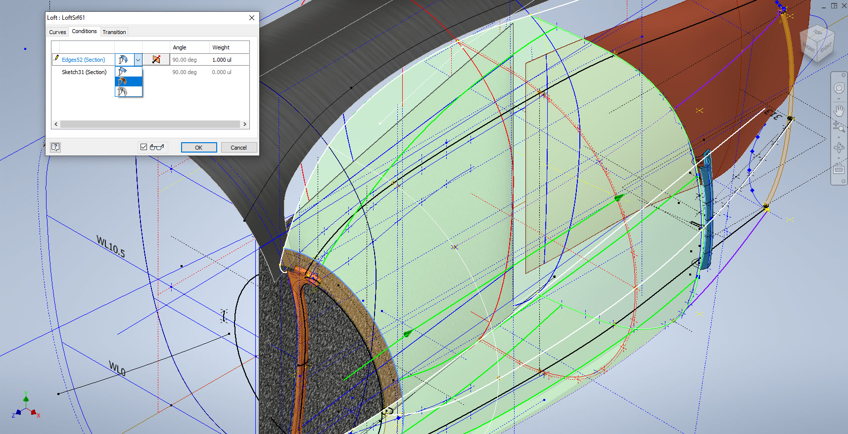
Getting back on the subject, what I wanted to mention is surface modelling. Generally, there are a few conditions for generating surfaces with Direction, Tangency or G2. If you are lofting or creating a sweep from a sketch you won’t have the latter 2 options but if you use a surface edge as a base for a loft you will get Tangent or G2 options. I like the option of G2 but comes with restrictions…it can cause problems with applying fillets (particular variable fillets) and surface offsets..so if you plan to do these late on in the model development stick to tangency. Variable fillets will not give you continuity with G2 surfaces.

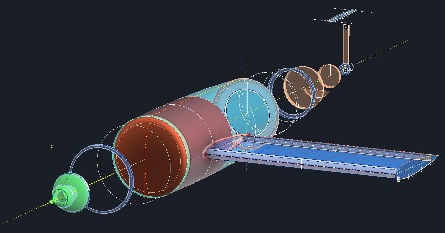
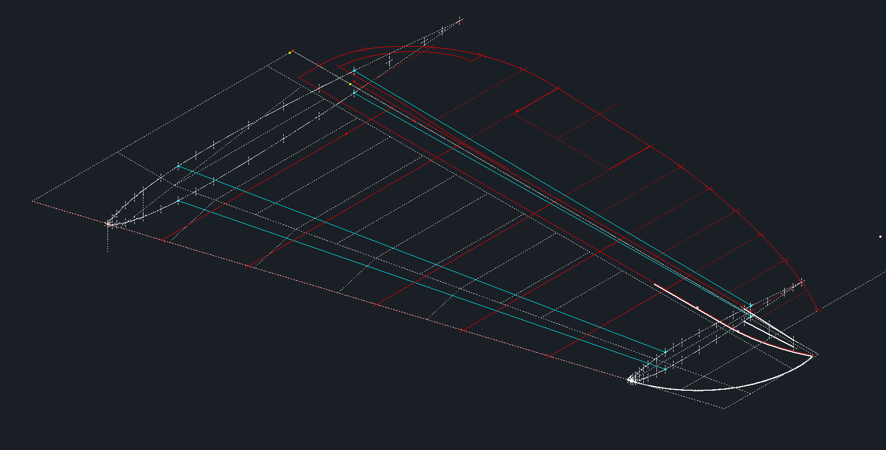
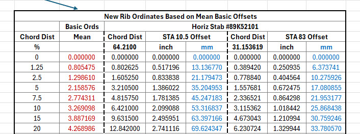
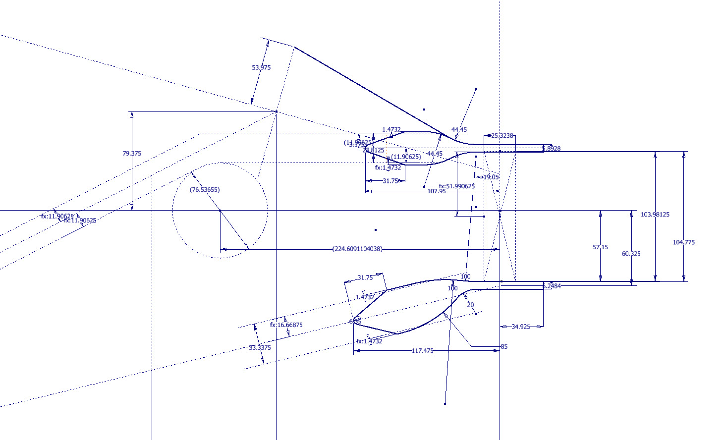
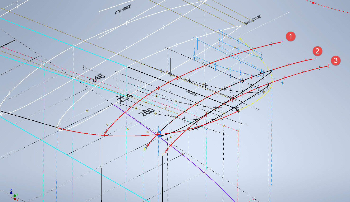
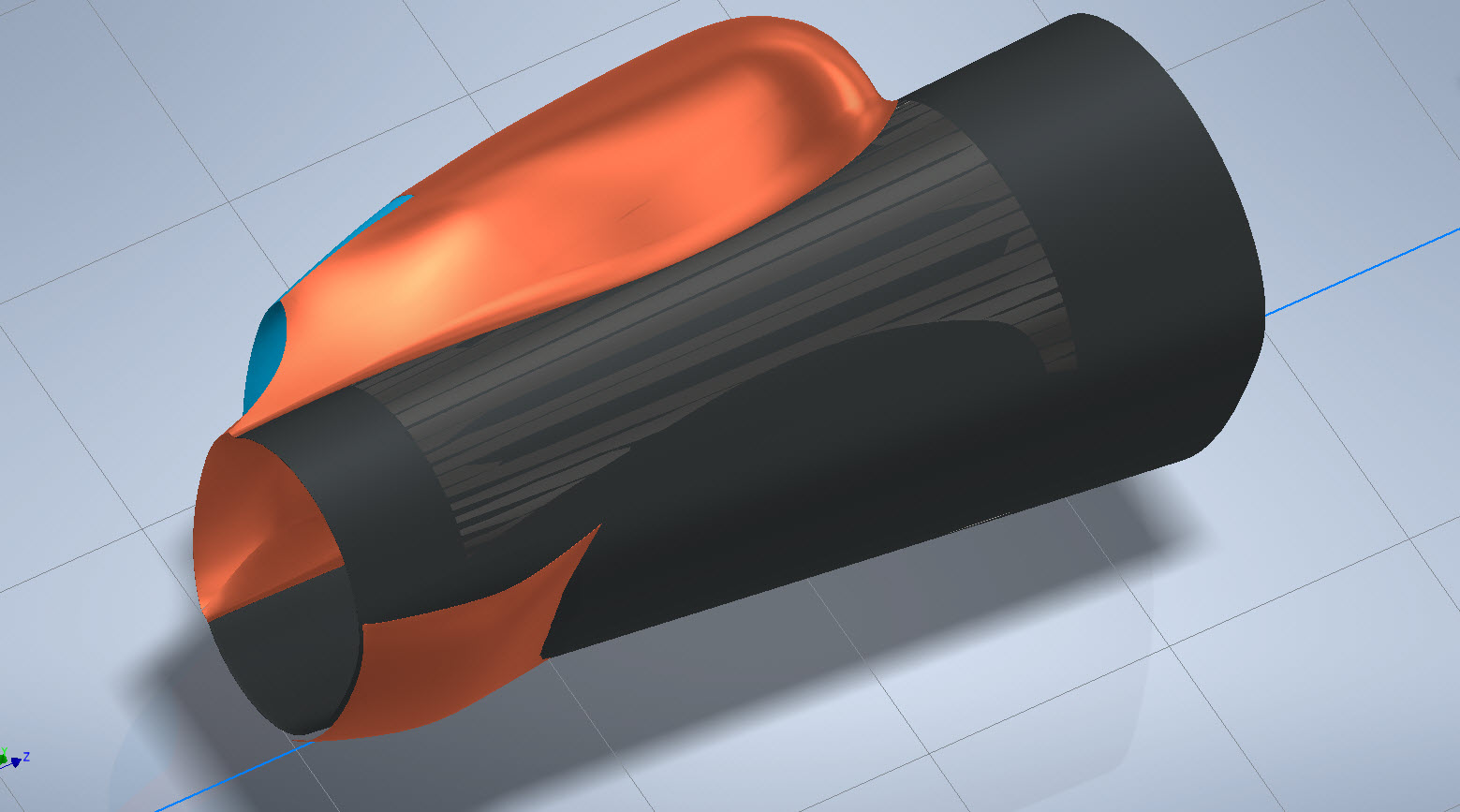
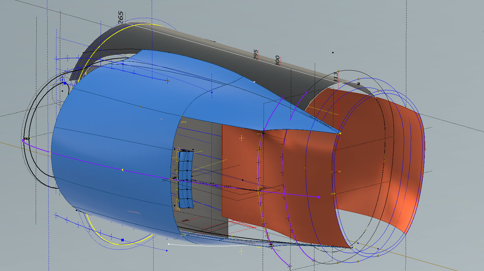
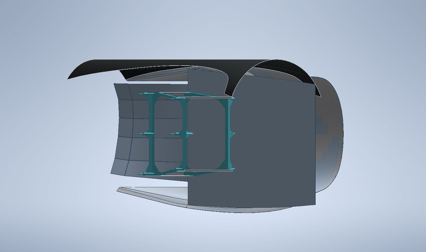
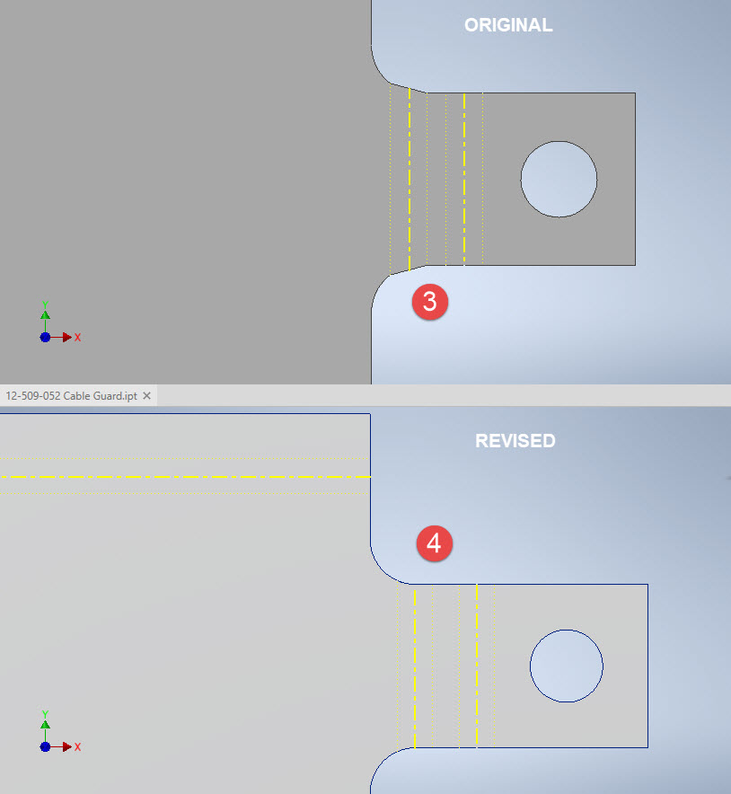
When using guidelines or rails to control the curvature of a surface loft please consider using them judiciously. As I mentioned in the previous article overuse of constraining elements can create problems with the eventual surface generated. In the first image above I have several guidelines drawn but only a few have been selected…this gives you options so that can pick and choose between the various guidelines to see how the eventual surface evolves so it is worthwhile spending the extra time having these available…it does help.

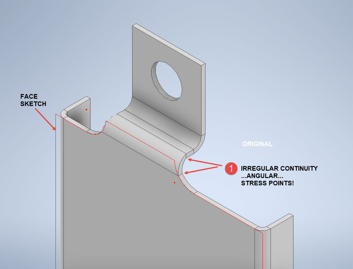
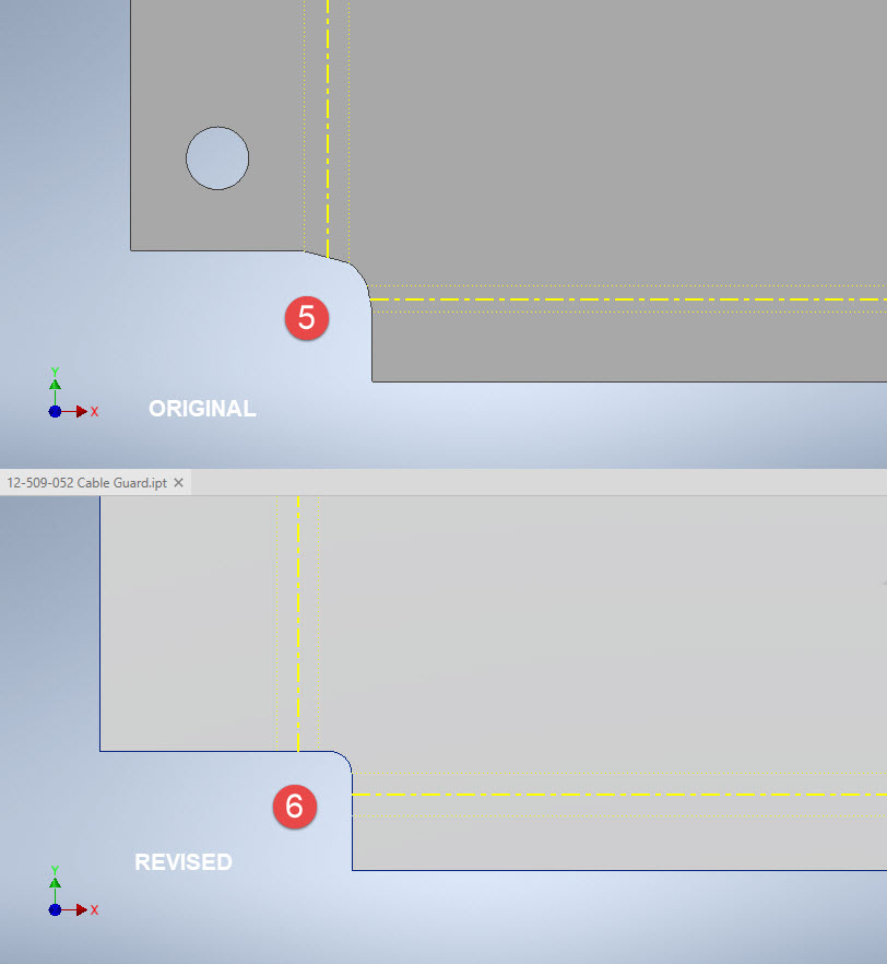
When you do run into problems with surface modelling using Lofts or Sweeps occasionally it helps if you delete that surface and replace it with a Fill Patch…the reason for this is that you have more control over each edge of a surface patch that you would not otherwise have with those features.

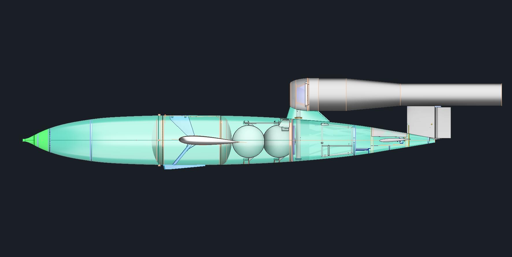
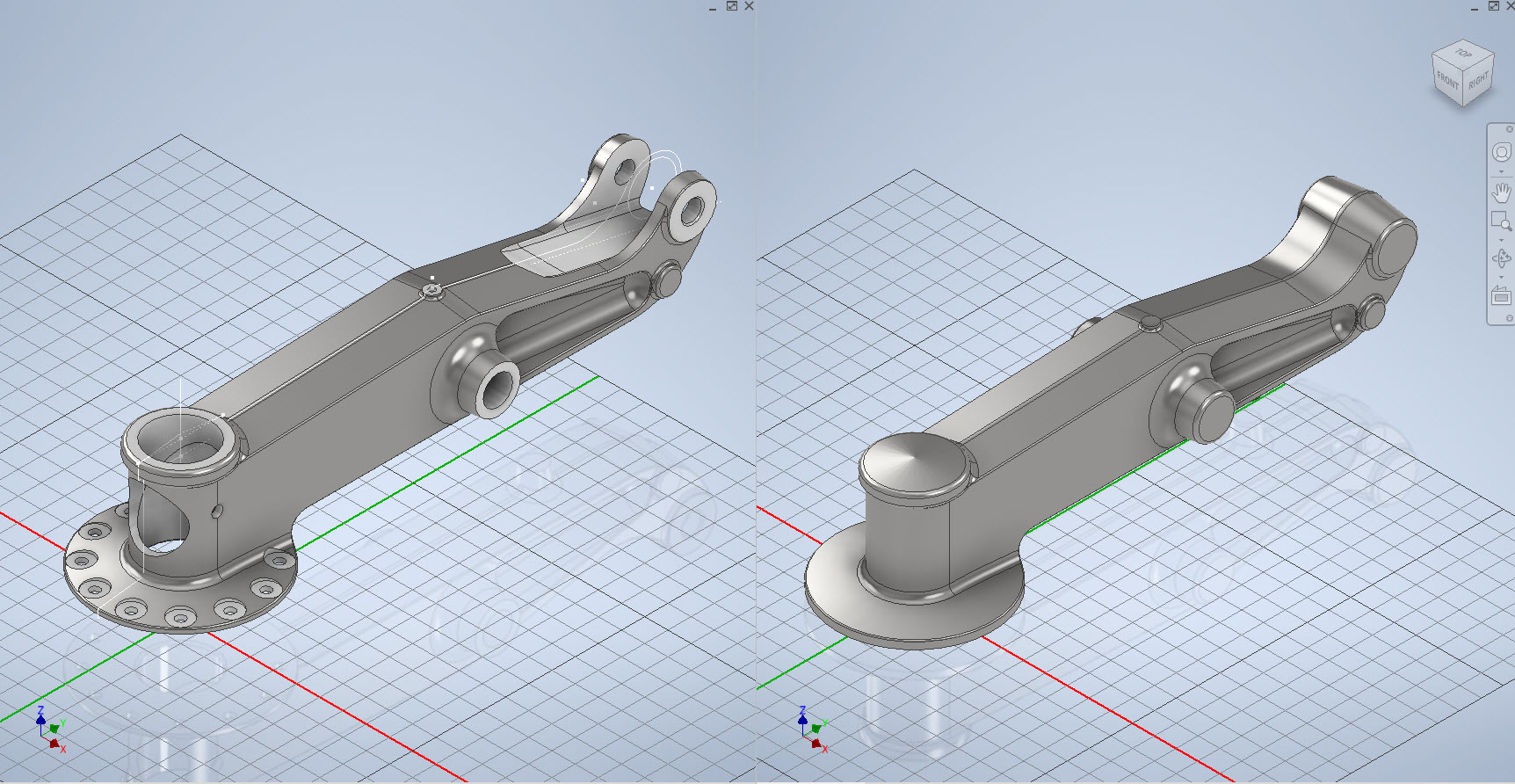
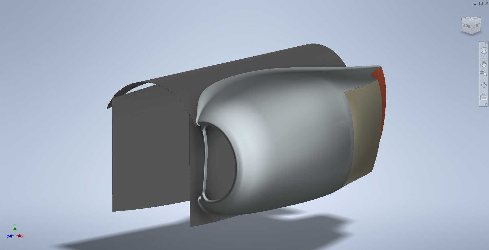
The Scoop actually turned out quite well…it was a frustrating journey to get to this point but it is worth it.

Update 20th Oct 2022:

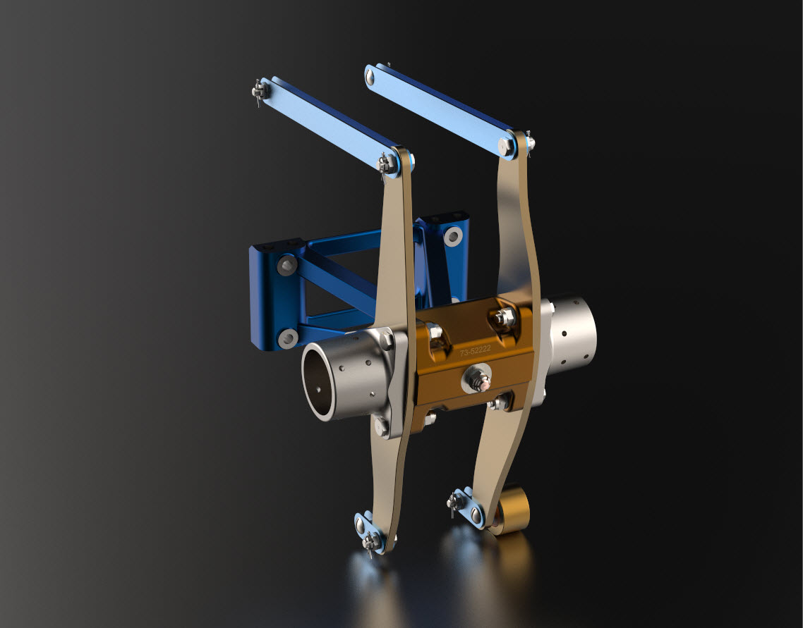
I decided that it would be prudent to also develop the earlier variant Coolant Rad Scoop for the P-38 D, G, and H models.

.

.

.

Technote: Sheetmetal; Avoid Bend Stress Points

Technote: Sheetmetal; Avoid Bend Stress Points:

This is a sheet metal part for the P-39 Airacobra (#12-509-052) sent to me by a fellow enthusiast for comment. Before I get immersed in discussion on this subject I would just say that this part is a cable cover that is unlikely to be under any substantial stress and thus would probably be fine as modelled.

The part comprises 2 tabs, one on the top and one on the bottom. It is the fillet radius that I will focus on. The first bend is offset from the edge of the plate. The drawing specifies a 5/32″ (4mm) radius for the fillets at the intersection of the top tab and the main body which overlaps the sheet metal bend. The originator has taken this literally and attempted to create a finished fillet of 5/32″.

I suspect that the drawing is actually referring to a 5/32″ radius as it would be for the developed flat pattern because doing so otherwise; due to the bend being offset as illustrated on the cad model; this introduces stress points.

The images show the irregular continuity which creates angular edges that essentially become focussed stress points. It is often best to try to achieve smooth continuity both for bending purposes and of course when in use. What they did was sketch a face profile; which included the specified radius (#1)and then proceeded to adopt the standard commands to build the flanges. Technically it is not wrong but as the manufacturer’s drawing does not contain a developed flat pattern it is often misinterpreted…the radius should perhaps be applied to the pattern before bending.

Similarly, at the bottom tab, we also have irregular continuity as shown at #2.

I rebuilt this model to address these issues and you can see how a small change in modelling technique can obviate some of these issues.

The images show the developed pattern with the original cad model on the top and the new version on the bottom. At #3 the outline of the tab would be difficult to cut with the small taper before the fillet, whereas the lower profile at #4 is easier to cut with no stress points. Similarly for the base tab at #5 and #6. I should note that the bottom tab radius is not specified so I opted for the default minimum which fits nicely before the bend lines.

There are several ways to do this with the easiest being accomplished by using the Unfold command on a square flange and then applying the fillet before refolding. The option I have used here is first to draw an extended flange as part of the initial face sketch, create the first part of the model as a Face then apply the 5/32″ fillet before bending along a predetermined bend line sketch.

The sketched tab outline is a lot bigger than is required which of course can be trimmed once the tab is complete. You can see the extents of the tab on the initial sketch…you only need to add a plane at that point to trim. The resulting fillet is a smooth continuity with no obvious stress points.

Understandably the designers wished to increase the amount of material at the bend to maximise strength so it is advised to try to achieve those goals. As I said before, for a cover like this it is probably not too critical if we only applied a small fillet but for framing and structural elements, it may be critical.

One quick note on the 2 vertical flanges…the drawing specified an internal radius of 5/32″ which to be honest is unworkable as the resulting bend would overlap the bottom tab…in this case, I opted for the minimum specified.

At the end of the day, it is down to the interpretation of the designer intent. For the majority of sheet-metal drawings, they often do not include developed flat patterns but may contain information that is actually applicable to the flat pattern and not necessarily the finished folded profile.

Technote: Learning Resource for 3D CAD!

Technote: Learning Resource for 3D CAD!

Today I had an interesting conversation with a University lecturer on utilising historical blueprints as a resource for learning 3D CAD. I have been involved in similar discussions in the past and I do think they are an ideal source for those that are beginning this journey. I once helped a college to develop a curriculum for their students learning CAD on the principle that they would be more engaged in the learning process if they were developing a real-world object that they could actually relate to.

It does make a lot of sense and I would encourage new users to seriously consider the many benefits of using blueprint resources for learning. A typical aircraft design covers complex mechanical items, hydraulics, electrical, sheet metal, moulds, integration with external resources such as Excel spreadsheets as well as familiarising the end-user with tolerance application. Never mind the added benefit of how to prepare quality, fully dimensioned 2D drawings. All disciplines in one package!

I work with a lot of different CAD systems, not just Inventor, though the main reason for using Inventor is because it is accessible as a trial product more so than many others and that this industry is not one normally associated with Inventor…so it is a nice challenge. Occasionally, particularly with other CAD systems, I tend to evaluate them using the blueprints as source material to cover the many aspects of their functionality.

The blueprint archives are not expensive when you think that you could get 10000 blueprints for a small amount of money. The downside of having so many blueprints is finding what you need to help with your learning task. The P-51 Mustang blueprints come complete with a fully detailed drawing list which helps enormously. The P-39 blueprints are roughly sorted into categories which helps in this respect. The Fw190 and Bf109 sets are also very good but as they are in German this sometimes can be counterproductive if it is not your first language.

I am currently putting together a free random collection of a dozen or so blueprints from the various Aviation archives that will give you an introduction to real-world applications and a head start on your project. Just drop me a line at hughtechnotes@gmail.com.

The initial randomly selected files are available online here. https://www.mediafire.com/folder/iyedg37u0ckku/Blueprint+samples