Technote: Understanding Ordinate Datasets
I wrote an article on using the Ordinate datasets many moons ago, which is now rather dated so I figured it was time to write an update with a better explanation.
First of all the reason why? It’s like every other construction project where you first start with a skeletal framework and then develop the project’s envelope. Whether it be a building with a steel frame, a boat, even the human body relies on having in place the skeleton on which to build the construction elements.
Aircraft projects are no different and to this end, many manufacturers provide this information in the form of ordinate dimensions. This information occasionally is listed in tables or included on the individual part blueprint drawings. I firmly believe that once you have the basic framework dimensionally accurate then everything else falls into place…so it is incredibly important.
Basic Ordinate Overview:
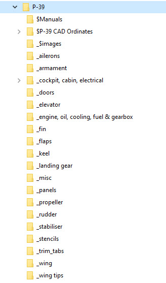
Let’s take an example from the Bell P-39 Airacobra.


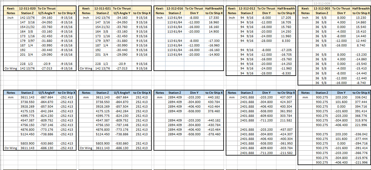
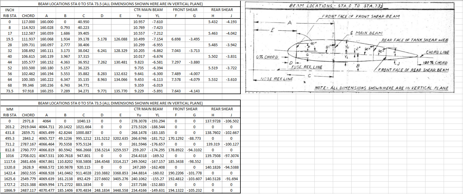
For this aircraft, the ordinate dimensions are noted on the actual part blueprints so I have developed a series of tables listing this information in excel spreadsheets as shown. They list the Station Location from the aircraft Zero plane (this is usually identified by the manufacturer). The Station number is actually the station dimensions from this plane which defines the Z component. The next column on the table is the Vertical Y-component or the dimension to the Waterline and finally, we have the Horizontal X-Dim which lists either the Buttock Line position or Half Breadth dimension.
Commonly the Horizontal axis on the aircraft is known as the Fuselage Reference Line (FRL) or occasionally the Thrust Line. The Vertical Line is simply known as the Centre of the Ship to the Aircraft.
Waterline (WL): Horizontal Axis, Buttock Line (BL): Vertical Axis. An example of this is where we commonly have a designation like WL4…which means the Waterline at 4″ above or below the Centre of the Fuselage. So when it is not specifically dimensioned you would know from the designation where it is located.
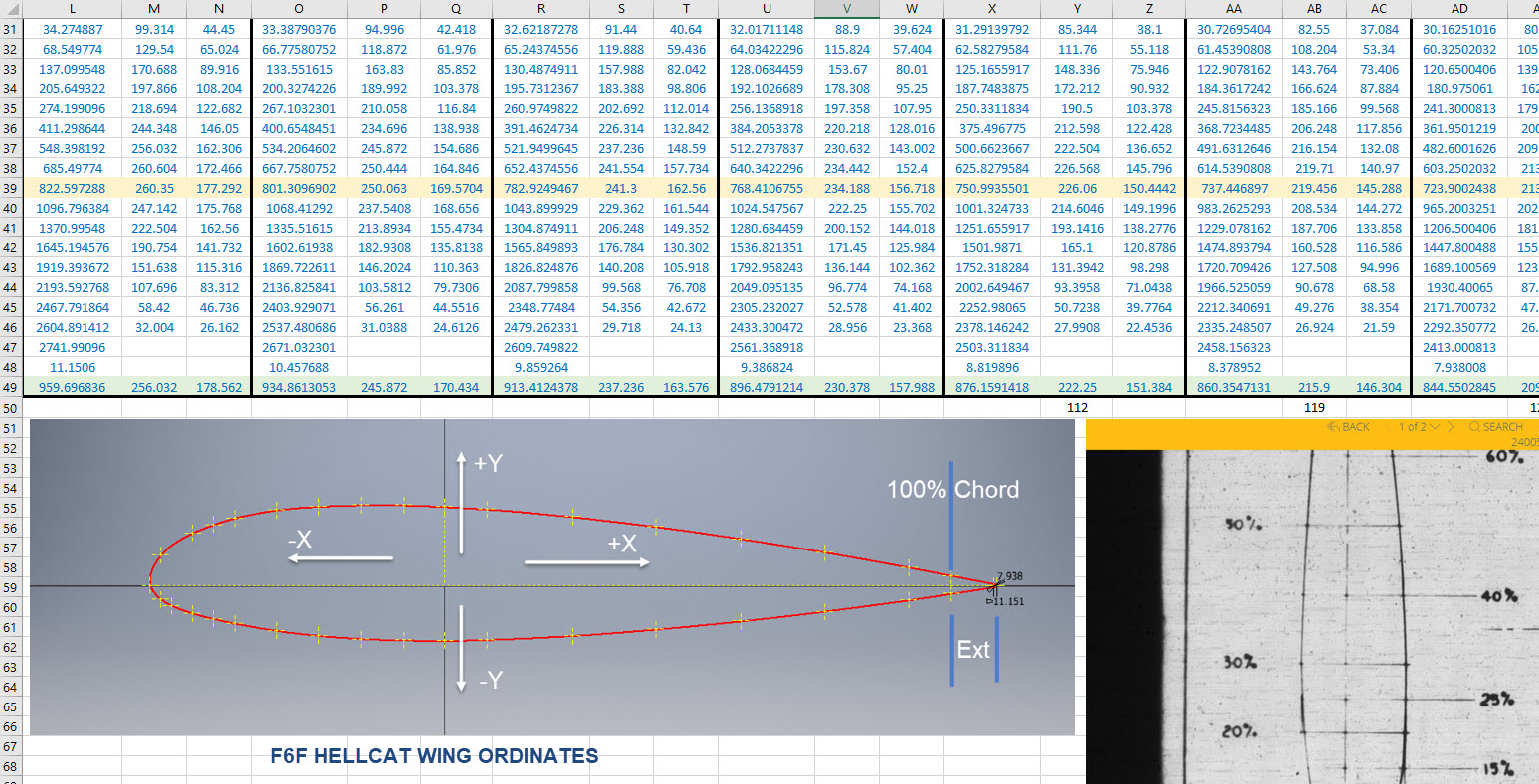
Once I have the tables of known dimensions I would occasionally extrapolate this data to list the actual X,Y,Z dimensions in separate tables to make it easier to copy and paste into any CAD system.

As you can see from the above image, the dimensions are initially listed in 3 columns, X,Y,Z and next to that is the same data listed with comma delimiters. The reason for this is because Mechanical design packages like Inventor and Solidworks will recognise separate columns of data in the requisite order as stated whereas Autocad will require combined data for Mulitple Point input as comma-delimited.
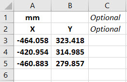
The way I do this is to have a separate excel spreadsheet which I keep on my desktop which I call Scrap.xlsx. The format is common as shown in the image on the left though I should note the top 2 rows are optional. If there are no units specified it will default to the CAD template units. I usually don’t bother with the top 2 lines. Once the points are imported into CAD I tend to delete the values in the spreadsheet Scrap.Xlsx and start again.
The comma-delimited column data in the above image can also be copied onto a Notepad Text file and used in Autocad. Worth noting is that if you try to import X, Y, Z coordinates onto a 2D sketch it will only import the first 2 lines and ignore the third…so make sure the columns are in X, Y, and Z-order.

An important consideration is that not everyone uses Inventor or Solidworks or even Autocad which is why the spreadsheets are critical because then everyone can use the data to build their own models.
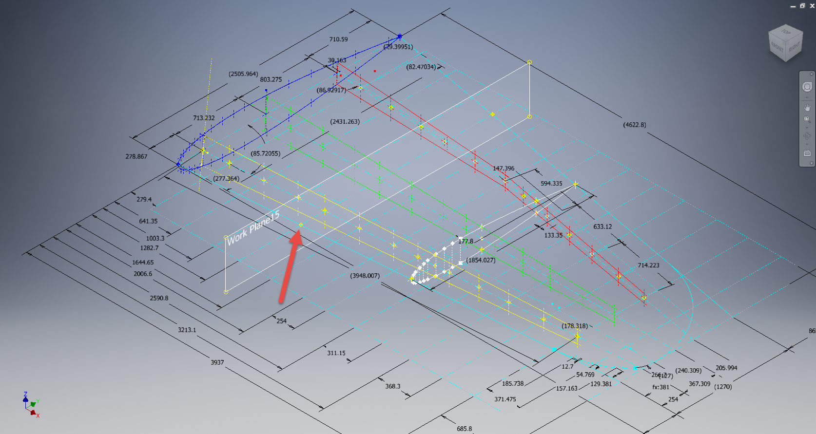
Actually building the model can be done in several ways. You can build a part file with multiple workplanes on which to sketch the profiles from the input ordinate data or individually in separate part files. You can model the parts in context, i.e. taking into consideration the Station (Z-axis) dimensions so when input into the assembly they locate correctly in 3d space. Or just the X, Y, ordinates in the part file and locate to the Z-axis offset in the assembly.
Dealing with problem data:
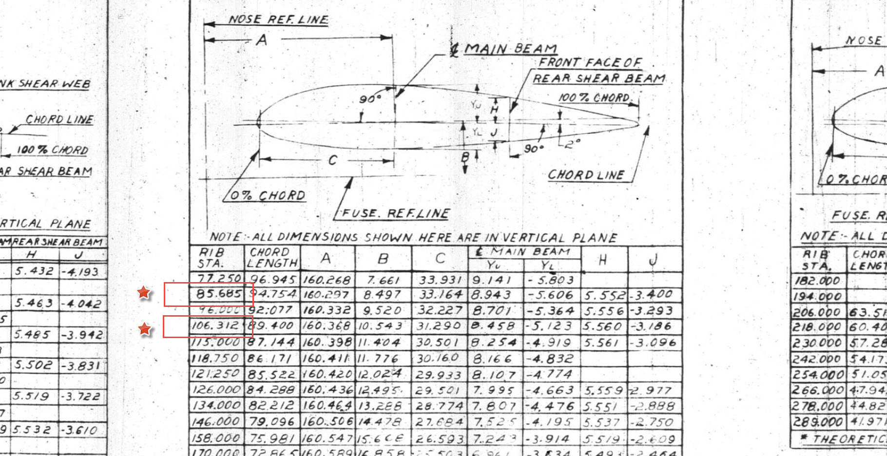
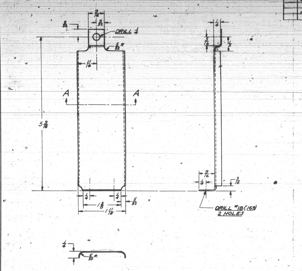
This is perhaps one of the main driving initiatives behind the development of Ordinate datasets with regards to the legibility of the original manufacturer’s blueprints.

This example is actually quite reasonable whilst others are quite illegible. As most of these datasets are listed in Inches; which are normally factions; it is easy to confuse whether a fraction is 3/16, 5/16 or 9/16 when all you have is a blob of dark matter.
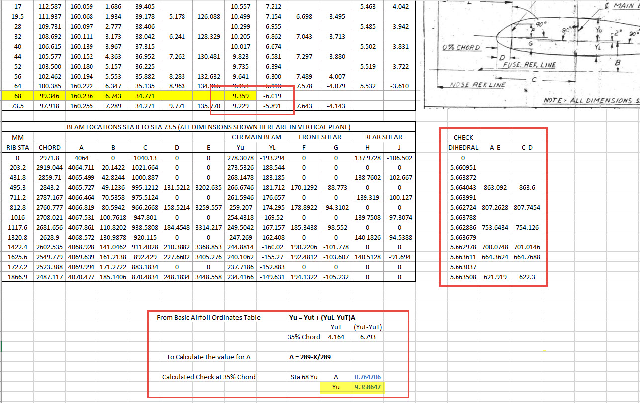
What I tend to do in these circumstances is develop what I do know and develop the profile using splines to connect the points and then apply the curvature to help determine the missing point location or check that a point is correct.
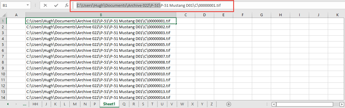
Occasionally points you need to complete a profile just don’t exist on the blueprints or are completely illegible which will then require more extensive research. Sometimes this information is included in the maintenance or Repair manuals or in the case of the P-51 Mustang a missing point was actually found in correspondence. Either way compiling this data and building the profiles is very time-consuming.
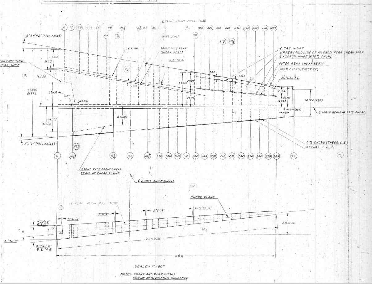
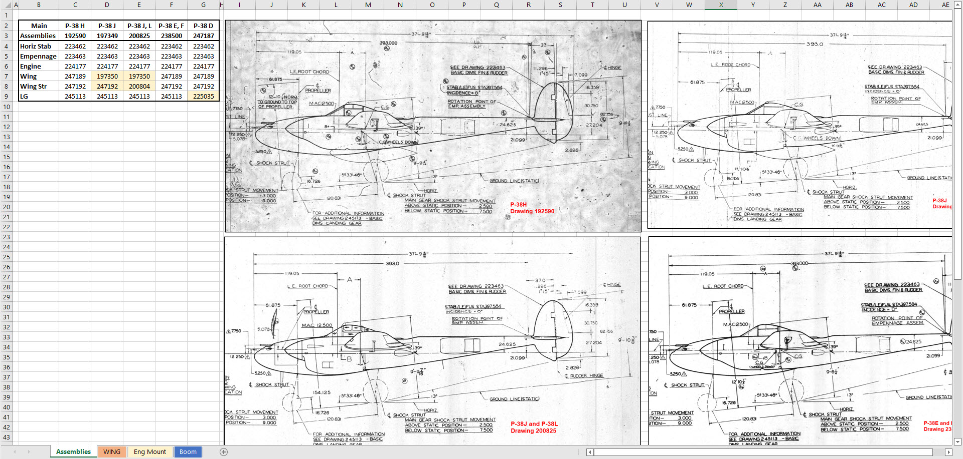
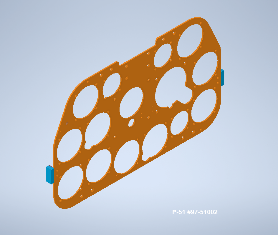
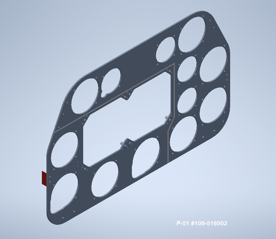
Another fairly common problem is wrong dimensions. Every aircraft project I have worked on from this era has this problem, not because they are bad draughtsman (very much to the contrary) it is because many of the drawings are only records of the Template Lofts and occasionally the dimension is recorded incorrectly. The skill is identifying that the dimension is wrong; it is unwise to assume that because something does not look quite right that it is actually a mistake. So you have to check with associated parts and layouts to be sure.

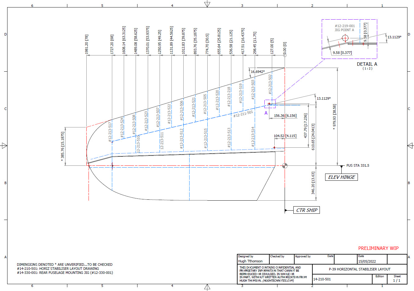
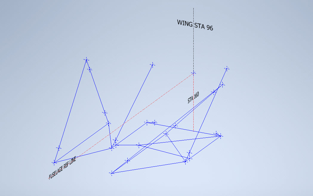
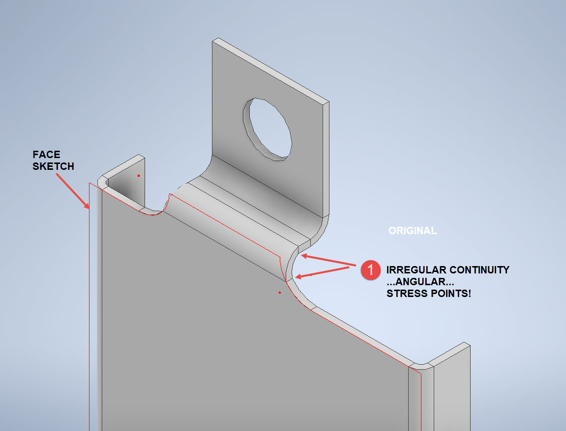
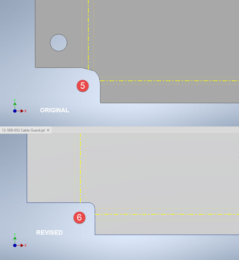
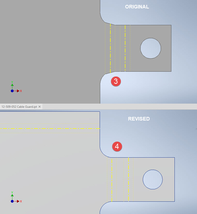
The image above is the Horizontal Stabiliser leading edge. The rib in blue (1) was obviously wrong because of a distinct kink in the curved edge, which when corrected aligns well with its neighbours. The one in red (2) also appears to be wrong even though the curvature looks fine the forward edge does not match with the projected alignment (I tend to use an Axis feature to check this). Before I apply any corrections I will check the part drawing and then the assemblies to determine if there is an error or if it is actually a design feature.
Locating Sketch Datum Points:
Creating workplanes for sketches as offsets from the primary X, Y or Z planes tends to copy the originating plane datum point which is not always where we need it to be when importing a series of points. The best option is to use the Parallel To Plane Through Point when creating a workplane as this allows you to select the point which will be the datum point on that sketch plane for locating the point data.
I previously wrote an article on this here: https://hughtechnotes.wordpress.com/2017/07/27/technote-inventor-sketch-datum/
Some of the datasets are setout specifically to make it easier to input the data from the spreadsheet. For example, the extrapolated X, Y, and Z, coordinates for the P-51 Mustang wing have been compiled and calculated so they will input at the location of the 25% wing chord. This is assumed to be the logical setout point from the CAD World Coordinate system which saves you a lot of hassle.


If however, you have to create a workplane on an incline this option may not be available in which case you need to adapt the local sketch coordinate system to suit the required datum point.
In Inventor, you would right-click the Sketch in the model browser and select the Edit Coordinate System option which initiates an adjustable Coordinate icon on the sketch.
Suffice to say this icon can be manipulated, moved and rotated to any point on the sketch to suit your requirements. I will do a more comprehensive article on this shortly.
Other Excel Ordinate Examples:

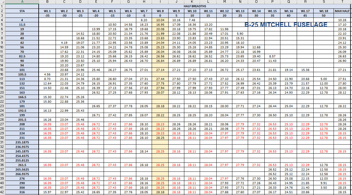
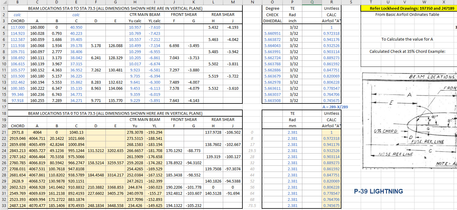
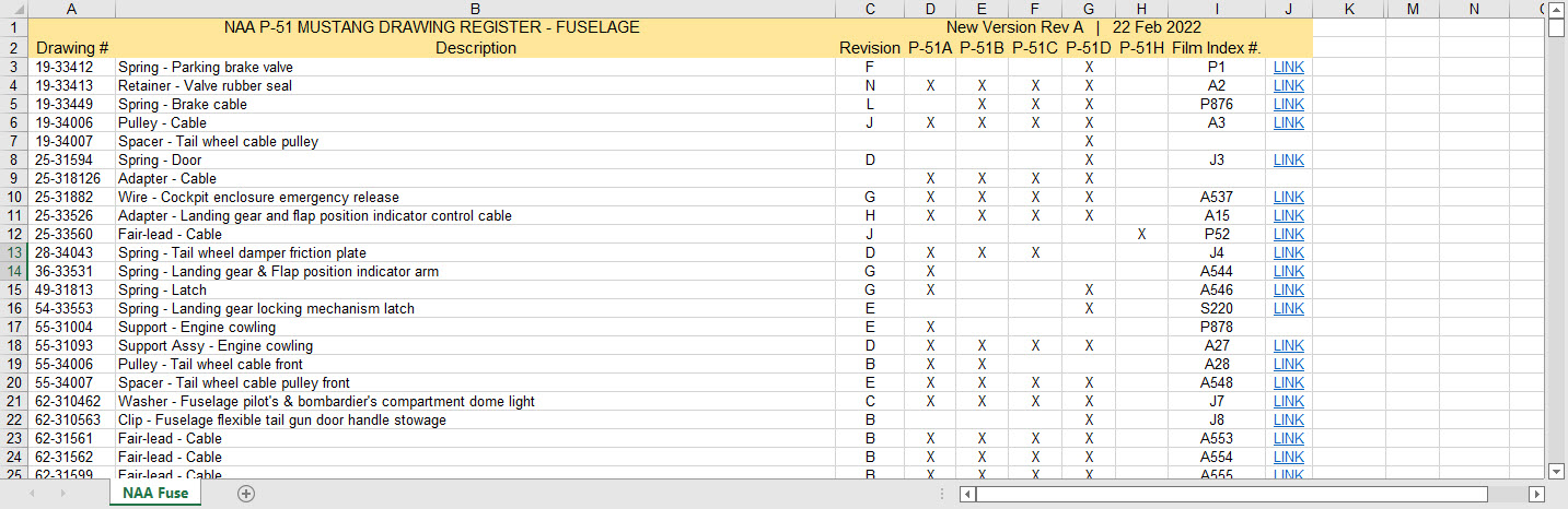
The actual layout of the Ordinate spreadsheets depends entirely on the form from which the data is developed. Where the original blueprint data are listed in tables I will generate the excel spreadsheet in exactly the same format…which helps when checking the data input. If there are no tables but data from the part drawings then I will generate tables according to how the dimensions are noted.
All the dimensions are listed in Inches and Millimetres. I normally extrapolate the X, Y, and Z coordinates to millimetres as this is easier for me to work with…but it is easy to change that to inches if required. All the spreadsheets are fully editable and not restricted in any way.

Finally a quick Excel tip:
If you work with percentages a lot you will find this useful. When entering the value in the cell just add the % sign after the numbers and Excel will automatically format the cell as a percentage value.
Ordinate Data set Availability.
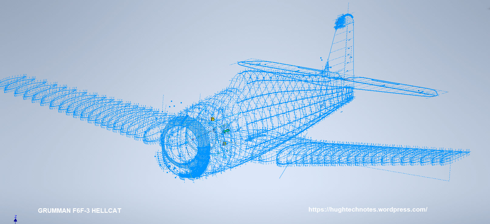
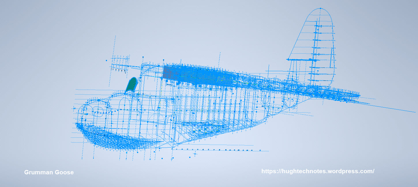
The NAA P-51 Mustang (probably the most comprehensive study) is available as a separate package from the Blueprints archive. The B-25 Mitchell is also a separate package and the Grumman Goose. The F6F and F4F are currently included in the Blueprint archive as they are not so well organised (work in progress) for now.
The Bell P-39 Airacobra is currently included with the blueprints but as I am now working on a new update this will shortly only be available as a separate package.
The P-38 Lightning is brand new and will not be available until June.
Final Note: All the Ordinate packages include the 3D cad model as developed in Inventor. This should not be an obstacle to anyone wanting to interrogate the model as a 30-day evaluation of the Autodesk Inventor is readily available for download. You can even extract sketches from the model as DWG files if required.
Many of the Ordinate packages include fully dimensioned Autocad 2D drawings and PDFs. These are mainly layout drawings and critical location information where it is essential to better understand relationships between wings, fuselage and empennage. Again all these are fully editable.
For all inquiries and feedback please get in touch: hughtechnotes@gmail.com