P-39 Airacobra Restoration Update:
The FM2 project has been parked for a while as we must focus on the P-39 Airacobra Restoration project. The work has shifted to the Cockpit where we will literally be building a new cockpit from scratch. This is a lot more work than we initially envisaged, but ensuring we get this right is necessary.
Let me take you through some of the work involved in this process and what I did to circumvent areas where little or no information was available.


So far we have the Trim Tab Control, the Switch Box and the Centre Radio Console. The Switch Box and the Trim Tab Control have already been fabricated and test-fitted. It is very important to check the fabrication before the final installation as there is likely to be some variation in the actual versus the perceived location of structural elements. Normally I also provide additional templates to help with this process.
The Radio Console is one area where I had to do a lot of research and development work due to the lack of specific Bell drawings for the main panel. Trying to layout a panel correctly can be quite difficult when the panel drawing is not available so you have to innovate solutions from known information for the P-39C, C, D and F variants. I forgot to mention this restoration project is for the P-39N.

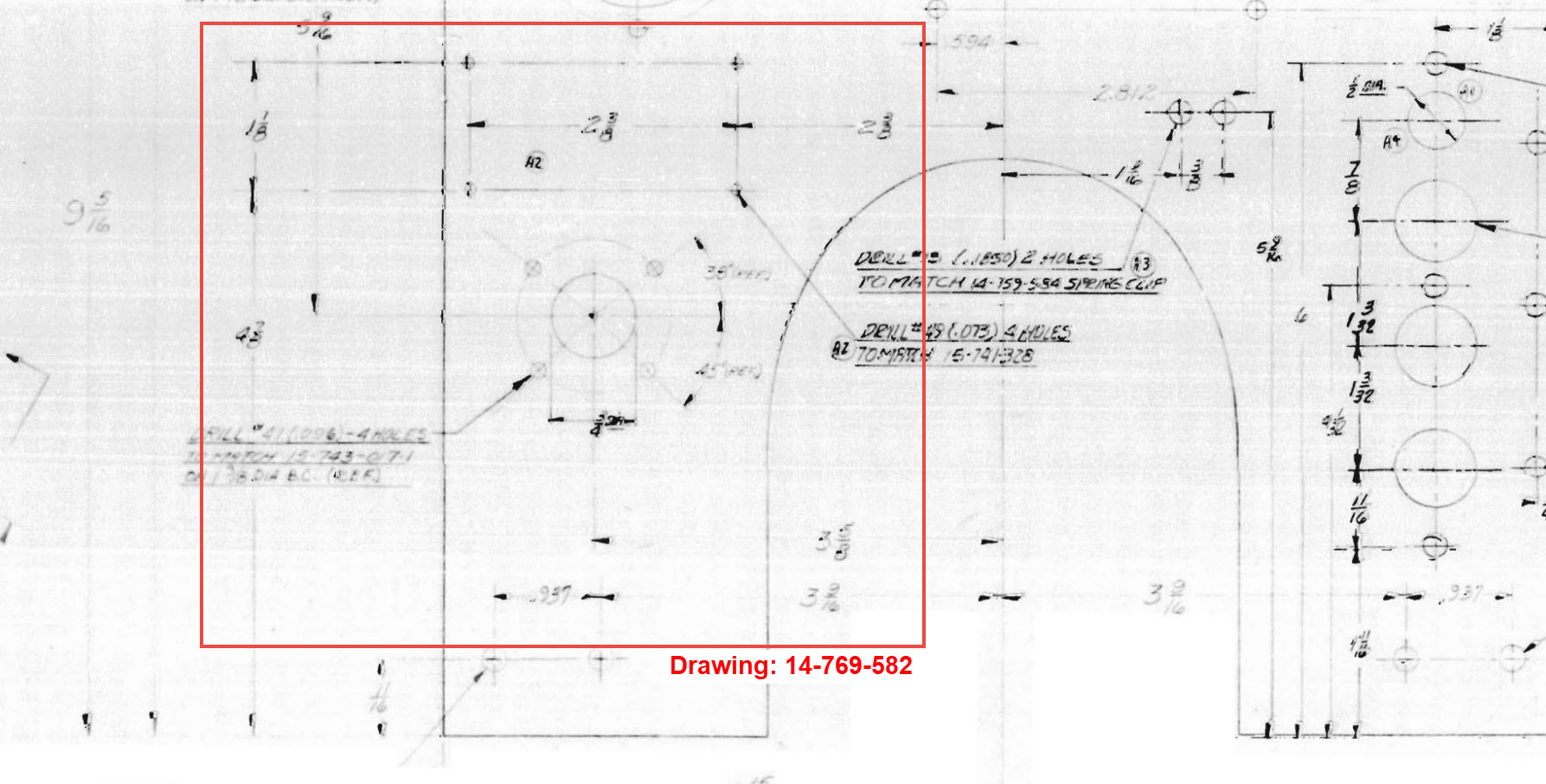

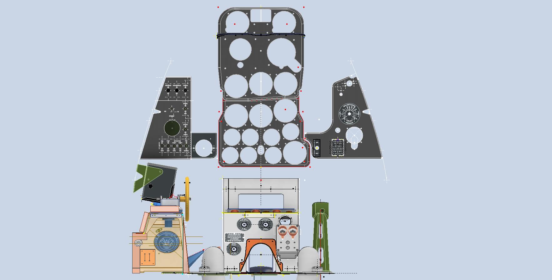
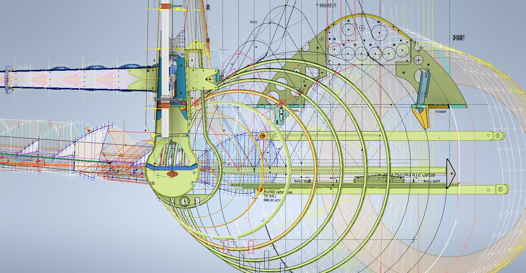
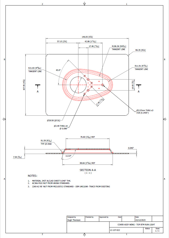
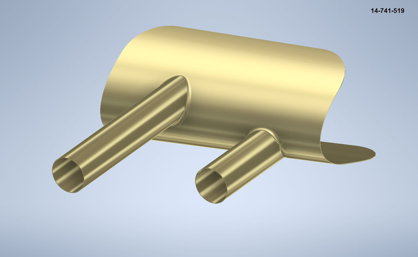
The process involves reviewing all existing resources including blueprints and manuals for all the other variants and extrapolating useful information to establish a viable layout for our P-39N. The first image above is a partial view from Drawing 12-769-011 (P-39C, D, F) which shows the location of the Radio Switch box, the same as required for the P-39N. The Switch box itself is a supplier component for which we don’t have the specific dimensions however, we do have the Name Plate which was used to determine the actual box dimensions. The second image is the location of the Bomb Release from Drawing 14-769-582 (P-39D-2) similar to the requirements for our P-39N. The third image is the 37mm Gun Charger and Loader.
Often when there are updates and changes to instrumentation panels it is common to reuse existing references where possible to simplify change. In the case of the Gun Loader Charger, the centre-to-centre distance of these controls is paramount as defined in Drawing 15-769-017 (P-39D) and replicated in later versions. Collectively we now have pertinent information that in combination will give us the information needed to lay out that actual panel for the P-39N. Still, some finishing work to do on this and I am satisfied this is a good solution.
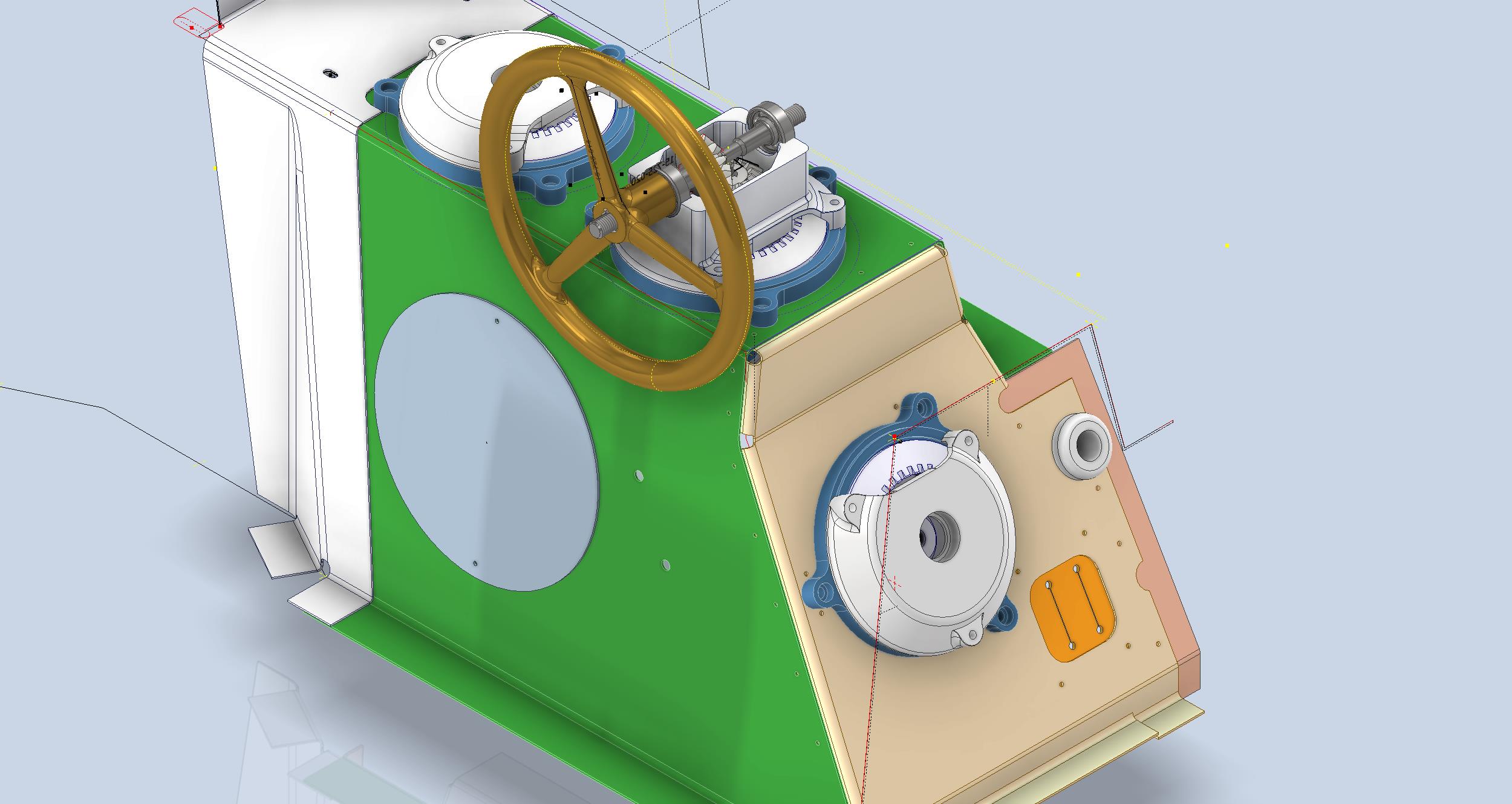
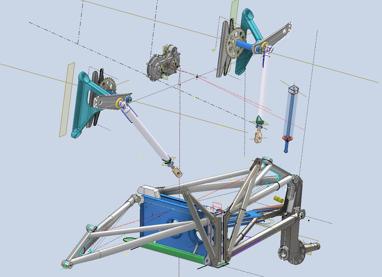
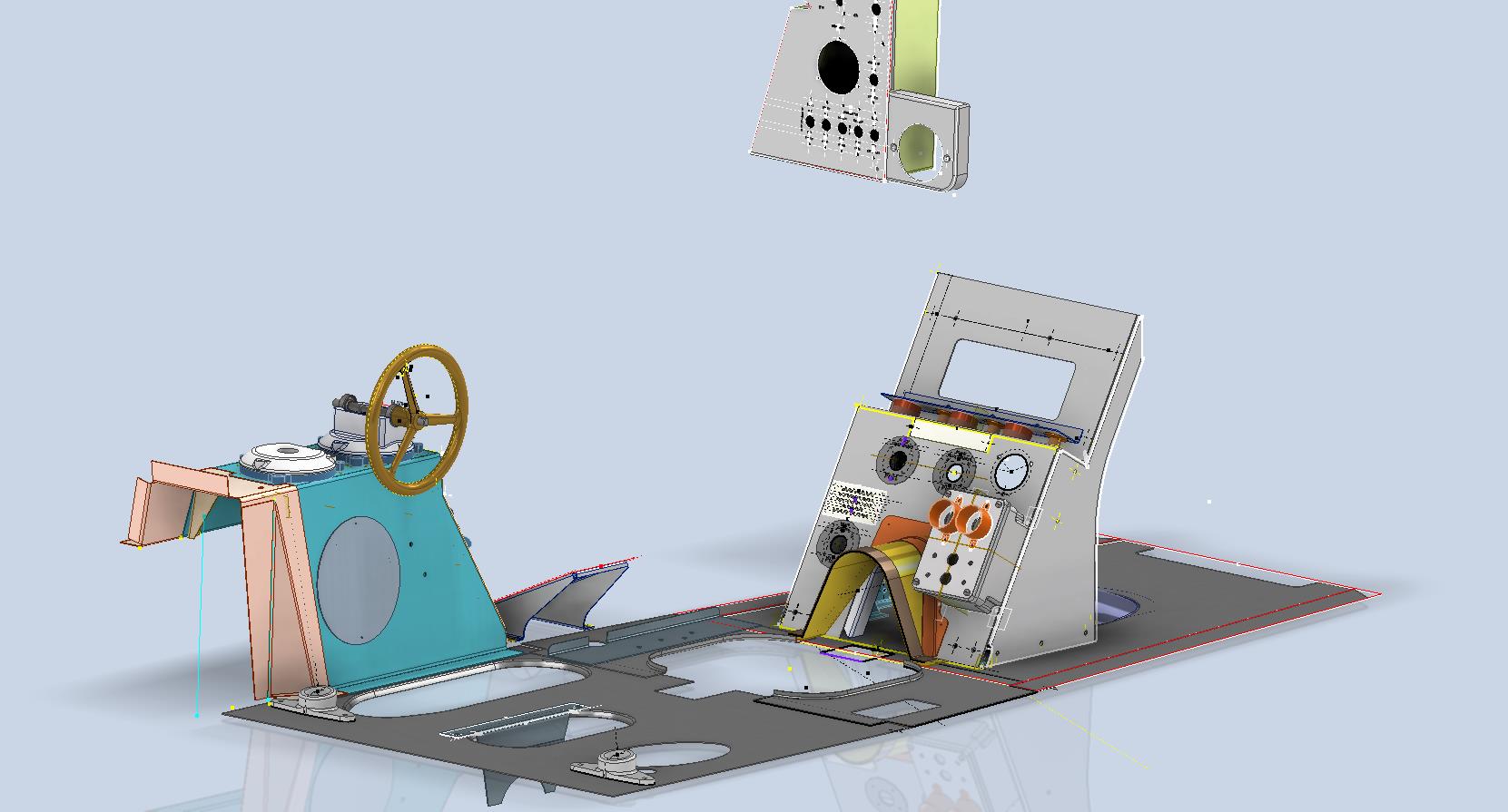
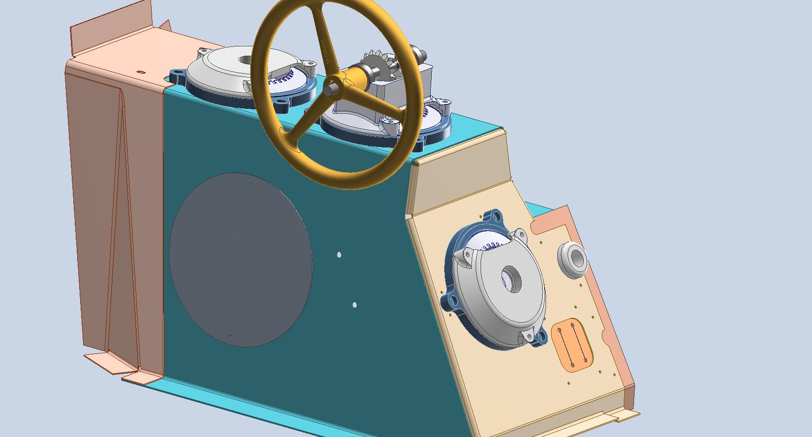
You will notice that I have modelled in the floor plates which was necessary to help check instrument locations. Sometimes you may have to actually model the cable routings, floor penetrations and the power conduits to check termination locations which in turn checks instrument positions. Fortunately for this restoration, the majority of the floor plates are reusable except for the Aft plate which will need to be replaced…a temporary plate is currently installed for safety reasons.
Often with a little bit of research most problems where drawings are not available or in some cases illegible can be overcome and it helps to have some background knowledge of how the design process actually works and how key information is retained throughout the development of new variants.
In most cases, research is the key to achieving solutions; take time to review existing materials and not just drawings but also manuals and occasionally correspondence to find relative data that will assist with your goals. Often engineers will trace outlines and profiles from scanned blueprints which in my opinion is not good practice when a little research and time will achieve more accurate and professional results.
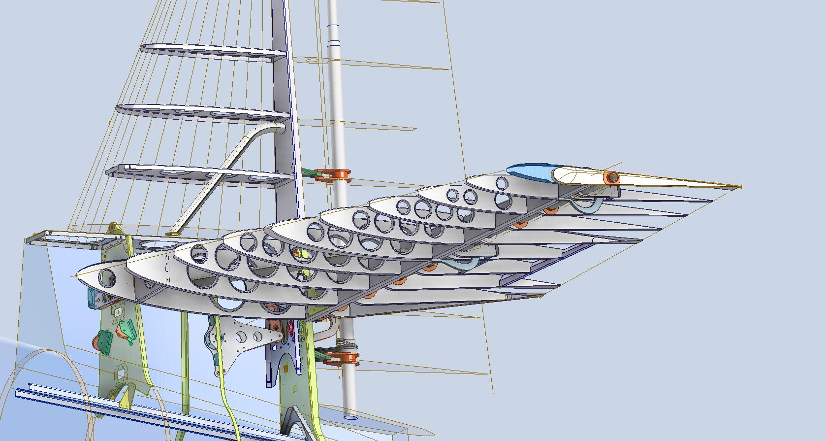
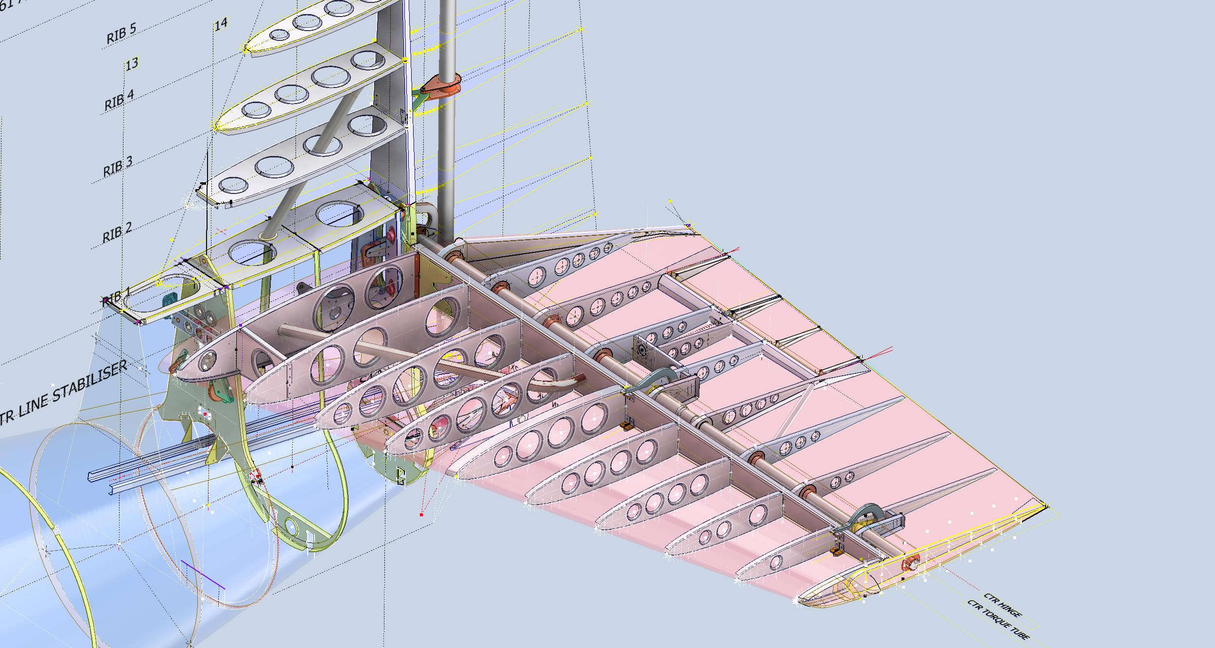
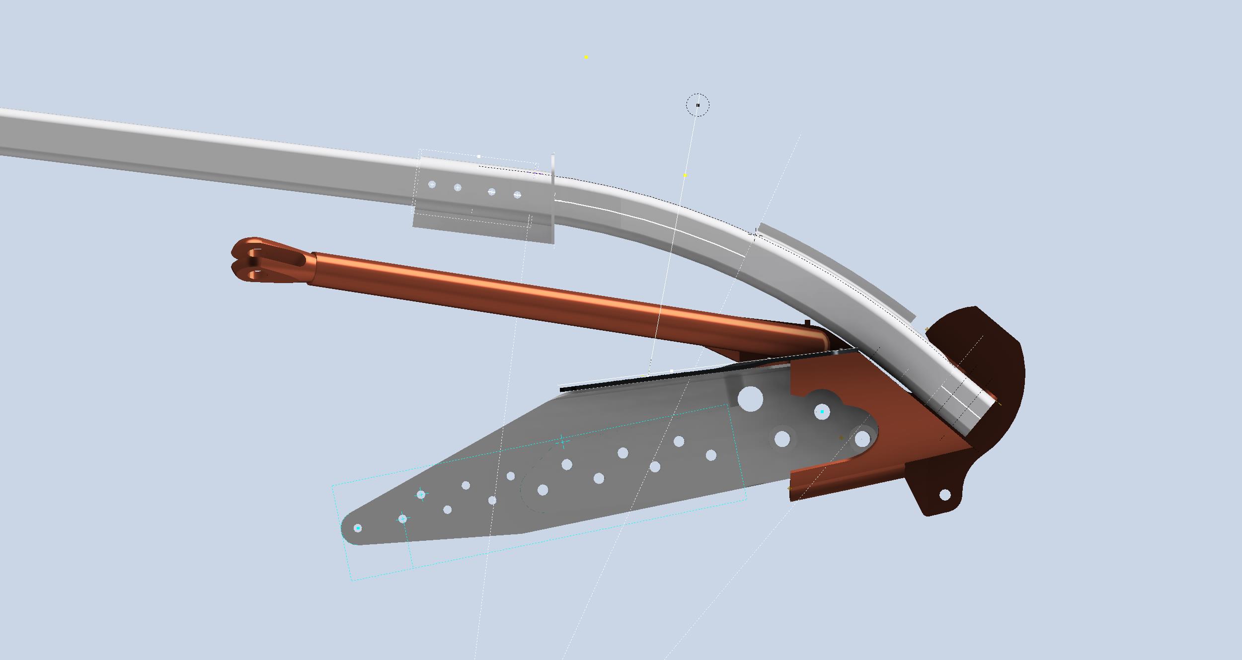
Update 10th May 2024:
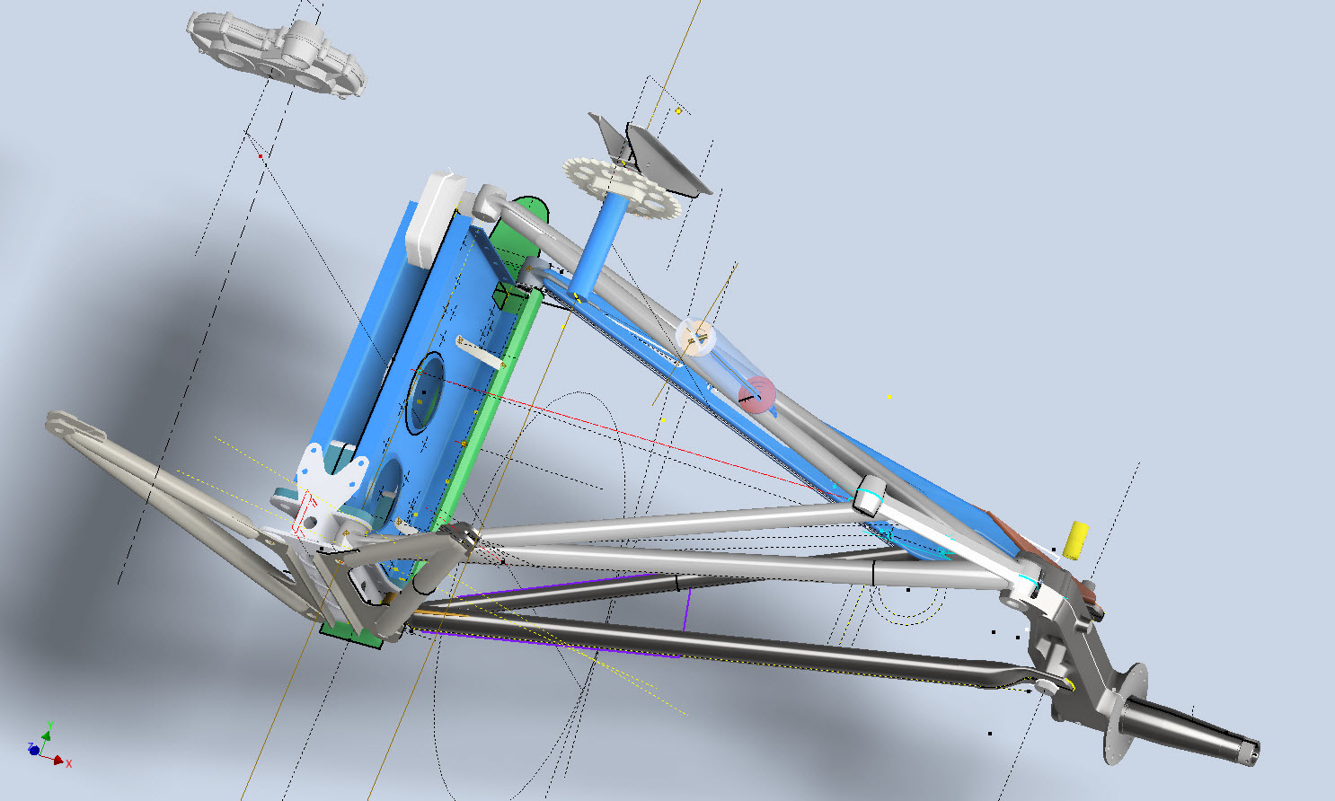
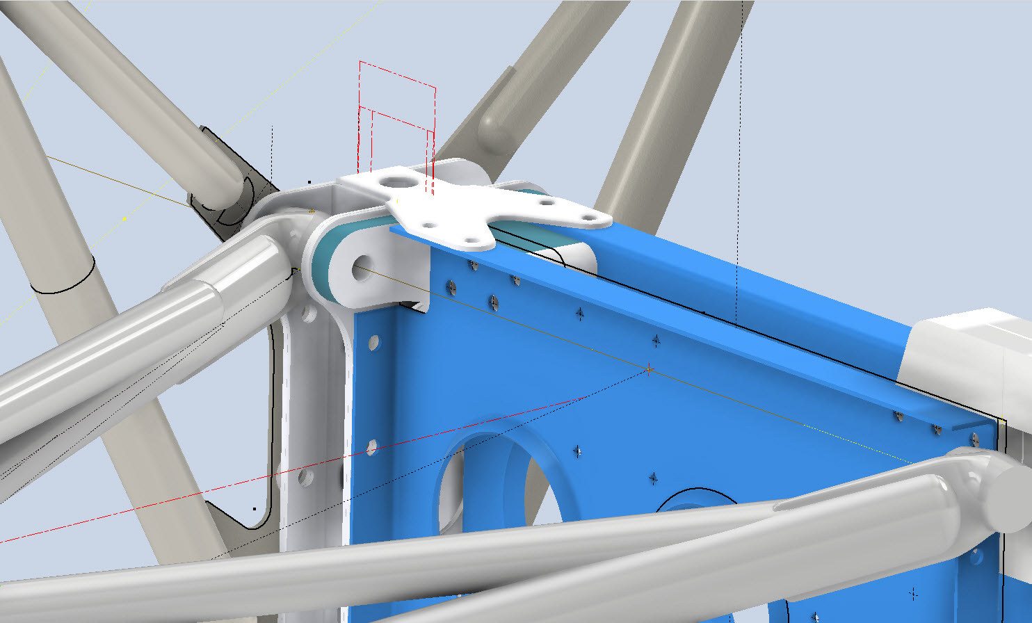
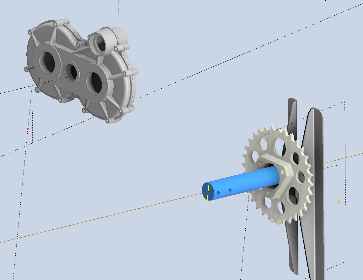
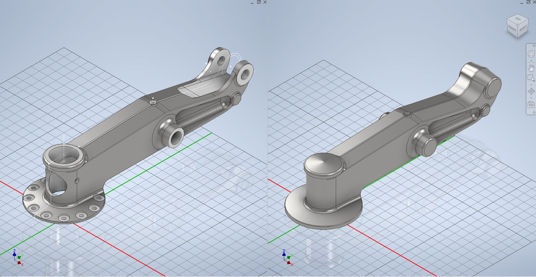
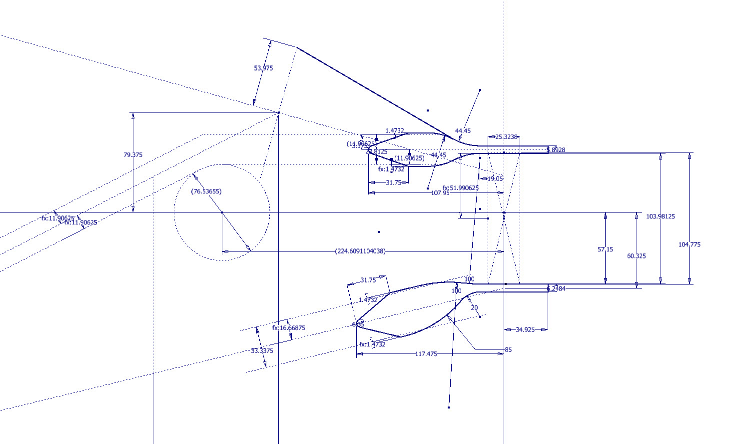
A few images that show the latest update for the P-39N Cabin model.