HiRise data and WRL Conversion.

HiRise data and WRL Conversion:

It has been a while since I last posted an article due to being busy with other projects. During some research activites, I came across a number of subjects that may be of interest, two of which I would like to share.

The first one is the HiRISE Digital Terrain data models on the University of Arizona website. The website contains datasets that are digital extractions of surface terrain scans of the planet Mars. The DTM datasets are publicly available for research and modeling of geological processes.

PSP_007100_1520

Naturally curious I decided to investigate the possibilities of modeling and rendering of these datasets from which I produced a few preliminary 3d terrain models using Blender and rendered in Keyshot…Gorgonum Chaos:

mars10The technique I used is described in this video on Youtube, clearly explaining the process. To me, this is incredible stuff and thanks to the University of Arizona for all their dedicated work in developing these datasets. So have a look and check it out for yourselves.

The next subject is WRL. WRL is a file extension for a Virtual Reality Modeling Language (VRML) file format often used by browser plug-ins to display virtual reality environments. VRML files are known as “worlds,” which is what WRL stands for.

One of my many interests is Tensegrity, a structural form of tension and compression members first developed by a chap called Kenneth Snelson. The internet is full of examples of this structure concept inspiring many variations from fairly simple to very complex designs. I have developed a few of my own.

delta

Many of the practitioners in this field make datasets available for personal use and one particular format they use is the VRML (WRL) so you can view the design in 3d.

For the simple structures similar to this image the design and construction are not that difficult, however when it comes to developing your own version of the more complex examples it can be a real headache. Although some datasets include actual point cloud data the process of matching pairs of points to reconstruct the design can be a nightmare.

The obvious solution would be to convert the WRL model into something usable that could be used as a guide for developing a 3d cad model. I tend to favor Meshlab for doing this as it is one of the few programs that will accurately convert the imported data.

meshlab

The WRL model is converted into a series of mesh objects that we can export as an OBJ or STL file and then import into Inventor.

Once in Inventor, it is simply a case of selecting each of the compression struts and “Fit Mesh Face”. Select the “Auto Fit” option for each member and it will create a surface from each mesh representing the struts.

The tension wires are then created as a 3d sketch using the background mesh model as a guide. At this stage, the model is a workable composite but may require micro adjustment for the tension wires to ensure the finished item is properly constrained. I would reverse engineer this model and reconstruct as an assembly and apply the microdimensional adjustment to the groups of tension wires to ensure the absolute accuracy of the final design.

It is beyond the scope of this article to go into the detail of every step, but if you require information on any of the topics please feel free to drop me a line.

Tensegrity Conv

I hope you find this article interesting and have fun.

Restoration Project: Corsair F4U-1

Restoration Project: Corsair F4U-1

This is great news; a good friend of mine has just acquired the wreckage remains of a Corsair F4u-1.

IMAG1368

The long-term plan is to restore this Corsair to its original specification as a standing exhibit. It would be wonderful to restore to flying condition but the projected cost as it stands is quite overwhelming and to achieve flight status would probably double that.


IMG_4038.JPG

P1060200.JPG

We will be setting up a dedicated blog and website to record progress on this restoration. Part one of the project is to develop a master lines plan which will be used to design the jigs required to rebuild the fuselage and wings.

Any contributions to the project, regardless of how small will be greatly appreciated.

Technote: Inventor LT BOM!

Technote: Inventor LT Bill of Material.

I normally use Inventor Professional but recently I decided to have a look at a common issue with Autodesk Inventor LT which is a part only product. Essentially the “lite” version of Inventor with limited functionality that excludes sheet metal, vba, ilogic, assembly mode and Bill of Material!. Technically the BOM capability is not a function of Inventor LT which I suspect is due to the fact it has no assembly environment but there is a workaround.

I should note that Inventor LT is a very capable modeling product which is ideal if you are mainly developing parts and if you do require an assembly environment to check the alignment of mating parts then you can use the derived function as explored in a previous post to assess this.

Whilst the product may be limited it does have a lot of functionality that can be exploited to overcome some of the limitations and the BOM is just one example of a situation that the forums, in general, described as something that cannot be done!

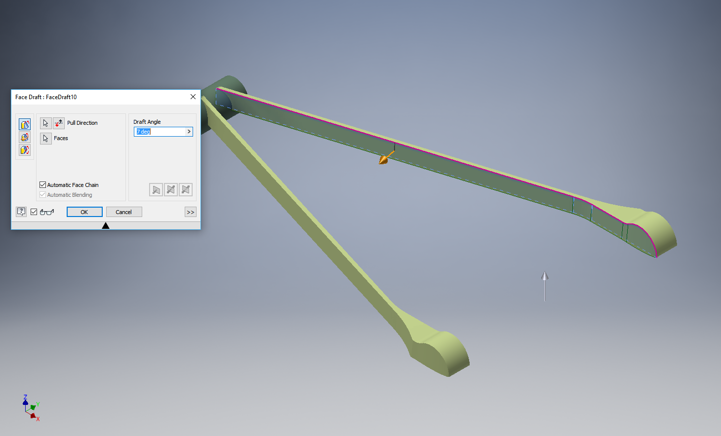
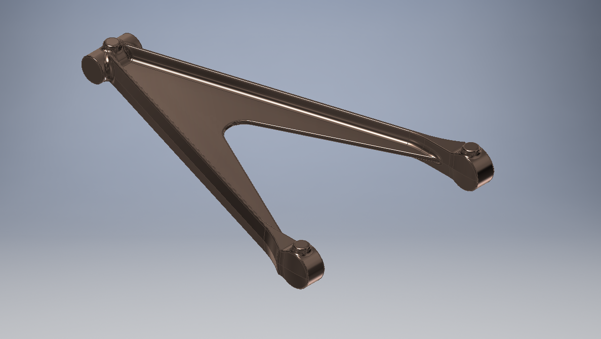
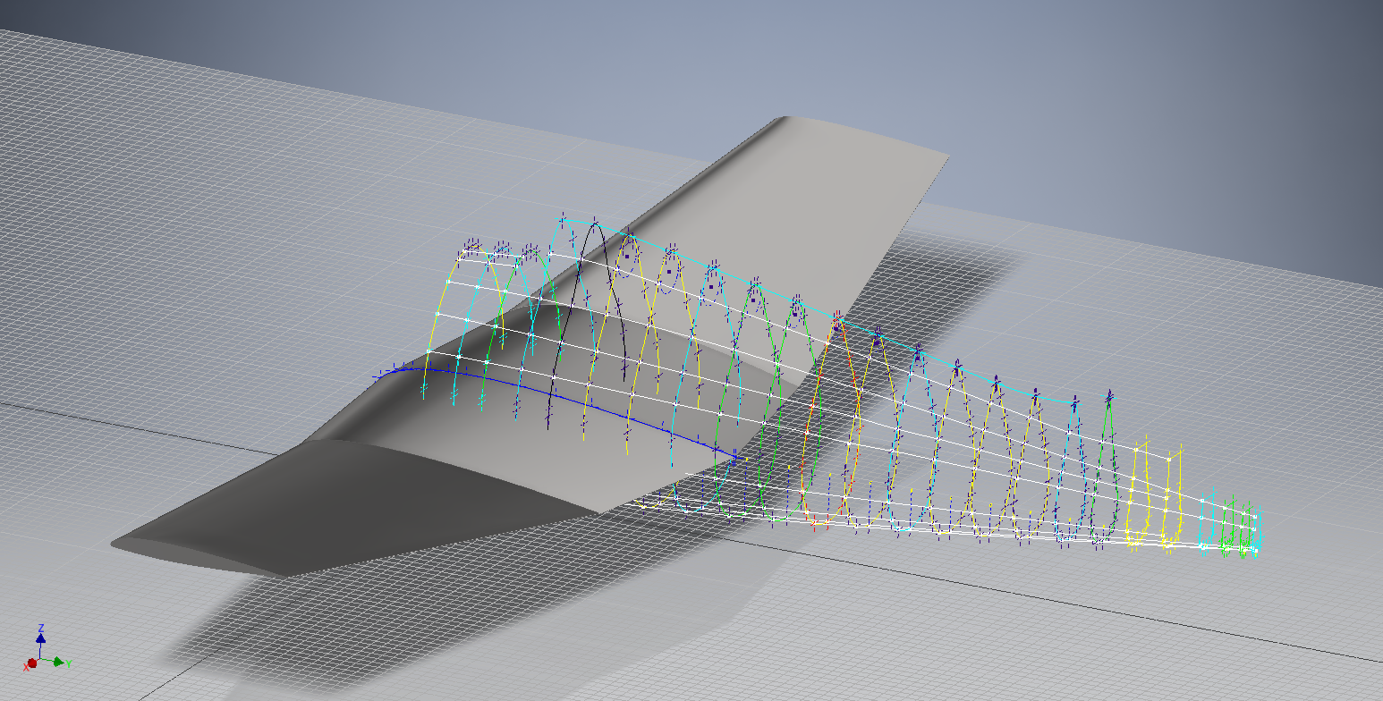
For this example we will continue with one of the parts from the previous article: the Bell P-39 Airacobra Centre Bulkhead fixing bracket.

2017-07-31_14-31-28

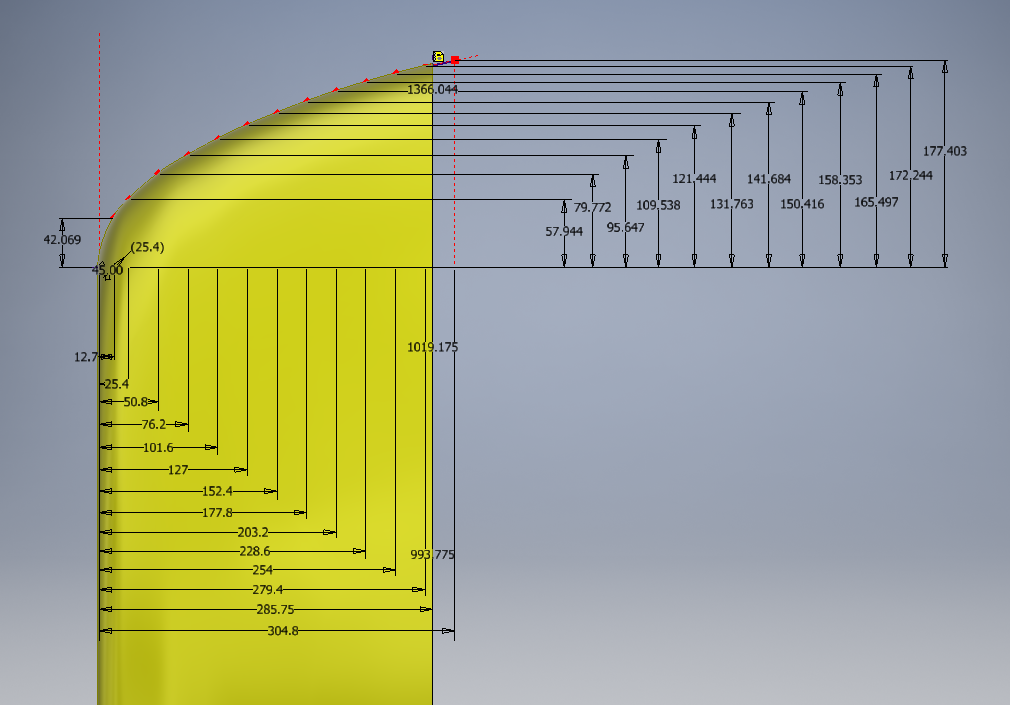
What I wish to do is have this part fully dimensioned on a drawing that also contains a basic table of properties that may be useful to the chap responsible for buying the raw material. Okay, I accept that the following image is not fully dimensioned but my primary interest is the generation of the BOM.

2017-07-31_15-32-56

Inventor LT like its bigger brother contains a lot of part data which is accessible via the iProperties and Parameters, which we will utilize by using the iPart feature.

Normally iParts are used where a single part may come in varying sizes or configurations that share the same basic features; for example bolts! In this case we are creating only one version of the part. By adopting the capabilities of iParts we will create a table of selected data within the part file that we will later use as a data source for our BOM.

2017-07-31_15-59-16

I won’t go into the technicalities of creating an iPart, there are many online resources that go into this in detail. Generally speaking, when creating an iPart you have access to all available data including parameters, model hierarchy data, and iProperties as shown above and it is simply a case of selecting the data you want.

2017-07-31_15-52-34
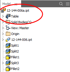
This creates a Table which appears in the model browser. It is usually a good idea to give parameters meaningful names as I have done here for the Length, Width and Height.

The Description values are from the iProperties whereas the Length value is from the parameters.

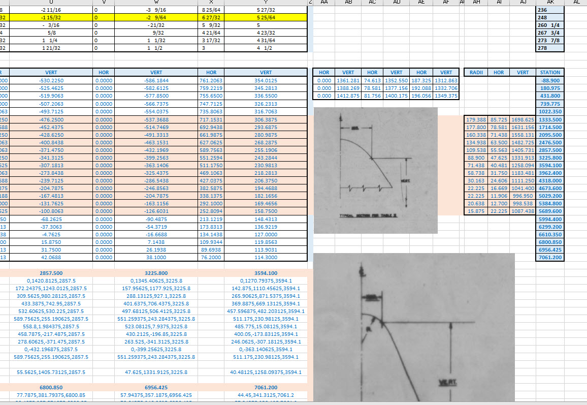
This table can be further edited within Inventor LT or externally as an excel spreadsheet.

In the drawing environment, you select the General table option, Select View and then Column Chooser, add required columns, select OK and insert the table into your drawing.

2017-07-31_16-04-53

…and there we have it…a BOM in an Inventor LT part drawing.

Part Quantities:

I have not mentioned part quantities which of course would be a prerequisite for any purchasing decision. You can, of course, create a parameter in the model file for quantity and include that in the table, but if this part serves a number of different assemblies then the quantity will vary accordingly.

Given a typical scenario where you are the manufacturer of components working collaboratively with other companies on a project how do you track quantities when you are using LT and the other guys are using Inventor and building assemblies.? You could, of course, just phone them or email them but as production schedules are critical you need a way of immediate notification of quantity changes.

I faced a similar dilemma when I developed a modular solution for a power distribution company for design of sub stations. This resulted in vastly reducing the design time by over 60% which meant the procurement chaps had to up their game to keep on top of things.

Modular Approach to Sub-Station Design

The solution gave access to all project material BOMs without needing to bother engineers to create structured BOM extractions.

Briefly what we had was a top level assembly BOM which was interrogated by a custom database application to read the Part Name column and then search a folder of extracted cad model BOMs with the matching name and multiplying the quantity column in the part BOM with that of the assembly.

2017-07-31_17-22-30

For example, the database would open the top level database above, read the columns Name & Descr (to be sure we were only looking for modules) and then import the corresponding data files with those names into the database. In this case, we only have 1 quantity per part, but that could be anything and the associated part file would be multiplied accordingly.

This is a very basic overview of what was done and beyond the scope of this blog to describe in detail. We have already demonstrated how to create and extract tables in LT and the main point here is though you may only have Inventor LT there are many options for creating data-sets in tables that can be shared and used productively in a collaborative environment.

Incidentally, the database I created was another of those instances where something could not be done!

Technote: Inventor Sketch Datum

Technote: Inventor Sketch Datum Point.

This is one of those instances where you do something on a regular basis and don’t really appreciate the significance of the process. What I am referring to is when you create a sketch Plane using the option “Parallel to Plane Through Point”.

2017-07-27_00-33-25

It transpires that this selected point becomes the datum for the particular sketch created on this plane. For this example, for a P-39 wing rib, we have selected a point for the Plane location along the wing leading edge as shown.

P39 wing1

The Bell P-39 and similarly for the P-51 Mustang the wing ordinates are set out from the leading edge of the wing so it makes sense that the rib sketch is setup with a suitable datum point. You can tell the location of the temporary datum in the sketch applied to this plane by the position of the main axis.

This is the really interesting part, when you now import a set of points from the Ordinate spreadsheets it will recognize this sketch datum and import the points relative to this point irrespective of the model origin.

2017-07-27_00-35-12

2017-07-27_00-39-42

This is very useful particularly for these aircraft projects as we tend to use a lot of ordinate data for the outline geometry.

Another Quick Tip:

To automatically apply a tangent constraint to a sketch line just select and drag the line from an existing line and the tangent constraint will be applied.

2017-07-27_01-14-56

Technote: P-39 Inventor Facedraft

Technote: Bell P-39, Inventor FaceDraft

Draft angles is actually a common requirement when working with aircraft components, particularly forgings, and it is surprising that I haven’t written an article on this before now.

Facedraft in Inventor is a feature that allows adjusting the face or faces of an object to a specified angle. A more detailed overview is described in this Autodesk article Face Draft feature

Occasionally the implementation is not quite so straightforward as noted therein and some outside the box thinking is necessary. Thus was the case when I was building the forging component for the P-39 Landing Gear Nosewheel Scissor.

To build this component I created 2 separate solid bodies, one for the cylinder item and one for the fork. The fork is split about the X,Y plane with only the outline of the top half being modeled to facilitate the initial face draft.

2017-07-23_00-00-14

For the first option, I selected the X,Y plane and then for the Faces I selected the automatic face chain option and placed the cursor close to the top edge as shown. If you required the face angle to originate from the bottom edge then you would select the faces close to this edge.

I then trimmed out the inside profile of the fork and applied a face draft as above.

2017-07-23_00-08-00

Now it was only a matter of mirroring the fork solid to complete this portion. Notice the solids are still separate items which will be combined as one after inclusion of the central web component.

2017-07-23_00-12-51

There is an option for the Facedraft feature to Draft using a parting line, either a 2d or 3d sketch. The draft is normally applied above and below this parting line. In most circumstances, the Parting Line option works well but occasionally the model may be too complex to achieve the desired result thus the solution described here provides an alternative approach.

Forgings or castings commonly have a draft angle on all faces which is normally 7 degrees and occasionally 5 degrees. The Face Draft feature is ideal for applying the drafts with an extensive range of options. The model of the forging would then be derived into a separate part file and then machined according to the finishing requirements similar to the process described here Derived Parts.

2017-07-23_11-47-28

2017-07-23_11-46-40

For more information on the Bell P-39 Airacobra project: Bell P-39: Project

Technote: Inventor Export Sketches

Technote: Export Sketches

The Inventor product has an option to export part Sketches to either an Autocad DWG or DXF format directly from the model environment. This is very useful if you are needing to share development information with someone else who is working with a different CAD product.

It is simply a case of highlighting the sketch as shown in the example below and selecting the “Export Sketch as…” option.

Inventor export sketch

A dialogue box pops up asking for the file format DWG or DXF and location for saving. I would recommend the DWG for the format as this replicates the Splines more accurately.


In this example the left image is for the Mustang P-51 rear fuselage, showing the outer profile for the P-51 B/C and the inner profile is for the P-51D. The image on the right is the fuselage tail-end.

I plan on extracting all the fuselage curves that include P-51D data to DWG format as a reference until such time as I can add the point data to the already comprehensive set of ordinates available here.

Mustang P-51 B/C Ordinates


Technote: Inventor Quick Tip

Technote: Inventor Quick Tip

Inventor taskbar

When working in Inventor you can access a list of Recent files by clicking the right mouse button on the Taskbar icon.

This also works for most programs with an icon on the Taskbar like Microsoft Excel, Notepad etc.

Technote: Complex Surface Hole Location

Technote: Positioning Holes in Complex Surfaces

When detailing the skin panels for aircraft it can be quite daunting trying to locate a series of holes accurately at a specified distance from the edge of the panel. Typically fillets to wings and horizontal stabilizers and transition pieces to vertical stabilizers are all complex surfaces.

In this example, we need a series of holes located 17.5 mm from the top and bottom edges. As you can see the surface at the top and the flange angle at the base varies.

The location of the first hole, top and bottom, is aligned vertically so we first create a workplane to determine the horizontal position of the first hole. Ultimately we will use a 3d intersection curve for the centre line of the holes which must first be determined by sweeping a circle profile sketch along the edge as a surface with the radius set to the required edge distance. Using a circular profile for the sweep ensures that any intersection point on the surface will be at the specified edge distance.

This swept surface is then trimmed to the first work plane to define the start point of the 3d surface intersection curve as shown.

The resulting 3d spline represents the line of the hole centres at 17.5mm from any point along the edge of the fillet.

We then apply a point and an axis (perpendicular to the surface) at this point to determine the hole direction. I suspect because it is not a regular surface the hole feature will not allow me to select the surface for direction. Use “Extend Start” when creating hole.

2017-07-11_10-03-21

To pattern the hole along the spline and be perpendicular to the surface create the array as shown below. Be sure to select the extended options for “Direction 1” and “Adjust”.

2017-07-11_10-04-34

Do the same for the top array of holes, resulting in 2 sets of holes aligned with the surface at 17.5 mm from the edge.

2017-07-11_10-07-10

This works for the vast majority of riveted panel connections where locally there is a degreee of flatness between the matching parts. In instances, where there is extreme curvature of the connecting faces the radius of the extruded circle would have to be adjusted accordingly.

Grumman F6F Hellcat: Ordinates

Grumman F6F Hellcat: Ordinates

I am without access to a Cad system for a few weeks so I decided to spend time reviewing my archive collection. Whilst looking through the many aircraft in the archives I came across some interesting information for the Grumman F6F Hellcat.

F6F-3_Hellcat_11_of_VF-2_on_the_catapult_on_board_the_carrier_USS_Hornet_CV-12_May_6_1944

The archive consists of a substantial number of the Grumman drawings, varying in quality from very good to very poor, though I should clarify the latter relates to only a small number of drawings. This archive includes ordinate tables for the wings and fuselage so I figured it might be a worthwhile project to attempt to decipher and create a set of ordinate spreadsheets as I have done previously for the Mustang P-51.

Hellcat ordinates

Though I rather like this aircraft it was not a priority project on my to-do-list, but having spent today studying the Grumman drawings this could turn out to be a rather challenging project.

Fuselage Work in progress:

hellcat ords 2

Update:

hellcat prelim 2I have managed to obtain a trial copy of the Inventor LT so I can now move ahead with this project. This first interpretation of the fuselage profiles is actually not bad at all. A few macro adjustments will be required to get the profiles correct, mainly due to the quality of the archive where roughly 10% of the values are very difficult to read.

Each point represents the ordinate of the longitudinal stringers which I will profile to assess the alignment and curvature as an aid to finalizing the frame ordinates. Perfecting the frame ordinates can become quite tricky at this stage, requiring constant referencing of the original drawings including the frame structures themselves which often provide additional information that can assist with this process.

NAA P-51D: Master Lines Plan

NAA P-51D Mustang: Master Lines Plan

The P-51D project is progressing well with further developments on the fuselage frame profiles. I now have a comprehensive Master Lines Plan incorporating additional information obtained from mathematical analysis, drawings, reference documentation and geometric developments. I have updated and remodeled the underside Oil Cooler Air intakes, canopy, windshield, rear fuselage and fuselage tail-end. As part of the remodel the groups of ordinates for each frame for the Oil Radiator Duct, Coolant radiator Duct and Removable Scoop are now contained on their own respective work-planes. This will make it much easier to micro manage the final mold lines.

Fuselage Master Lines Plan (P-51D overlaid on P-51 B/C):

2017-07-01_14-32-09

Test Lofts and developments:

2017-07-01_14-30-24

Front Views (note the Canopy Profile update from the previous article):


A month ago I was not sure how much could be achieved given the limited amount of information at hand but with due diligence and detailed research, it is quite amazing what can be accomplished.

With this template, it is now technically possible to accurately develop a CAD model for the entire fuselage structure and mechanical components for the P-51D, which would be great; but I often wonder what the value of such an undertaking would achieve, other than being a darn interesting thing to do and a test of CAD modeling skills.

Having achieved this significant milestone the time is right to conclude the work on the Mustang P-51D and P-51 B/C projects. I may continue with the P-39 project but as always I am keen to explore the options for the more obscure extinct aircraft as described in Operation Ark.

2017-07-01_00-15-20

If you are planning on developing your own Master Lines plan a good place to start would be with the 1000’s of ordinates points cataloged and recorded on the spreadsheets here: Mustang P-51B/C Ordinates which also includes the wing ordinates for the P-51D and vertical stabilizer.