Preserving Aviation History: Documenting Aircraft Dimensions


Aircraft Dimensional Data Documentation: Help Support This Initiative.

1. Project Title:

Aviation CAD TechNotes: Documenting Historical Aircraft Structures

2. Executive Summary:

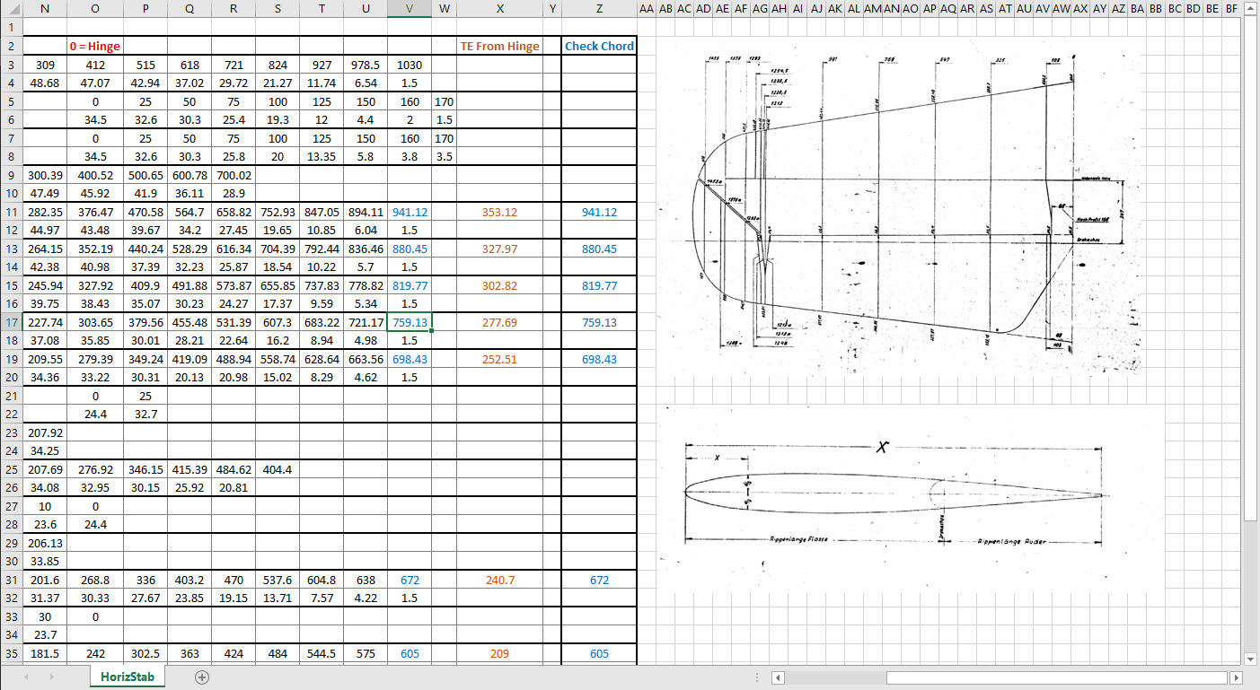
This project aims to document and preserve dimensional data for historical aircraft, currently working on models such as the P-47, FM2, and Grumman Goose, alongside two glider projects. Utilizing archival blueprints—often of suboptimal quality—we employ precise digital reconstruction techniques to ensure the accuracy of aircraft structural data. The goal is to support restoration efforts, research, and educational initiatives in aviation history.

3. Objectives:

  • Digitally reconstruct and verify the dimensional data of historic aircraft.
  • Provide comprehensive documentation for restoration, museum displays, and aerospace research.
  • Develop methodologies for extracting accurate data from degraded blueprints.
  • Expand the available reference library for aviation researchers and engineers.

4. Significance & Impact:

  • Historical Preservation: Ensures that legacy aircraft remain accurately documented for future generations.
  • Educational Contribution: Supports aerospace research institutions and museums with validated technical data.
  • Technical Innovation: Implements advanced CAD techniques to refine aviation blueprint analysis.

5. Methodology:

  • Collection and analysis of historical blueprints and microfilm archives.
  • Use of CAD software to recreate accurate aircraft structures.
  • Cross-referencing archival data with existing dimensional records.
  • Collaboration with restoration experts to validate findings.

6. Challenges & Solutions:

  • Suboptimal Blueprint Quality: Implement specialized image enhancement and measurement techniques.
  • Funding Limitations: Seek partnerships with aviation museums, historical organizations, and aerospace institutions.
  • Data Validation: Engage with experts to cross-check reconstructed aircraft dimensions.

7. Funding Request & Justification:

The project has been independently funded to date, but rising operational costs present financial challenges. Support is requested to sustain ongoing research, enhance documentation quality, and facilitate broader distribution to historical and aviation institutions.

8. Potential Collaborations & Sponsorships:

  • Aviation Museums: Partnerships for data preservation and restoration projects.
  • Educational Institutions: Opportunities for research integration and student engagement.
  • Aerospace Industry Experts: Validation and application of documented data.
  • Fellow Enthusiasts and Donors: Acknowledge contributions, engage in peer-to-peer discussion and provide technical support where applicable.

9. Conclusion:

This initiative offers a critical contribution to aviation history by preserving precise structural data of historical aircraft. With adequate funding and institutional partnerships, the project will continue advancing research and documentation efforts for aviation scholars and engineers.

—————————————————————————————————

Contact Hugh Thomson via email: hughtechnotes@gmail.com.

Messerschmitt: Bf109 Ordinates

Messerschmitt: Bf109 Ordinates:

I recently received an inquiry from a museum regarding ordinate datasets for the Bf109. As I previously mentioned in this earlier post the archive I have has a lot of data that was done by others…so I figured it was quite comprehensively covered.

Anyway, I decided to have a closer look and see what was actually documented and how well it aligned with known data. It turns out to be a bit of a muddle. Although the data is quite well presented I have uncovered a number of inconsistencies and anomalies which I will need to resolve.

8-109.000 G-2 Flugzeug Zuss 2

What I thought would be a quick response to an inquiry has initiated a much more intensive study which admittedly I had not planned for. I will go back to basics with this one, using the existing data as a reference and develop a new set of ordinate data for the Bf109 similar to how I approached the Mustang P-51 project.

I have already started with the Horizontal Stabiliser and part of the way through the Vertical. The tables will essentially be a reconstruction from the Messerschmitt drawings and then compiled to develop the X, Y, Z ordinates for transfer to CAD.

bf109


NAA P-51D Mustang: Front Fuselage

NAA P-51D Mustang: Front Fuselage

Following a recent inquiry, I have revisited the NAA P-51 Mustang project to develop the front fuselage and cockpit. This will be an extremely detailed and accurate model including fixings and rivet holes.

P-51D Early.png

The partial structure above is for the early P-51D version; note the instrument panel and support frame. There are also some minor differences with the other components, most notably the curved beam which has different end brackets for the early and late versions.

The 2 instrument panels depicting the P-51D versions, with the later version on the right. This will be a medium to long term project for which I will post regular updates.

NAA P-51D: Master Lines Plan

NAA P-51D Mustang: Master Lines Plan

The P-51D project is progressing well with further developments on the fuselage frame profiles. I now have a comprehensive Master Lines Plan incorporating additional information obtained from mathematical analysis, drawings, reference documentation and geometric developments. I have updated and remodeled the underside Oil Cooler Air intakes, canopy, windshield, rear fuselage and fuselage tail-end. As part of the remodel the groups of ordinates for each frame for the Oil Radiator Duct, Coolant radiator Duct and Removable Scoop are now contained on their own respective work-planes. This will make it much easier to micro manage the final mold lines.

Fuselage Master Lines Plan (P-51D overlaid on P-51 B/C):

2017-07-01_14-32-09

Test Lofts and developments:

2017-07-01_14-30-24

Front Views (note the Canopy Profile update from the previous article):


A month ago I was not sure how much could be achieved given the limited amount of information at hand but with due diligence and detailed research, it is quite amazing what can be accomplished.

With this template, it is now technically possible to accurately develop a CAD model for the entire fuselage structure and mechanical components for the P-51D, which would be great; but I often wonder what the value of such an undertaking would achieve, other than being a darn interesting thing to do and a test of CAD modeling skills.

Having achieved this significant milestone the time is right to conclude the work on the Mustang P-51D and P-51 B/C projects. I may continue with the P-39 project but as always I am keen to explore the options for the more obscure extinct aircraft as described in Operation Ark.

2017-07-01_00-15-20

If you are planning on developing your own Master Lines plan a good place to start would be with the 1000’s of ordinates points cataloged and recorded on the spreadsheets here: Mustang P-51B/C Ordinates which also includes the wing ordinates for the P-51D and vertical stabilizer.

NAA P-51D Mustang: Wing Ordinate Rev

NAA P-51D & B/C Mustang: Wing Ordinate Major Update:

Thanks to Roland Hallam, I am now in receipt of new verifiable information that has prompted a return to the P51 project and a major update to the wing ordinate data sheets.

2017-05-21_15-46-57

Many of the blanks have now been filled in and new additional information added. The above image is a snapshot of the work in progress. The groups highlighted in blue are checked verified dimensions, the red values are those that have changed and those areas remaining in white have prompted an interesting conclusion. Up until now, it was presumed that the wing profiles for the P51D and P51C were the same with the exception of the wing root, however, closer inspection would now suggest that a few rib locations are also slightly different which requires further investigation.

I am still working through the new information and dissecting what is relevant to the P-51D and the P-51B/C variants. This will probably take me a while to evaluate but I am confident that this will result in the most comprehensive dataset yet compiled for the P-51 wings.

I had not expected to return to the P51 project at this time but I’m sure you will agree this is an exciting development.

Bell P-39: Cockpit Glass

Bell P-39: Modelling Curved Cockpit Glass (Inv 2017)

Modelling the Cockpit glass can be a challenge to achieve the correct curvature and create the inevitable jogged and profiled edges.

P-39 canopy

The Bell drawing lists all the ordinates to enable us to create the profile sketches from which to derive the required basic shape with two areas worth extra consideration in respect to the rounded corners and the jog along the perimeter edge.

We developed the initial extruded surface from the contour ordinates and then simply extruded a sketch to trim this surface to the basic shape.

P-39 c1

The first thing we need to do is to fillet the corners. In Autodesk Inventor we cannot fillet a single surface, though we could use various techniques to do this we decided instead to Thicken the surface an arbitrary amount ( it does not much matter how thick it is) and then apply a fillet of each corner of the solid which ensures correct tangency.

P-39 C2

The jog along the edges is a bit tricky, given the nature of the surface. One way of doing this would be to sketch the jog profile and sweep the profile using the edge as the path. We tried this in several configurations but the result was not consistent.

To solve this we need to consider what a solid comprises off in order to rethink our strategy. A solid is essentially a series of closed surfaces that are used to contain the solid properties. With this in mind, we started by offsetting the top surface to create a copy at the desired jog dimension inward. Along the edge of this new surface, we sketched a circle with a radius the same as the jog flat dimension and swept this along the perimeter of the new surface.

P-39 C20

By using a circle profile for the sweep we ensure that the resulting flange; which is trimmed from the copied surface; will be a consistent width throughout its length. Now we have a surface representing the exact dimensions of the jogged top face at 3/8 inch. We do something similar for the top surface which is selected from the solid with the circle set to a bigger dimension to facilitate the jog transition curves. This time simply trimming to remove the edge width.

p-39 c21

This gives us 2 surfaces, the lower surface for the top face of the jogged flange and the second, the actual main surface for the top of the canopy glass. To fill the resulting gap between the surfaces we used a patch surface.

P-39 CX

We have trimmed the surfaces of the solid body thus breaking the solid cohesion leaving a number of orphaned surfaces which can now be deleted. To finish we would stitch the surfaces and then thicken to the required amount.

p-39 c12

To achieve a smooth transition when applying a patched surface between 2 surfaces a good result can often be achieved by using the tangency option relative to each joining surface. In this particular instance, the patch size was too small to do this so instead we applied fillets to achieve the same results.

A Note on Curvature:

P-39 Canopyx

It is absolutely critical to manage the curvature of the sketch profiles prior to lofting to ensure the best possible surface. This usually requires marginal adjustment to the ordinate dimensions; generally fractions of a millimetre; to achieve a good result.There is a small shoulder on this glass panel thus accounting for the slight edge deviation. To improve further the definition of the finished surface we can convert to a freeform surface which will derive a new surface with G2 curvature.

P-39 Cockpit Glass

Another Quick Tip:

Sheet metal flanges are restricted in Inventor to straight edge segments whereas with Solidworks we can actually create a curved flange where there is continuous tangency. One workaround in Inventor is to sweep a profile along the edge of the sheet metal part to create a flange or alternatively use the Ruled Surface feature.

P-39-1

This feature provides a few functions for extending surfaces either perpendicular or tangential to an existing surface. In this example, we simply select the default and create a perpendicular edge without requiring additional sketches.

Thicken the resulting surface, convert to sheet metal part and apply a traditional flange!

Bell P-39: Wing Trailing Edge

Technote: Bell P-39 Wing Trailing Edge Calculation.

The root wing profile for the P-39 is based on the NACA 0015 (4-digit series).

p-39 wing TE

The Bell P-39 archive contains ordinate data for the fuselage, tail, stabilisers, cowls and so on but sadly the main ordinate plan for the wings is missing. However, we do have some ordinate data including a mid wing profile section and of course the front, rear and aux beams. We also know the root wing profile is based on the NACA 0015 which collectively provides enough core information to develop the wing structure.

The “baseline” NACA 0015 has a non-zero trailing edge thickness relative to the chord length. Just working from the generic geometry formula we end up with a large trailing edge thickness which is greater than that specified by Bell.

The baseline NACA 0015 airfoil is described by the function:2016-08-23_04-27-34

In order to achieve a degree of control over the resulting trailing edge thickness we only need to adjust the fourth coefficient in the polynomial slightly.

xyz

The above amendment will give a zero thickness at the trailing edge. The actual value we were looking for was 0.03in radius which was achieved through trial and error with the fourth coefficient value set to 0.1024.

  • x = coordinates along the length of the airfoil, from 0 to c (which stands for chord, or length)
  • y = coordinates above and below the line extending along the length of the airfoil, generally defined as either yt for thickness coordinates or yc for camber coordinates

The final profile was checked against known ordinates from the fuselage data.

The information here was sourced from a white paper written by WeiHei, Francisco Gomez, Daniel Rodriguez and Vasilis Theoflis.


Bell P-39 Airacobra: Fuselage

Bell P-39 Airacobra: Fuselage

This is an update on the P-39 project. I have actually been drifting between this and the P-51 Mustang as a number of inquiries have come in regarding the ordinates and various questions on the Oil Cooler model and landing gear mechanisms; which has been an interesting diversion.

Getting back on topic, I thought it may be prudent to write a quick update on what I am doing with the P-39 Airacobra and where I hope the journey will take me.

I have of course continued working on the ordinate data spreadsheet which is derived from the part drawings themselves. This serves as a check whilst I am developing the structure. The 3D models are being developed in context, i.e the individual part models are located to the 3D spatial ordinates relative to a single datum so when I plug these into the assembly they will import to the correct 3D location thus negating the requirement for constraints.

2016-08-12_22-48-54

This is the first time I have worked this way as I usually just model the part and then constrain to the corresponding items in the assembly, but this is usually dependent on the quality of the assembly scans to clearly identify and ensure correct alignment of the parts. As we all probably know these scanned files are the most likely to have problems with legibility. In many respects having the part files modelled relative to ordinates in 3D space ensures that the parts line up correctly and I don’t have to worry too much about the quality of the assembly scans.

P-39 Airacobra Fuselage

The P-39 main assembly drawings are actually not too bad as the image above shows. This is a scrap view of the fuselage Longitudinal, comprising many small parts all riveted together to form the assembly. The area in red is where I am working at the moment; which is a major node; just aft of the engine bay; where the many struts and braces overlap on both sides of the stiffener plate. The following image gives you some idea of the detail to which this is being developed.

P-39 Airacobra Fuselage1

The pilot holes for the rivets are unique to each individual part and just like the real process of construction these holes will be match drilled to all the other corresponding parts in assembly.

Modelling the complex parts and locating all those holes takes a lot of time but I believe the end result will be worthwhile. With this degree of accuracy you could just about build one of these aircraft from scratch!.

Quick Technote: P-39-01
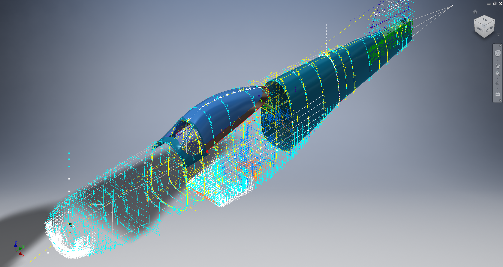
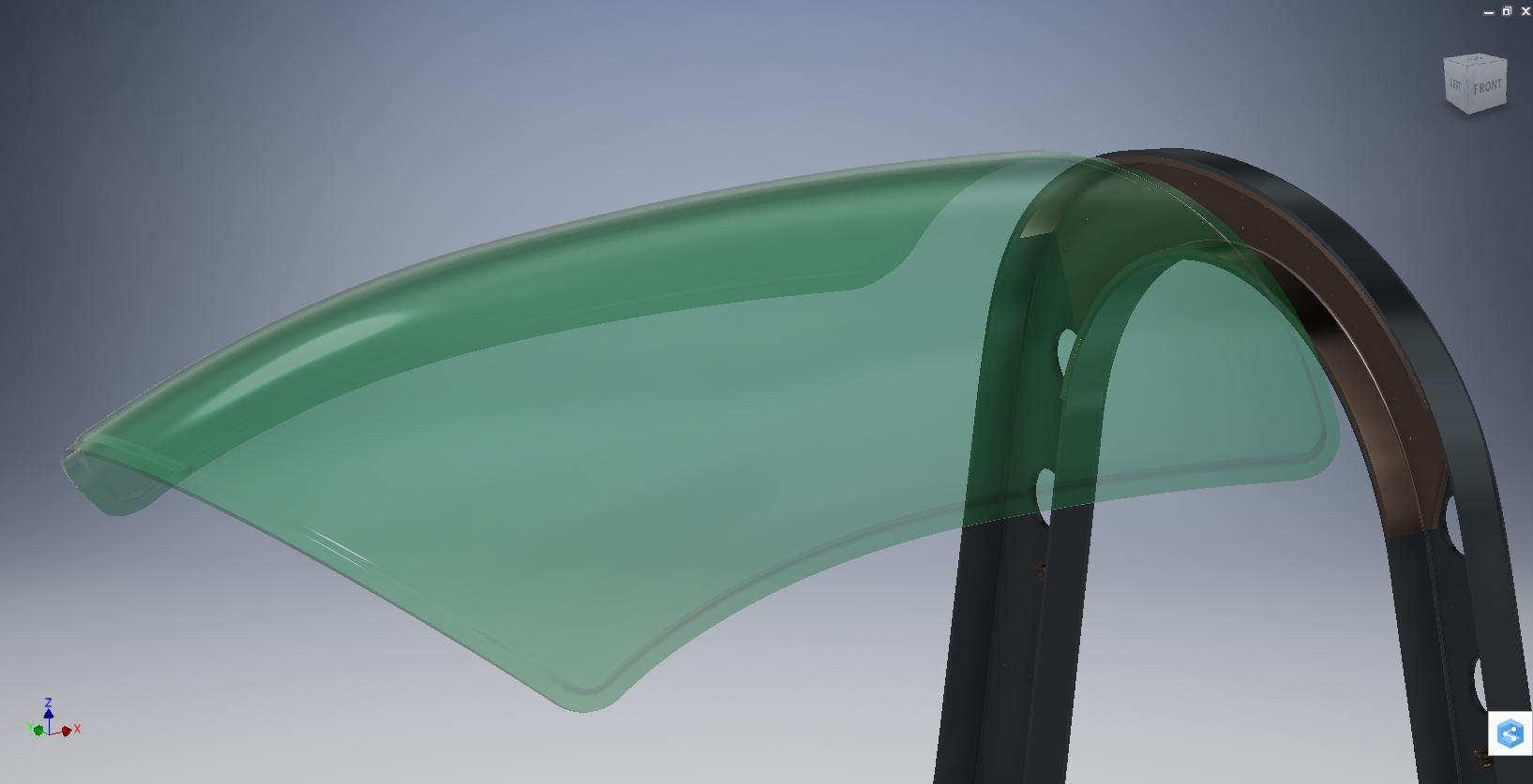
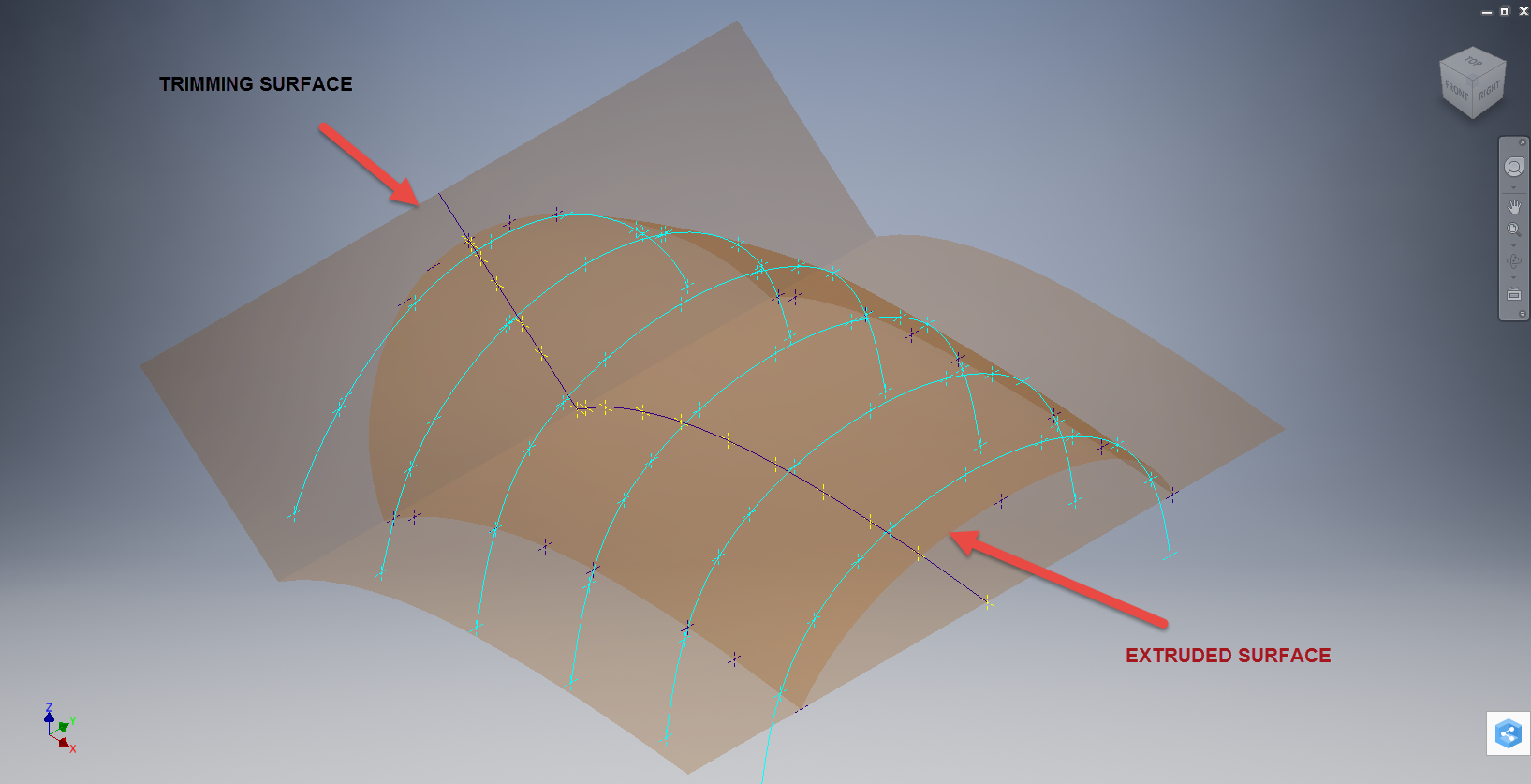
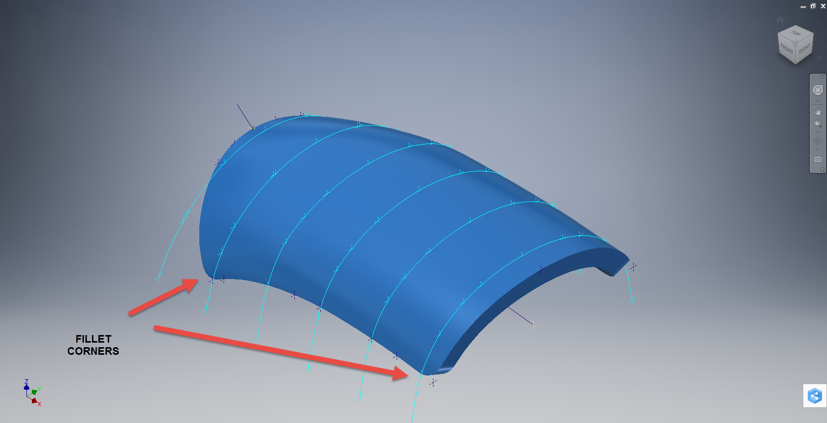
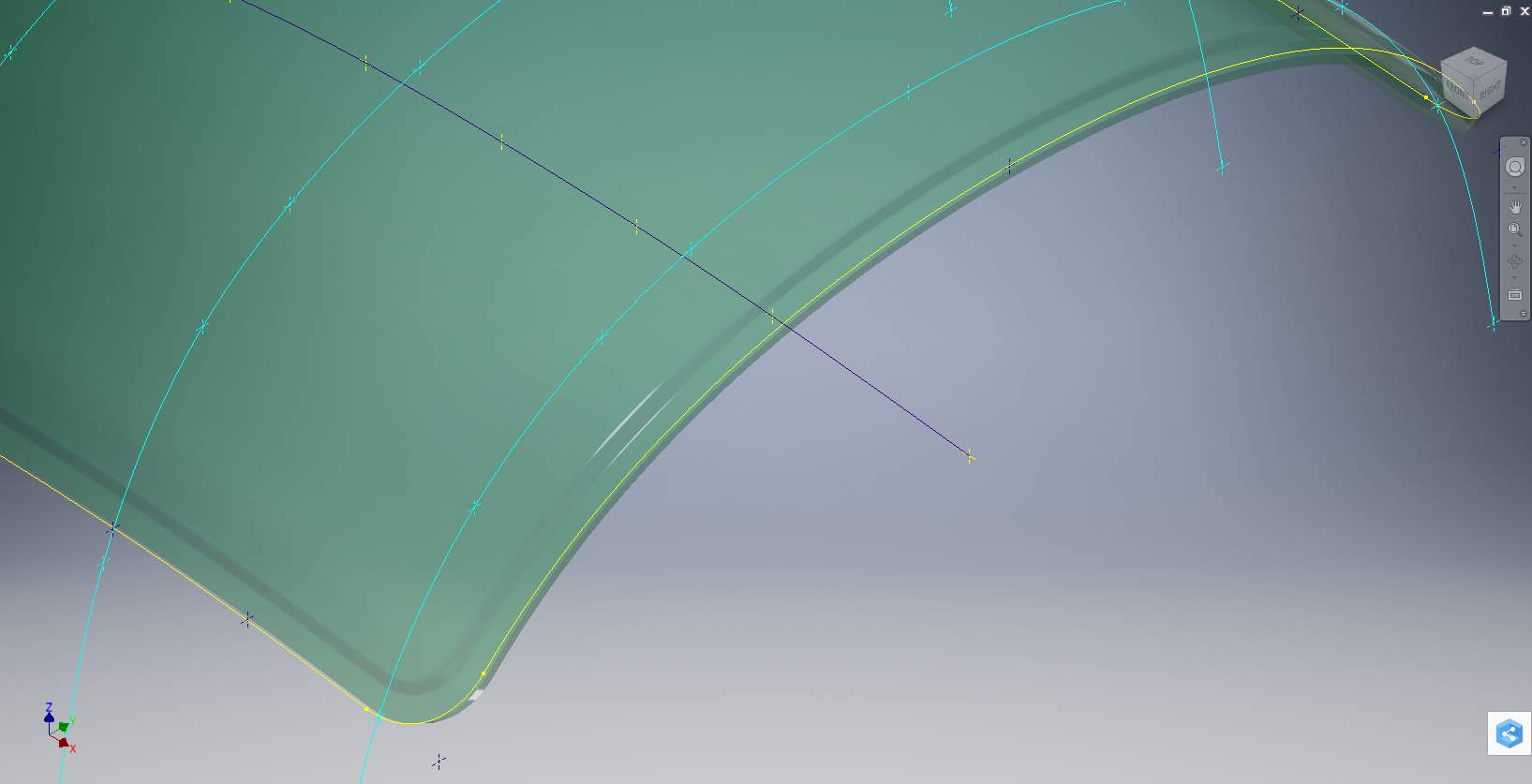
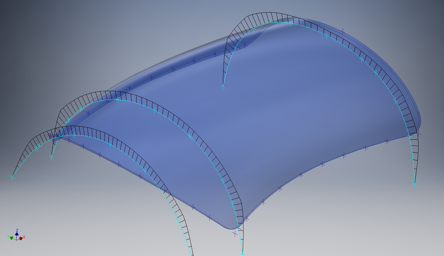
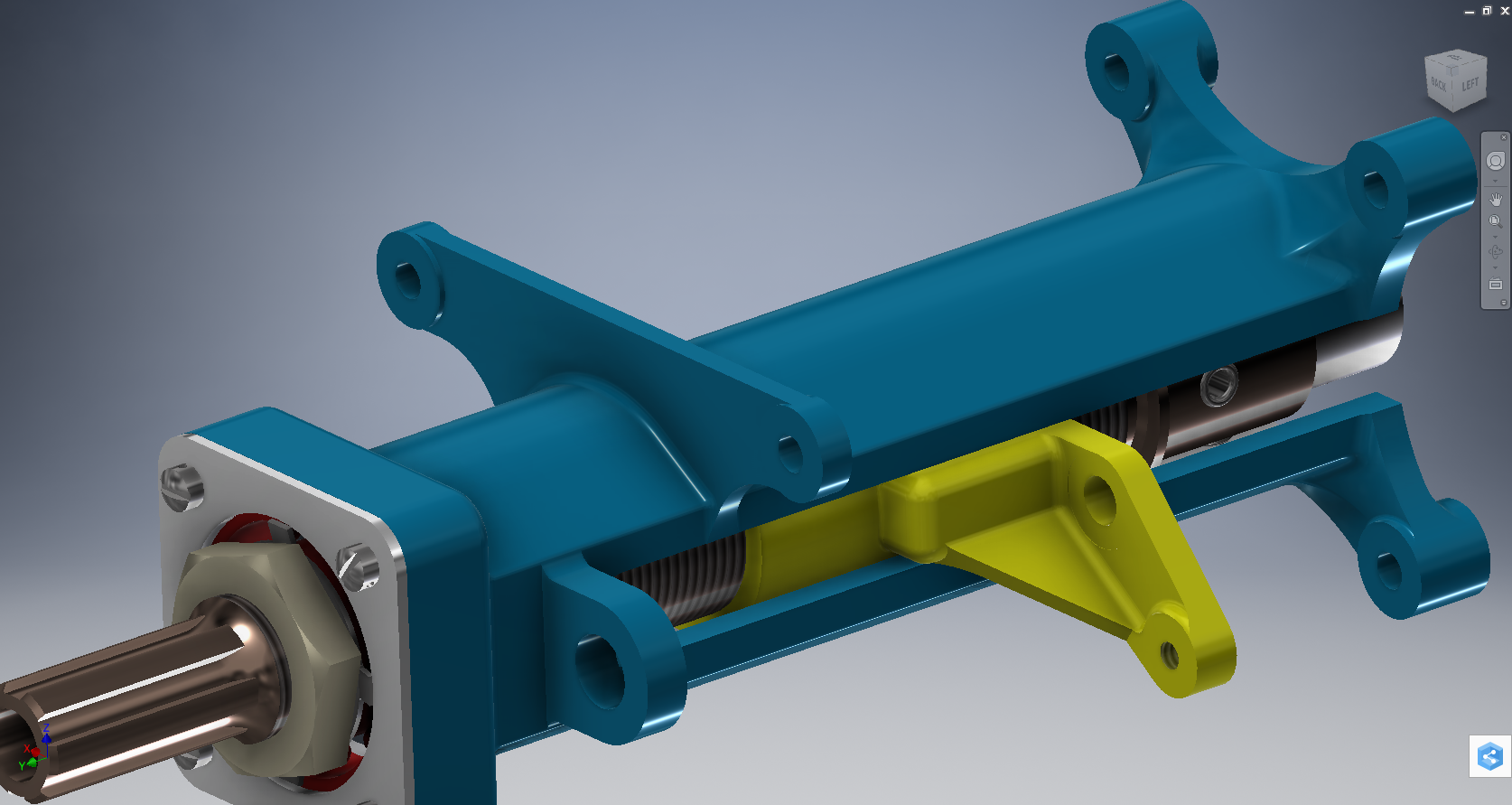
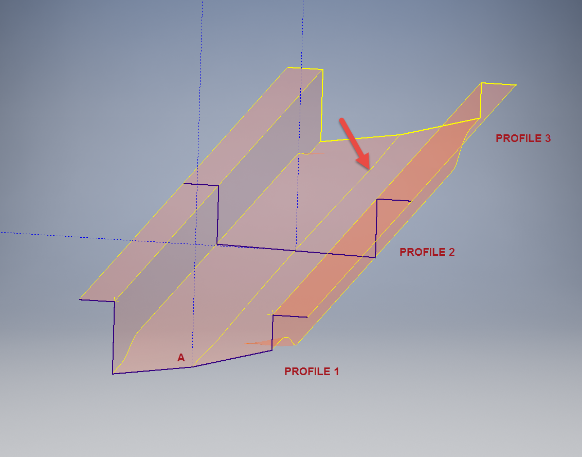
This is the lower level fuselage cross member that has a built in twist to align with the connecting frames at both ends. The model consists of 3 profiles with the 2 outer ones containing a small angular deviation in the centre at point A. Normally I would loft the profiles to create the finished surface but this projects the deviation throughout the length giving us 2 surfaces; which does not look good.

I therefore deleted the resulting 2 base surfaces and simply replaced them with a boundary surface. I’m sure you will agree the result is a much smoother gradation of curvature; that matches expectations.


Bell P-39 Airacobra: New Project

Bell P-39 Airacobra: New Project

Bell_P-39Q

I recently received a set of the P-39 scanned blueprints for the Bell P-39 Airacobra. An underrated aircraft not popular with the Americans or Brits but was very successful with the Russian air force on the Eastern Front, particularly the 9 GIAP, known as the ‘Regiment of Aces’. There are plenty online resources documenting the amazing history of this aircraft, suffice that I would find it difficult to add anything significantly new here.

The set of drawings; approx 11,000; are actually very good quality scans of which I have spent some time looking through and randomly modeled a few items…like this part for the Landing gear nose wheel travel indicator.

p-39 airacobra

Most aspects of the main structure are also well covered with the ordinates included on the detail drawings and not as a separate sheet. This could be an interesting project and although not entirely a rare aircraft; as we still have a few flying examples and static displays; I do think it will be a worthwhile aircraft to develop. Most of the examples unfortunately are based in the US but there is one on display in Finland, for which a visit is on my to-do-list later this year.

I’ve played about with modelling some bits and reviewed the drawing organisation. I now need to get down to some serious work starting with reverse engineering the ordinate data on the drawings to establish an ordinate record and create the mold lines.

Sample: Ordinate data copied from manufacturer drawings maintaining original format.

P-39 Ordinates

2016-07-17_04-10-39

This Dataset is then restructured in a separate worksheet to derive the X,Y,Z coordinates for input into CAD.

The ordinates are important for modelling so we can loft the surfaces to check the angle of the frame flanges for correct alignment and also enables us to model parts in the 3d space sufficient that their location in the final assembly is already determined.

2016-08-17_04-39-38

This is definitely a long-term project for which I will post updates on progress, though not quite as regular as I have done in the past for previous projects.

Other project Ordinates:

P-51 Mustang available here: Mustang P-51 B/C Ordinates

Ta-152 available here: FW 190 & Ta152: Ordinates

The Journey

The Journey:

This blog has been about the journey cataloging my passion for historical aviation design and construction. Its about the geometry; the ordinates and plans, about the designs and construction; from wood and canvass to full metal and alloy and the inspirations for the designs. The sheet metal work, the manufacturing, the mechanics, materials, electrics and hydraulics.

Its been an interesting time studying the different aircraft construction techniques and design methods. The different approaches to how different designers organise and develop the designs on the drawing board, sometimes accumulating 100o’s of drawings for a single aircraft…an admin challenge that even today would be quite daunting.

Not all my work has been published here, only a few examples that I think may be of particular interest. The evolution of the FW-190 to Ta-152, the various marks of the Spitfire, the early design characteristics for the Tiger Moth, the Mustang P-51 conic research and mathematical analysis culminating in a broad spectrum of research material that lays the foundation for the next chapter in my work.

I have learned a lot from this work which has been both challenging and frustrating. Its tested the limitations of my knowledge and the CAD systems we have come to rely on so much in our designs today.

Not many of the archive drawings sets I have are representative of a complete aircraft, often missing key information or simply illegible; though the latter sometimes can be overcome by studying other aspects of the design. I am often asked if I would consider creating an entire aircraft design in CAD that could actually be manufactured and whilst the answer is of course yes I would be reluctant to spend the considerable time required for any aircraft for which we have many flying examples.

Having said that Operation Ark was setup to undertake such a task for an extinct or rare aircraft depending on availability of sufficient design data. This work is still in progress and will take a while to resource, evaluate and fund such a project.

In the interim I have received a new set of archive material for an aircraft that was used extensively by Russia on the Eastern front which will be featured here in a few months time.

For now there wont be many updates but please do drop me a line as its always good to hear from the many readers of this blog about their own experiences in the exciting world of historical aviation.