Bell P-39: Fold Over Flange

Technote: Bell P-39 Fold Over Flange.(Inventor 2017)

This a quick technote to highlight an issue that we sometimes come across with creating flanges in Inventor when one part is sloping away from the other.

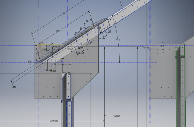
The part we are working on is shown on this scrap view from the Bell drawings. This flange is folded over onto a sloping top plate from the side plate that is at an angle of 105 degrees.

P-39 Oil Cooler Main1

The issue relates to the reference edge selections that will determine whether or not we obtain a smooth transition from the side plate to the new flange.

P-39 COOLER MAIN5

When I first did this I selected the outside edge of the side plate to align the flange sketch. This was not satisfactory due to the notches; that are perpendicular to the side plate; influencing the creation of the eventual flange bend which gave us a rather awkward and untidy bend transition…definitely not good.

So I recreated the sketch; this time aligning with the inside edge of the side plate; which resulted in a smooth transition bend to both notched areas as shown below.

P-39 COOLER 4

Occasionally when creating flanges the selection of which edge is referenced can make all the difference in achieving a satisfactory result. Use the sheet metal Face command to create a flange based on a 2D sketch as we have done here.

I should note that those notches are bigger than they need to be at this stage. I normally develop these complex models using a generous radius until I have completed the construction. Once I have achieved a satisfactory model and everything aligns correctly then I can go back and adjust these notches to a minimum size.

Progress Update:

I have included the rear fuselage section contour lines for reference. Will probably have to leave this project for a few weeks as I really need to spend some time sorting out my garden that is slowly resembling a jungle!

P-39 Aug21

37mm Gun Mount & Rudder Cable Guide Pulley.

Bell P-39 Airacobra: Fuselage

Bell P-39 Airacobra: Fuselage

This is an update on the P-39 project. I have actually been drifting between this and the P-51 Mustang as a number of inquiries have come in regarding the ordinates and various questions on the Oil Cooler model and landing gear mechanisms; which has been an interesting diversion.

Getting back on topic, I thought it may be prudent to write a quick update on what I am doing with the P-39 Airacobra and where I hope the journey will take me.

I have of course continued working on the ordinate data spreadsheet which is derived from the part drawings themselves. This serves as a check whilst I am developing the structure. The 3D models are being developed in context, i.e the individual part models are located to the 3D spatial ordinates relative to a single datum so when I plug these into the assembly they will import to the correct 3D location thus negating the requirement for constraints.

2016-08-12_22-48-54

This is the first time I have worked this way as I usually just model the part and then constrain to the corresponding items in the assembly, but this is usually dependent on the quality of the assembly scans to clearly identify and ensure correct alignment of the parts. As we all probably know these scanned files are the most likely to have problems with legibility. In many respects having the part files modelled relative to ordinates in 3D space ensures that the parts line up correctly and I don’t have to worry too much about the quality of the assembly scans.

P-39 Airacobra Fuselage

The P-39 main assembly drawings are actually not too bad as the image above shows. This is a scrap view of the fuselage Longitudinal, comprising many small parts all riveted together to form the assembly. The area in red is where I am working at the moment; which is a major node; just aft of the engine bay; where the many struts and braces overlap on both sides of the stiffener plate. The following image gives you some idea of the detail to which this is being developed.

P-39 Airacobra Fuselage1

The pilot holes for the rivets are unique to each individual part and just like the real process of construction these holes will be match drilled to all the other corresponding parts in assembly.

Modelling the complex parts and locating all those holes takes a lot of time but I believe the end result will be worthwhile. With this degree of accuracy you could just about build one of these aircraft from scratch!.

Quick Technote: P-39-01This is the lower level fuselage cross member that has a built in twist to align with the connecting frames at both ends. The model consists of 3 profiles with the 2 outer ones containing a small angular deviation in the centre at point A. Normally I would loft the profiles to create the finished surface but this projects the deviation throughout the length giving us 2 surfaces; which does not look good.

I therefore deleted the resulting 2 base surfaces and simply replaced them with a boundary surface. I’m sure you will agree the result is a much smoother gradation of curvature; that matches expectations.


2D Draughting to 3D Models

2D Draughting to 3D Conversion

2d to 3dTechnical drawings, detailing the specifics of your design can be critical for the communication both internally and externally. We can transform your 2D CAD or fully dimensioned legacy paper drawings to 3D Models using our experienced engineers to ensure drawings are 100% accurate and adhere to the most relevant standards and protocols.

3D Cad models will be fully inclusive of manufacturing tolerances as specified. New 2D drawings will be derived from the 3D model, dimensioned and denoted as original.

Attributes and BIM IFC data can be incorporated according to your engineering and company standards for Structural, Mechanical, Building Services and Equipment projects.

We normally use the Autodesk Inventor but are equally capable with all the Autocad based products from which we can provide native format model files or various other formats to suit your requirements, including DWG, IFC, STEP and STL.

We can provide CAD modelling services for your restoration project, adhering to all appropriate standards and design specifications.exit

First Post and Introduction

First post on my Blog. 3rd Sept 2008.

It seems logical that my first article should be an introduction and tell you something about myself:

In my career I have progressed from a draughting apprenticeship in 1976 through 30 years of engineering with over 20 companies worldwide in various positions of responsibility and disciplines. My recent experience is perhaps more prevalent to this blog as it encompasses about 12 years of Cad management and Consultancy for major multi-discipline design engineering companies.

I was fortunate in 1985 to be first introduced to CAD design with a training course I undertook to learn Pafec Dogs – during this course the lecturer received a copy of Autocad – which was amazing as it was capable of running on a 386 PC!. This got me started in a long time association with the Autodesk products from the 2D in the 80s and then 3D in the early 90s through to the present day.

I have always been fascinated with the design and construction of the WW1 and WW2 fighter aircraft. In 2009 I had a lot of spare time on my hands so I decided to search for historical aviation resources to find information that would assist me with my research. Fortunately I came across a number of archive resources and I was able to study and develop some of the fine details of these aircraft utilizing my CAD and engineering skills.

So hence this blog!

In addition to my interest in historical Aviation & 3d Cad I occasionally venture into other fields of engineering, some of which may be featured here.

I hope you enjoy reading this blog.

Best Regards

Hugh