Technote: Divide a Line in Inventor:
Dividing a sketch line in Autocad is very straightforward and the question is often asked how this can be done in Inventor. There are a number of options to do this which I will explore and then I will discuss an application where the solution is not so obvious.

Where you have a known length and you wish to locate a point at 20% of the LENGTH it is simply a matter of applying the formula “LENGTH*0.2” for the dimension value. Another option is when you want to divide the line into 5 equal portions then you can use the RECTANGLE Pattern command. You first set the number of points, expand the dialogue and select FITTED; you will then need to select the line dimensions or measure as I have done here for the value.

Another way of doing this is to draw five line segments in succession and apply an equal constraint to each one. For the above; the length is a required parameter, so what do you do when you don’t actually know the length?
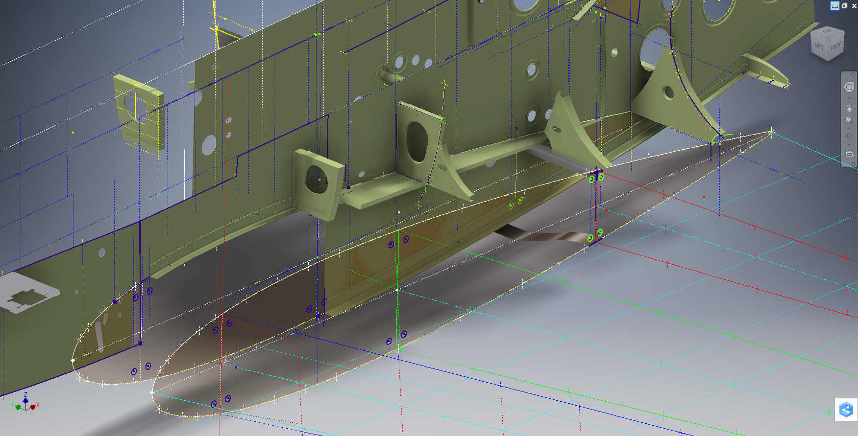
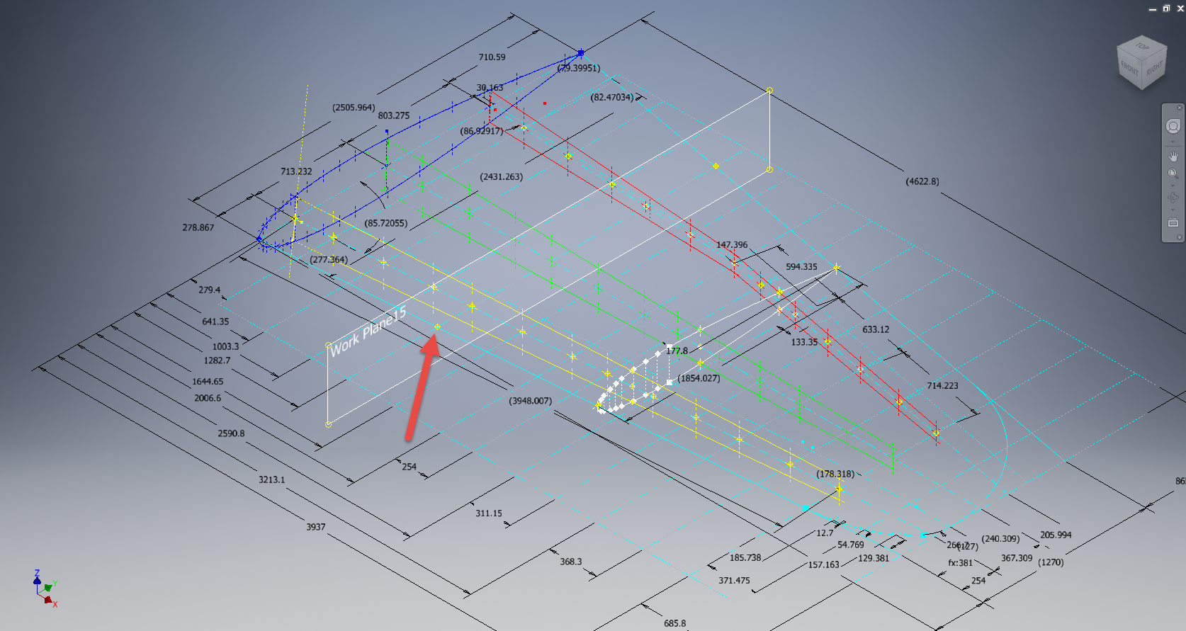
The following example is the P-38 Lightning Horizontal Stabiliser tip for which I wanted to document the ordinate points for the ribs. The ribs perpendicular to the stabiliser axis are known dimensions based on the standard profile however I also needed to record the profile dimensions of the ribs set at an angle to the main axis. Admittedly the Lockheed archive does contain a number of ordinate profiles for the canted ribs where unfortunately the majority of dimensions are illegible.

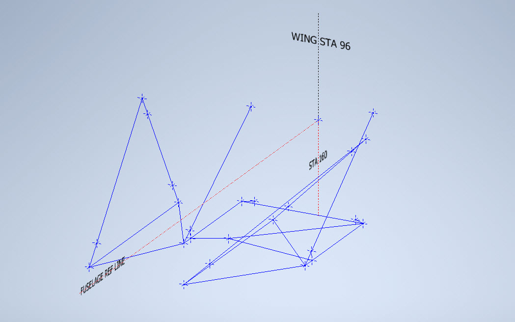
I like to record numbers so it should come as no surprise to those that visit this blog regularly that I was keen to tabulate the ordinate profiles for these canted ribs. The above image shows a number of magenta profiles which are the rib templates illustrating how the surface converges towards the tip extents. Incidentally, the diagonal lines on the main rib profile actually have a purpose…as you view the stab tip on the elevation you will notice that the ordinate points (projected) align with those diagonals.

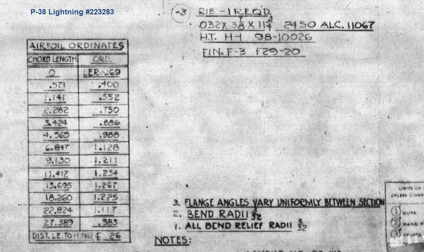
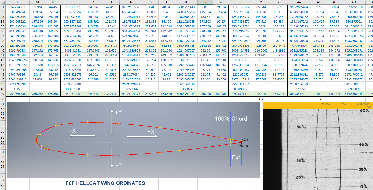
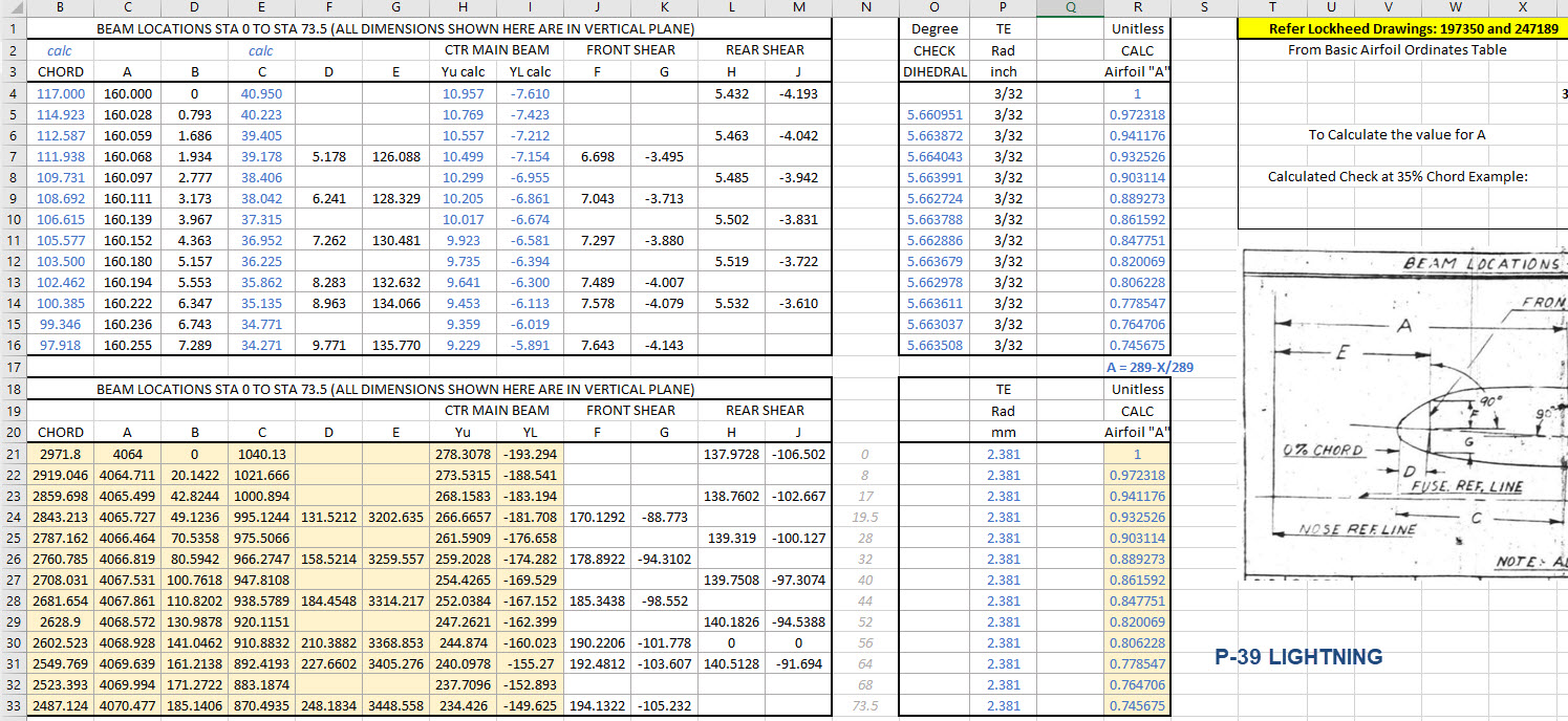
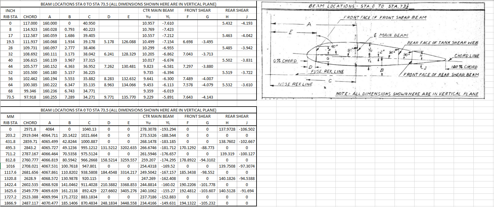
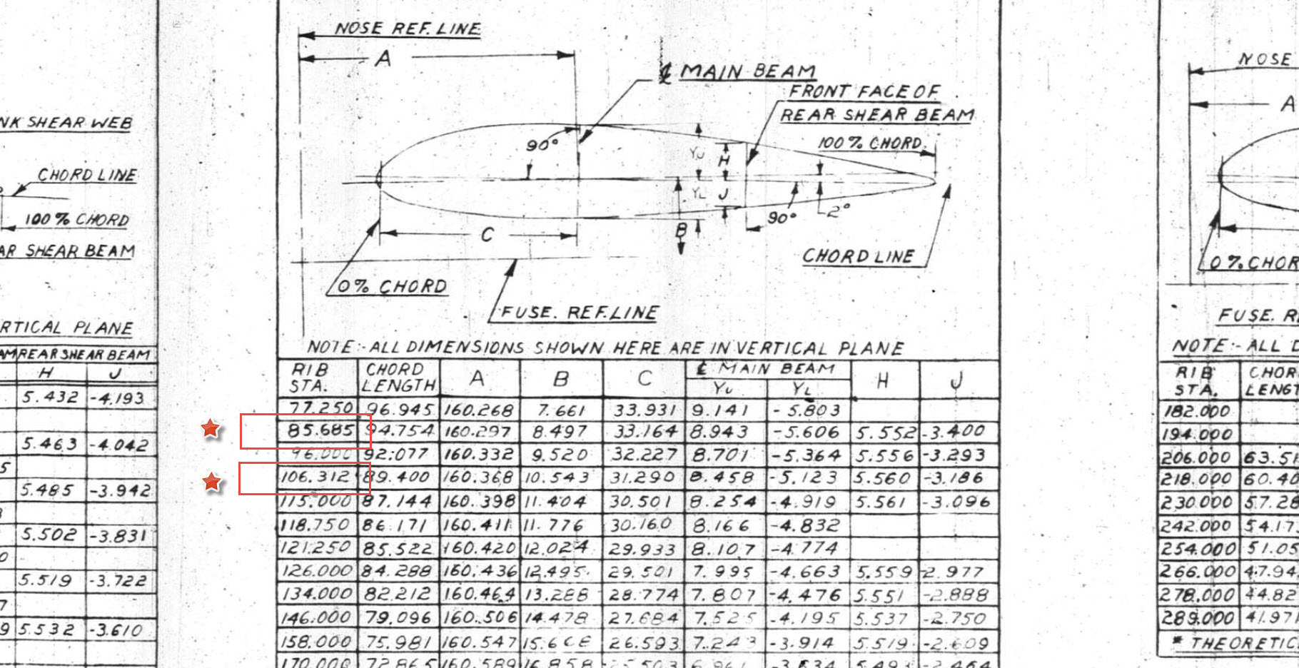
Getting back to the main subject. The wing rib and horizontal stabiliser ribs follow industry-standard percentage increments for defining the ordinates as shown in the following image. Now we are getting to the main topic…where I wanted to transfer the ordinate locations for the perpendicular ribs to define the ordinate profiles for the canted ribs.

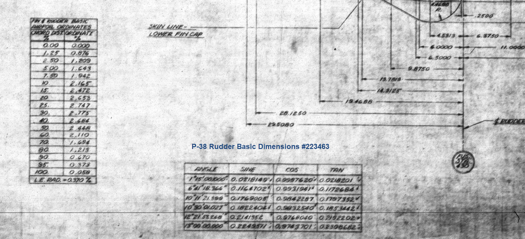
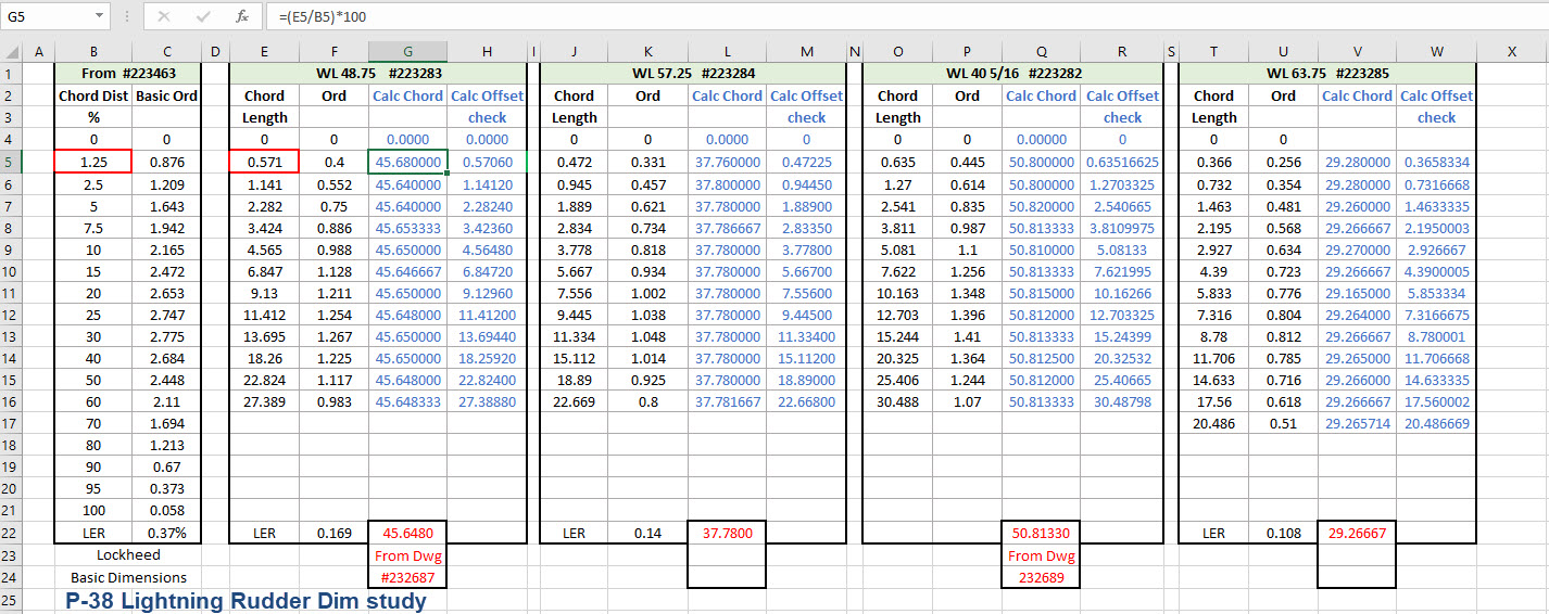
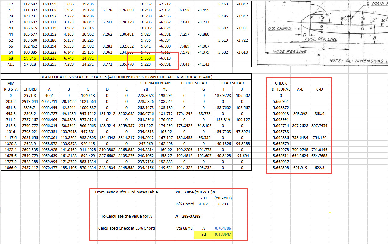
The Horizontal stabiliser ribs are based on the NACA 0010 airfoil profile which is listed as per the Lockheed drawings in the table on the left. The column on the immediate right is the calculated values to improve accuracy which also verifies the recorded data. The table on the right is the transposed calculated values for the main perpendicular Horizontal stabiliser rib with a chord length of 45″.

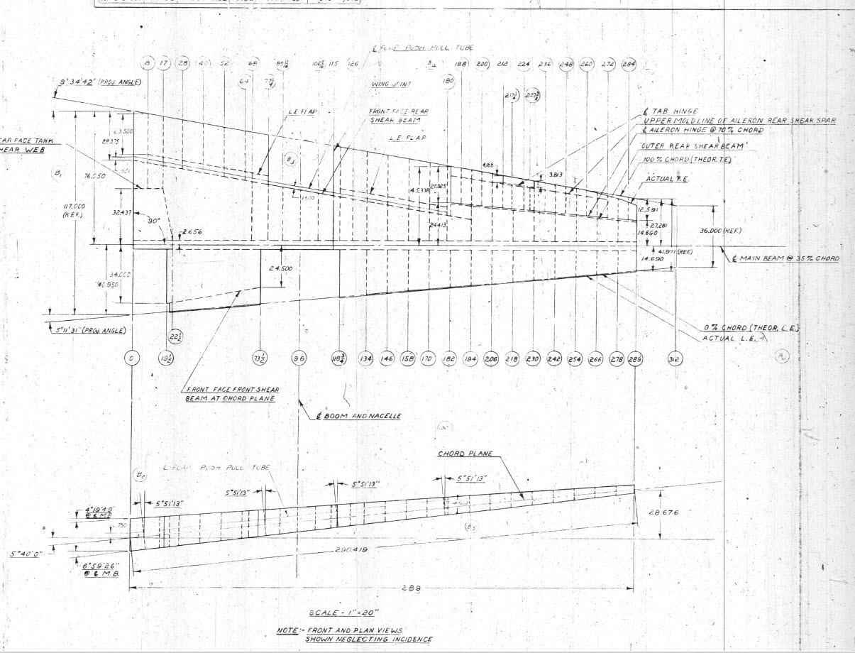
The above image is the plan view for the Stabiliser tip which shows the centres for the canted ribs and over to the right a number of red vertical dotted lines indicating the position of the reference perpendicular rib profiles. Between those ribs is a blue dotted line with a small circle indicator which is actually the main subject of this article.
The easiest way of defining the canted ribs is simply to loft the known perpendicular profiles and cut along the axis of the canted ribs…it definitely is the quickest way of doing this. However, that leaves a lot of miscellaneous activities in the cad model which just adds clutter.
Transposing the location of percentage increments from the rib table ordinate table to the canted ribs is done like this.

The perpendicular profile chord is the blue dotted line and the canted rib is the red centre line. The LENGTH is the chord length and the dimension A is the percentage increment on that line that we need to find the comparative intersection for on the cant rib. At this point, we do not know the LENGTH as this is dependent on the line position relative to the cant rib at whatever percentage increment we chose.
As mentioned at the start of this article for say a 20% chord dimension we could simply draw 5 lines in succession and apply an equal constraint and so on for the equal divisible portions…but that is not very practical.
So what we do is to locate the template rib line at any arbitrary point on the cant rib and then dimension the length…it does not matter at this stage what the dimension is. Now, this is the key thing we must do…select the LENGTH dimension and change it to a Driven Dimension. Now define the percentage increment (multiplied by Length) you wish to interrogate from the NACA table above and the template rib line will automatically relocate to a position where the Dim A is actually the percentage dimension you define of the total chord length. The software calculates the correct length according to the parameters specified.
An example would be where you specify 15%: you would write “0.15*D20” where D20 is the Driven Dimension.
I have included in the ordinate spreadsheets a table that will calculate the ordinate rib offsets depending on the chord length derived from the above exercise.

You then simply transfer those ordinate offsets to the intersection point of the cant rib. It really is quite clever when you think about it…you are asking the software to define the length of a line based on a percentage value relative to another canted line within boundaries specified by the arc.
Of course, I did not have to do this for all the cant rib offsets just the ones that were missing from the Lockheed drawings.
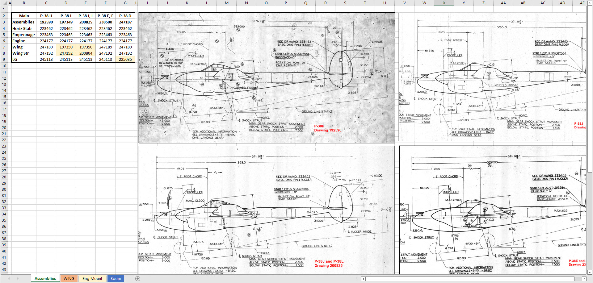
The P38 Lightning project is now finished. Only known dimensional data is included in this study. The engine Nacelle and Carb intake are omitted due to lack of dimensional information…however the creative among you will find it straightforward to interpolate fairly accurate profiles from the known information incorporated in this model and accompanying spreadsheet dataset.


Drop me a line at hughtechnotes@gmail.com


 The original formula for one of the constants “P” is given as shown (1). If we enter the formula as prescribed in a hand calculator it will evaluate correctly but will not work correctly in Excel in this format. So we need to tell Excel to essentially divide everything in the top line by everything in the bottom by adding parenthesis as shown (2).

