Technote: P-39 Door Handle CAD Solution

Technote: P-39 Door Handle CAD Solution:

This little part at first glance seems fairly straightforward, but there are a few caveats.

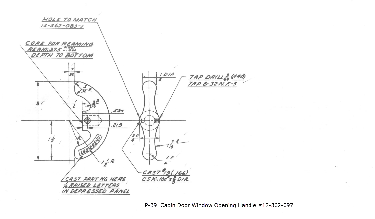
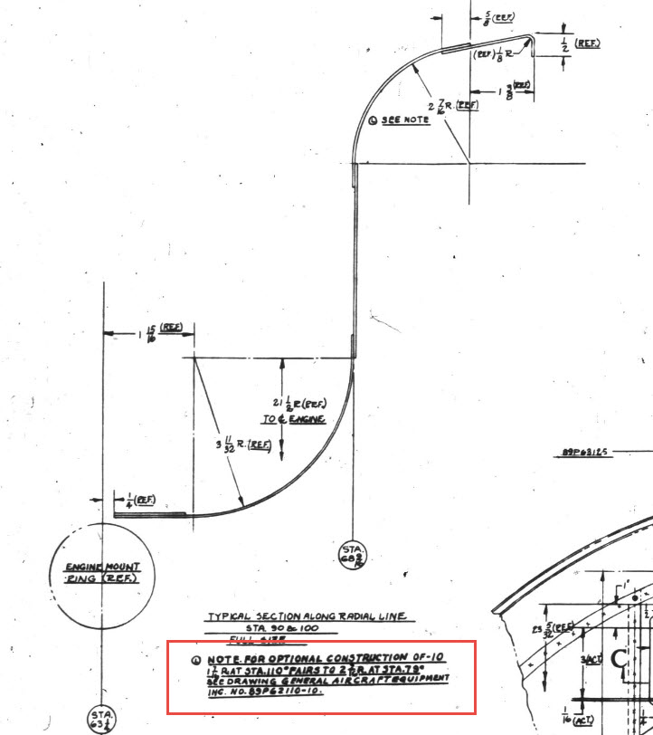
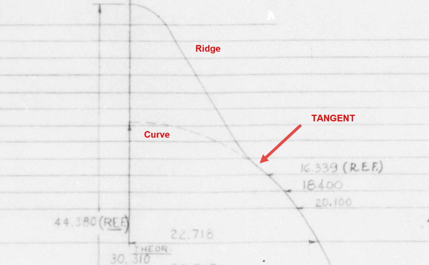
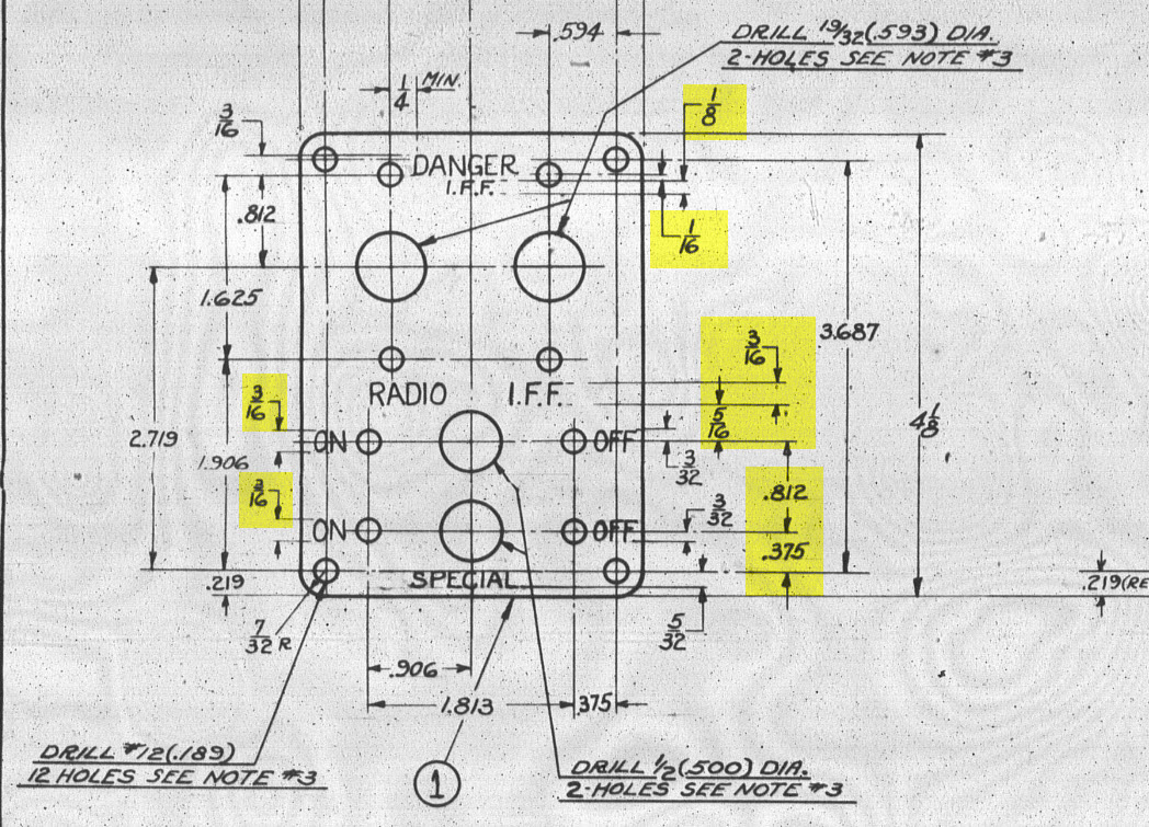
It has been a while since I specifically wrote a CAD solution Technote, and this seemed to be an ideal subject for surface modeling and 3D sketching. The dimensions define the outline for the front view, which is fine, and the plan view, which details a thinning of the handle cross section.

The thinning of the handle occurs in a specific plane as indicated in the plan view, while the front view maintains a consistent full depth diameter. Before diving into the modeling process, it’s important to pause and consider how to approach this design. Typically, my first step involves sketching out what is already known, which helps clarify the information we still need to gather. This initial sketching phase is crucial for laying the groundwork for an effective modeling strategy.

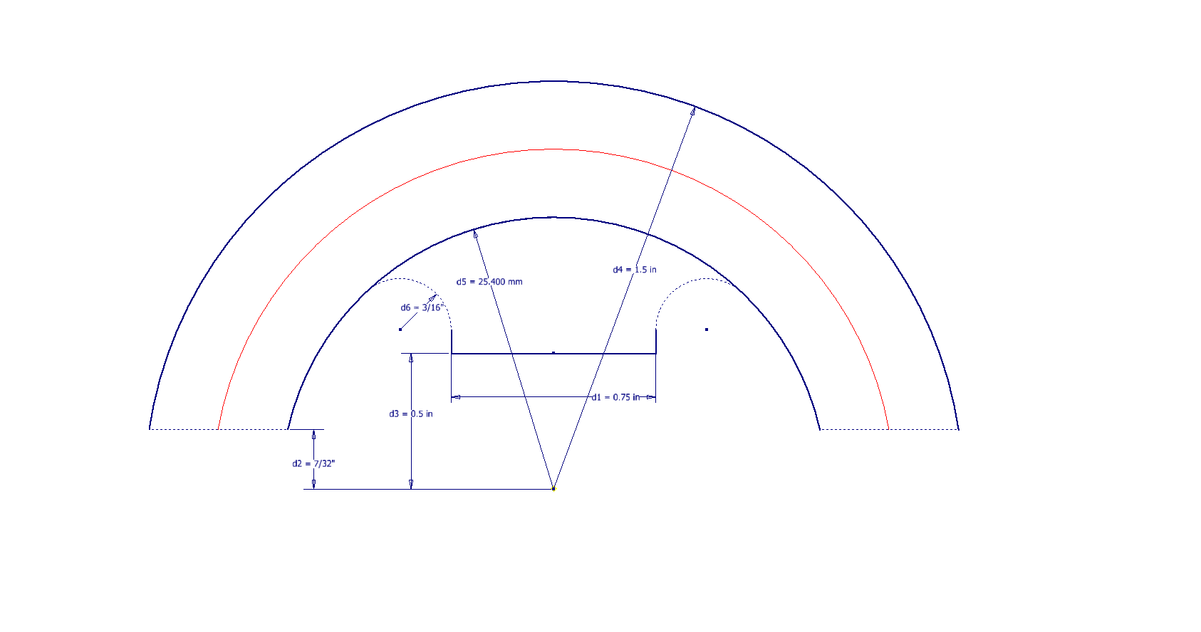
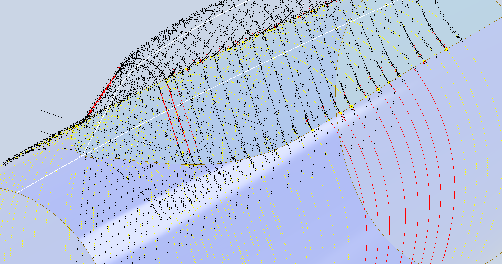
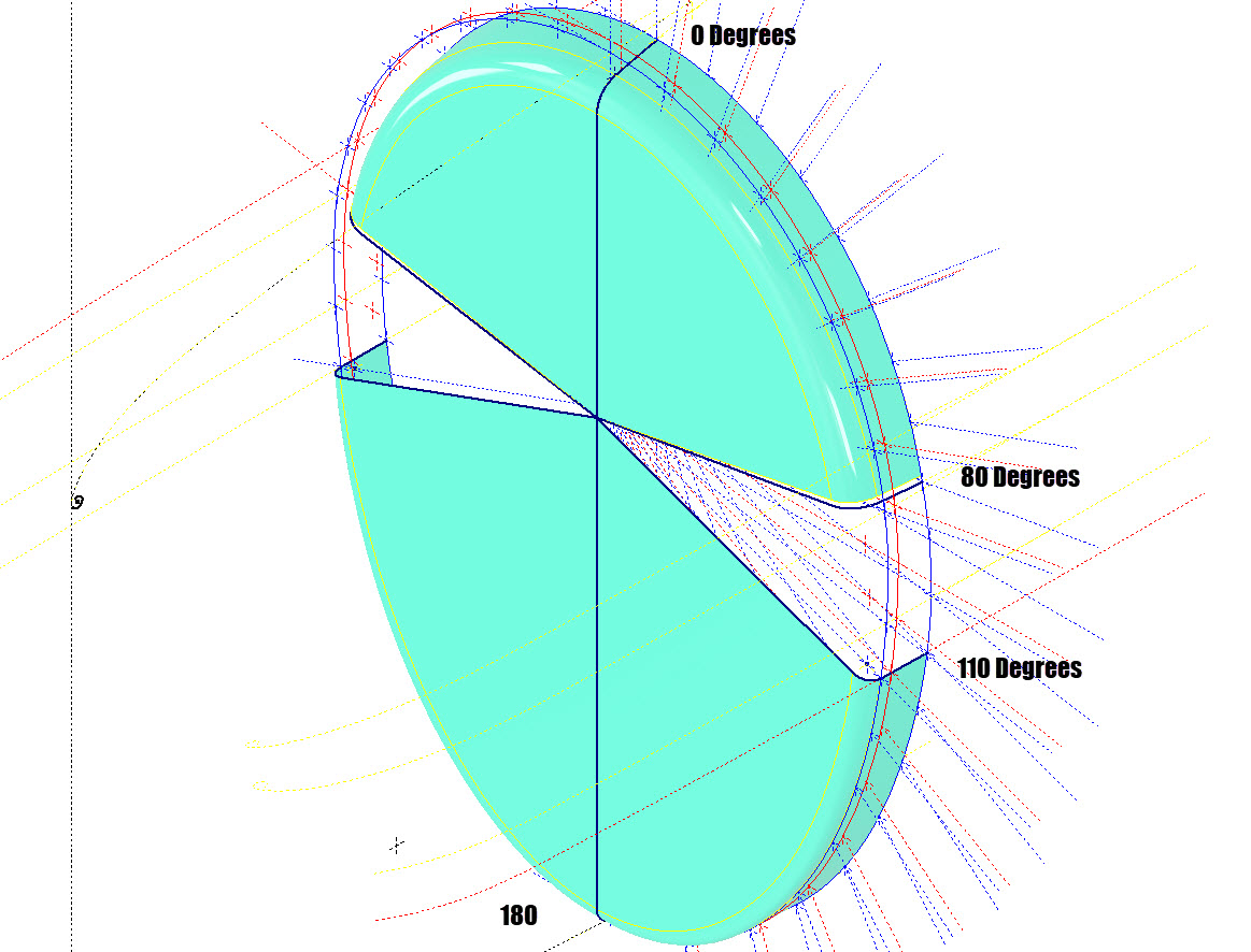
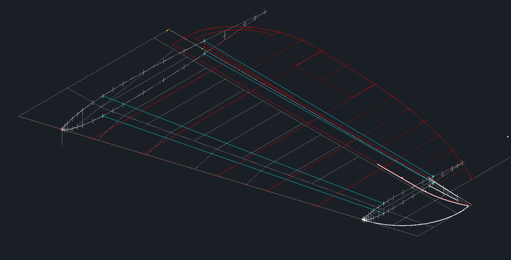
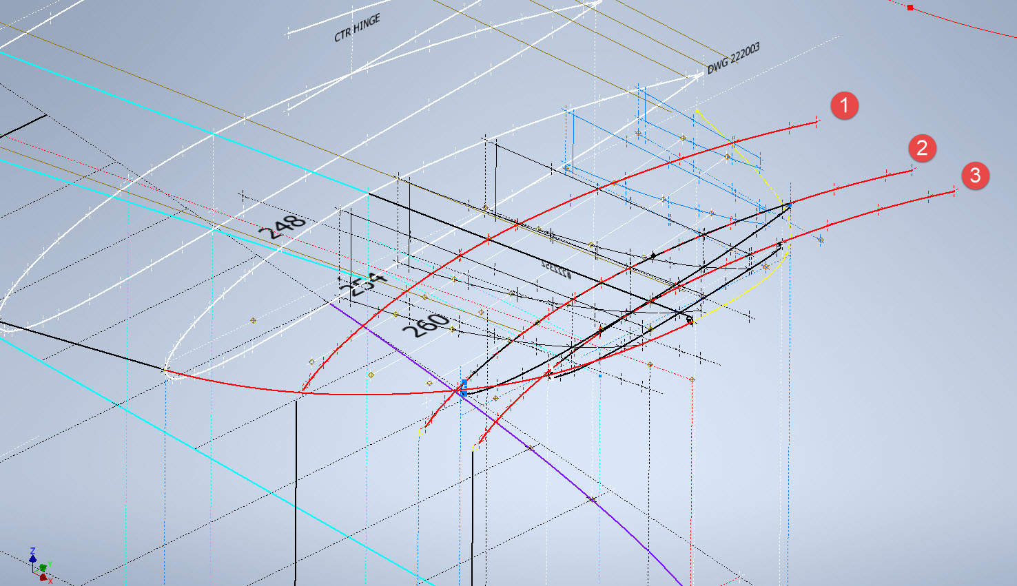
In each case, you’ll notice that these profiles are not closed. The base lines shown in the front view are defined as construction lines, and the end curves in the plan view are also intentional. This design choice allows the main profile lines to be used later for creating a Loft and for selecting a 3D Sketch Intersection. The center line of the arc in the front view will serve as the second selection for this 3D sketch. Additionally, note that the curves in the plan view are elliptical.

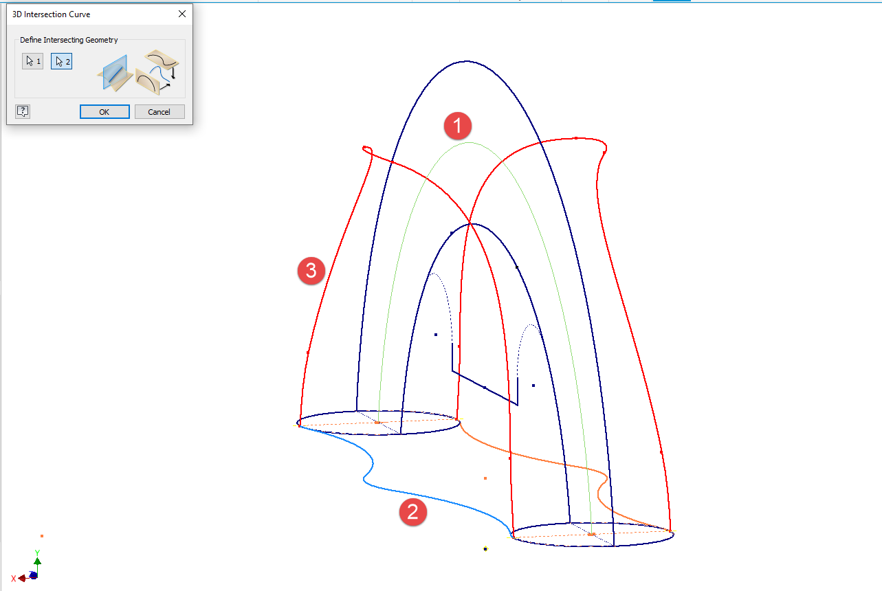
The purpose of the 3D Intersection sketch is to define guidelines for the eventual loft. Using the 3D sketch feature, we first select the center line from the front view and one curved edge from the plan view sketch. The resulting intersection will serve as the 3D path for the loft. This process needs to be repeated for both sides of the handle. The ellipses that will form the ends of the loft are created in a separate sketch from the previously mentioned plan view. This keeps them as distinct entities.

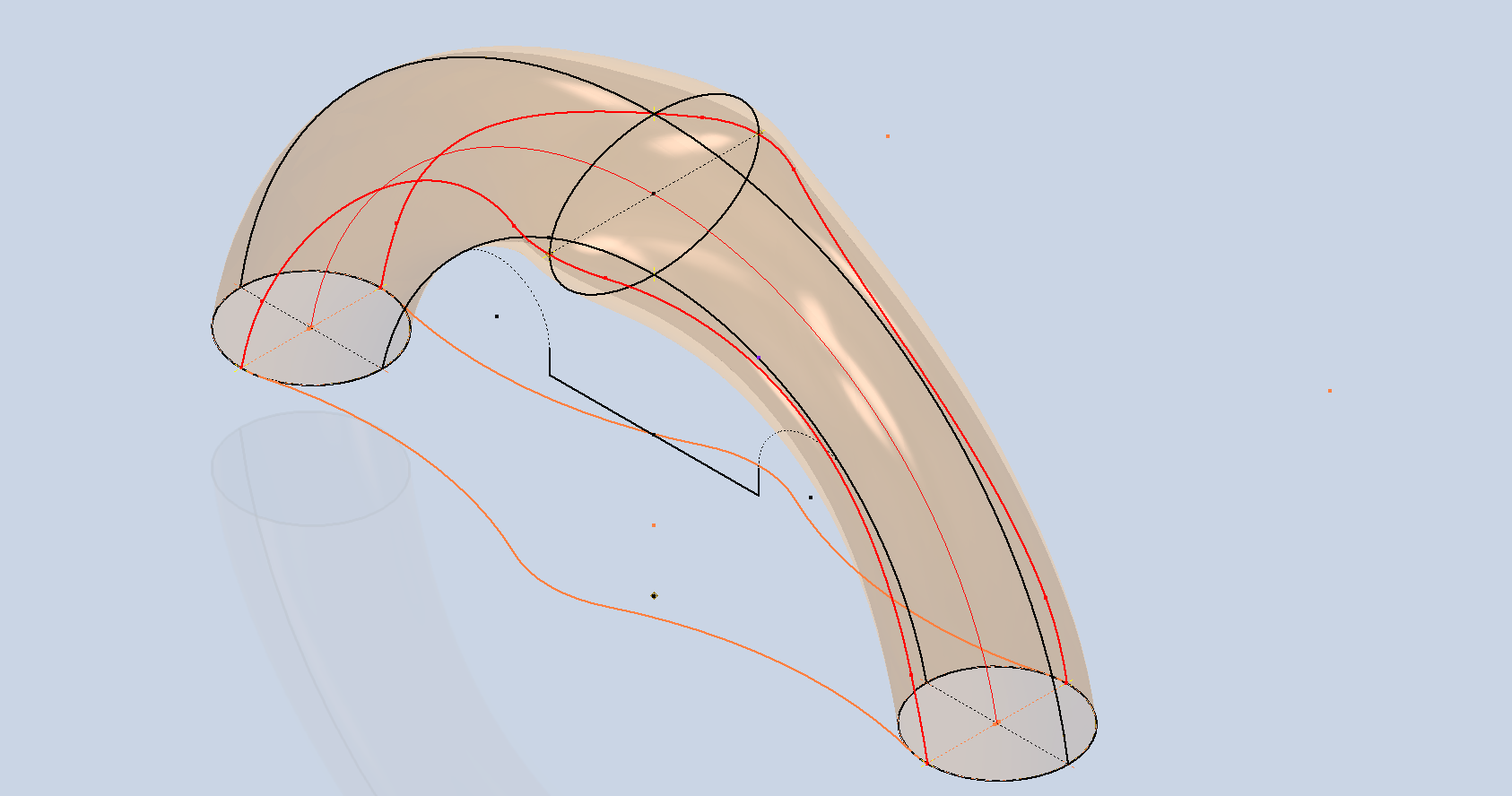
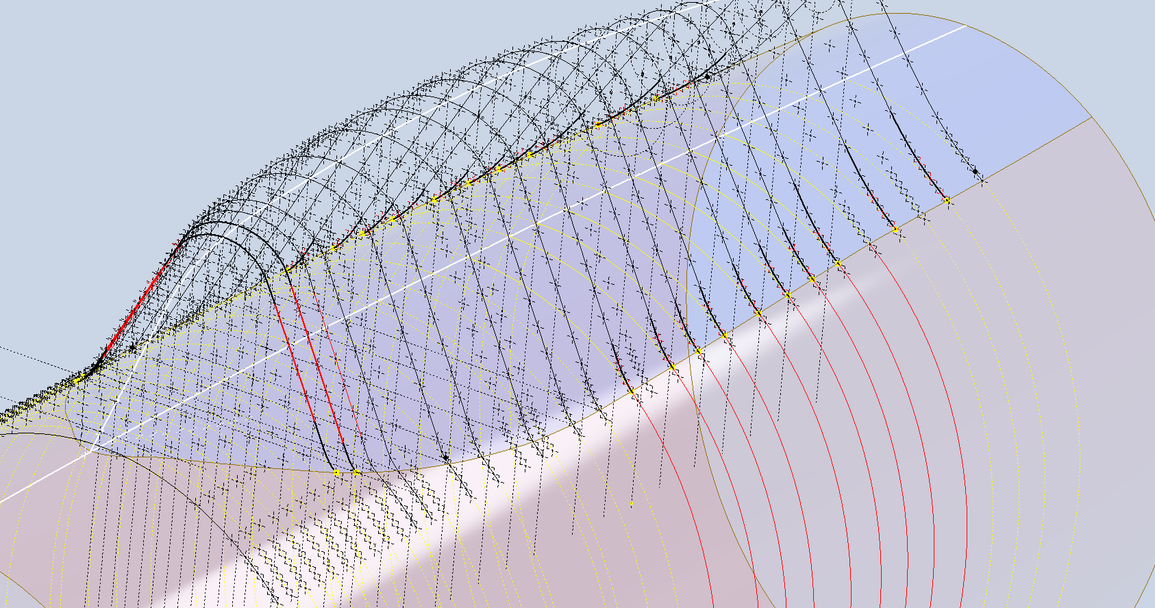
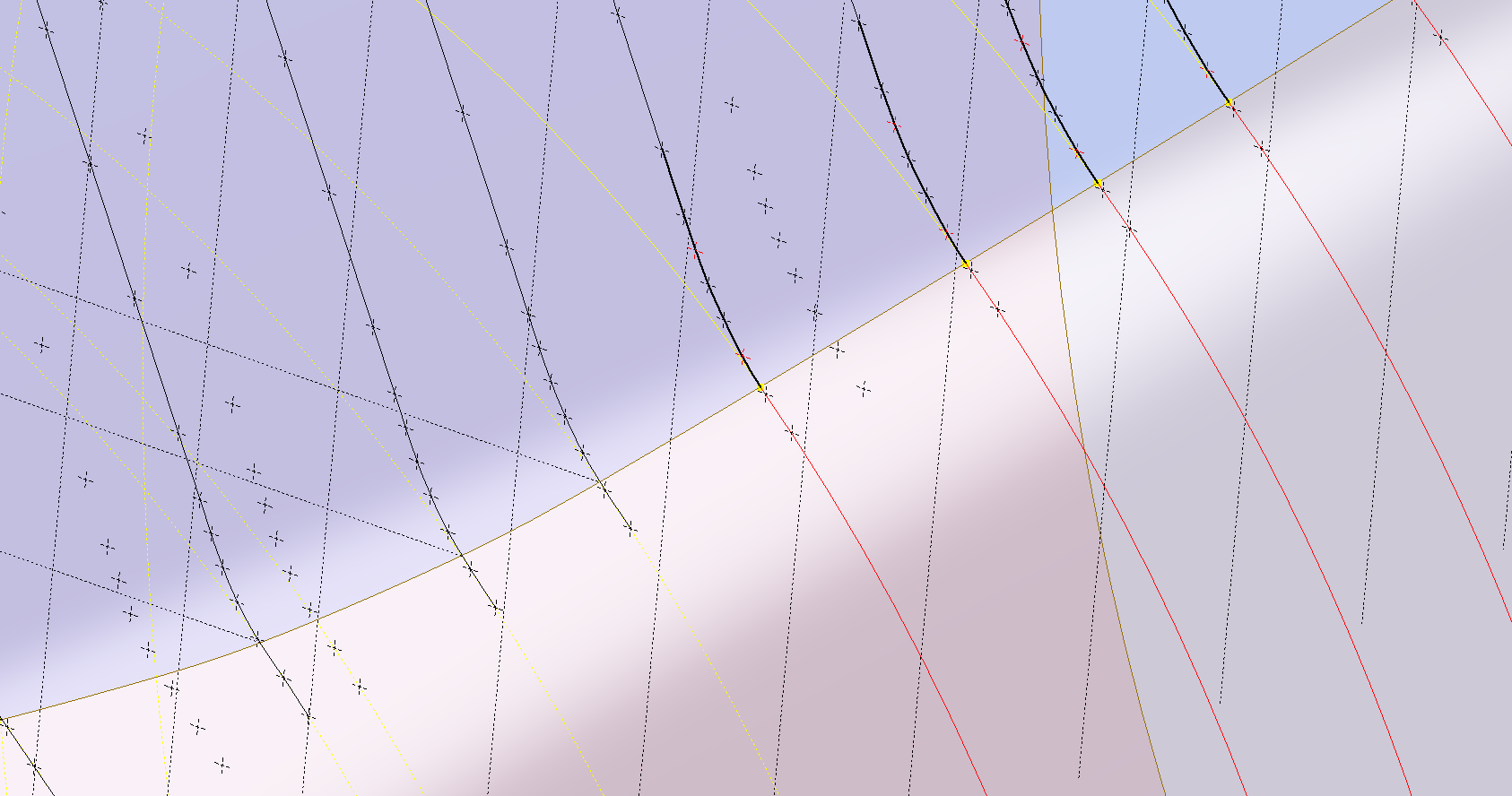
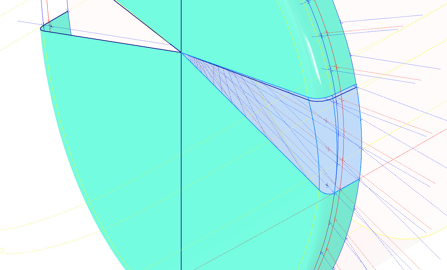
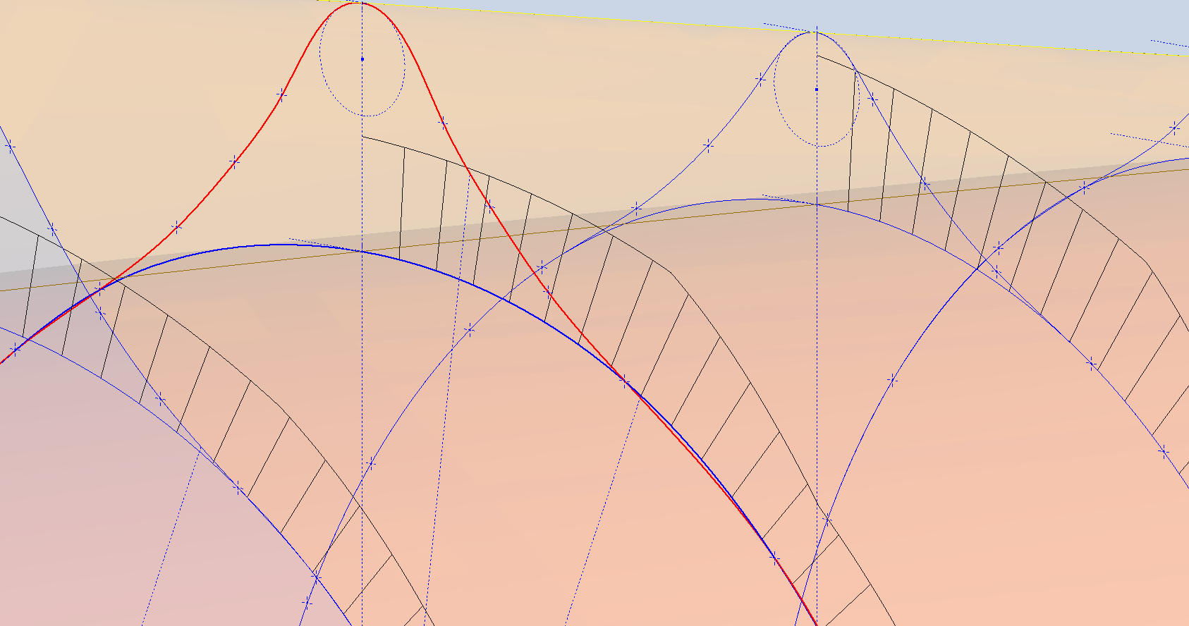
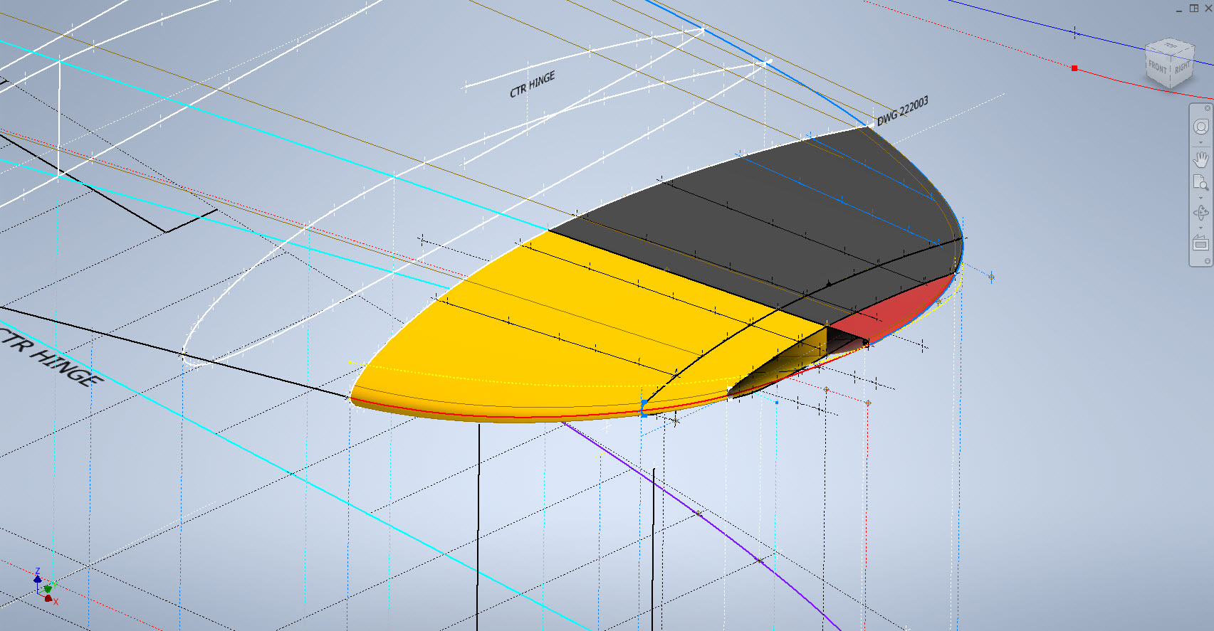
Hold on a moment; where did the ellipse in the middle of the arch come from? If we simply loft the two end profiles of the arch, as shown earlier, we can create an acceptable model, but it won’t be ideal. In the second image, where both surfaces are overlaid, you can see that this approach tends to create a diamond-like cross-section in the center. While this is not entirely incorrect, incorporating the ellipse in the center of the arch results in a much better finished surface, ensuring good continuity, as demonstrated.

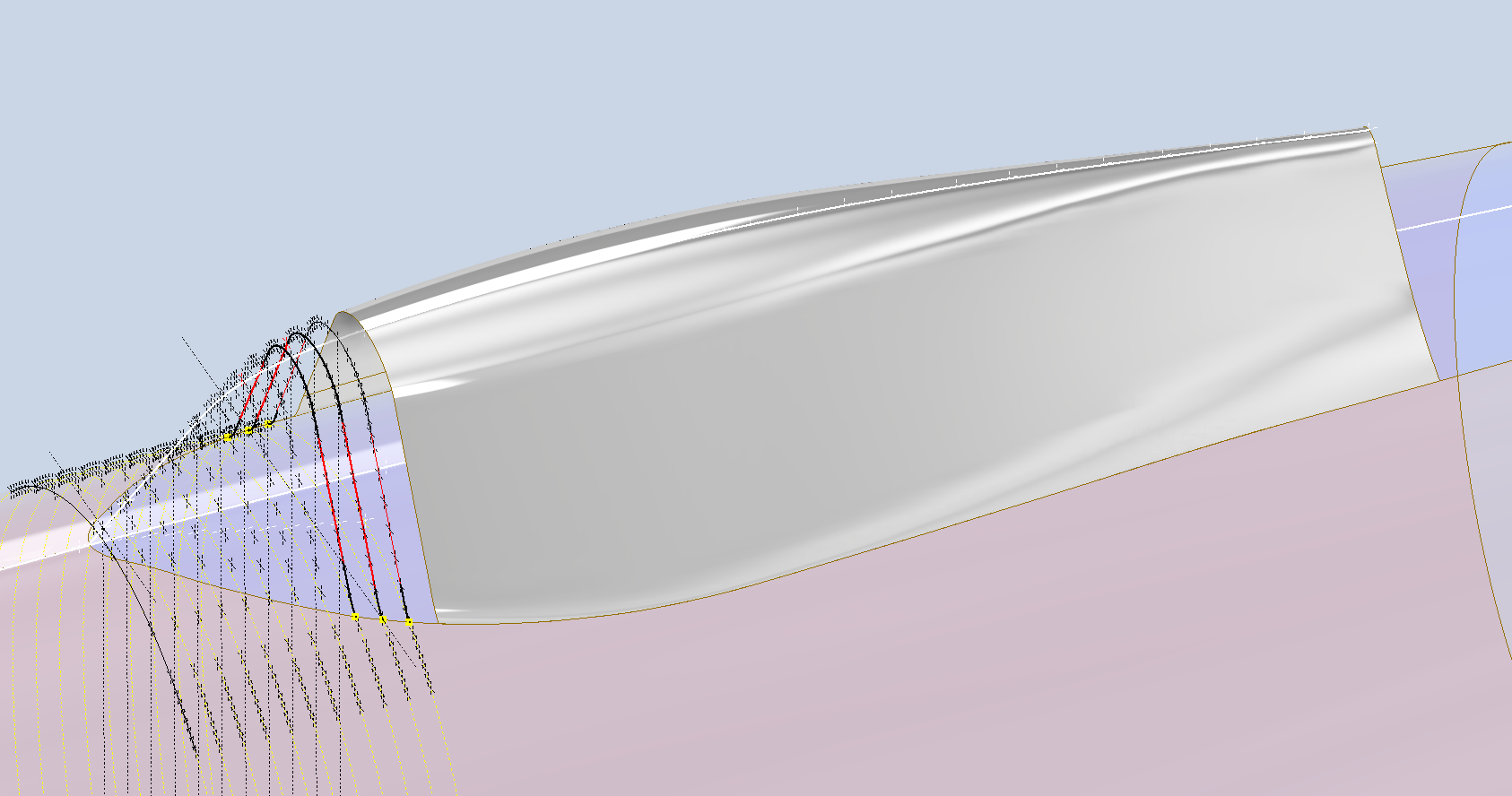
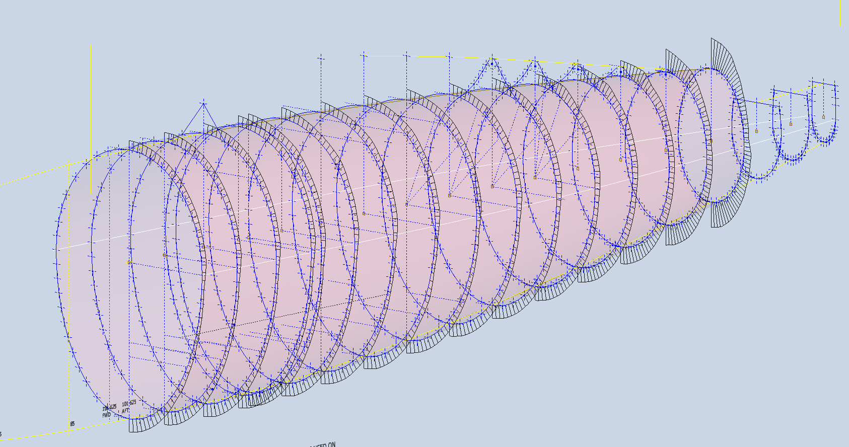
Once we have the arch lofted surface, we extrude the centre section circle to match the surface contours.

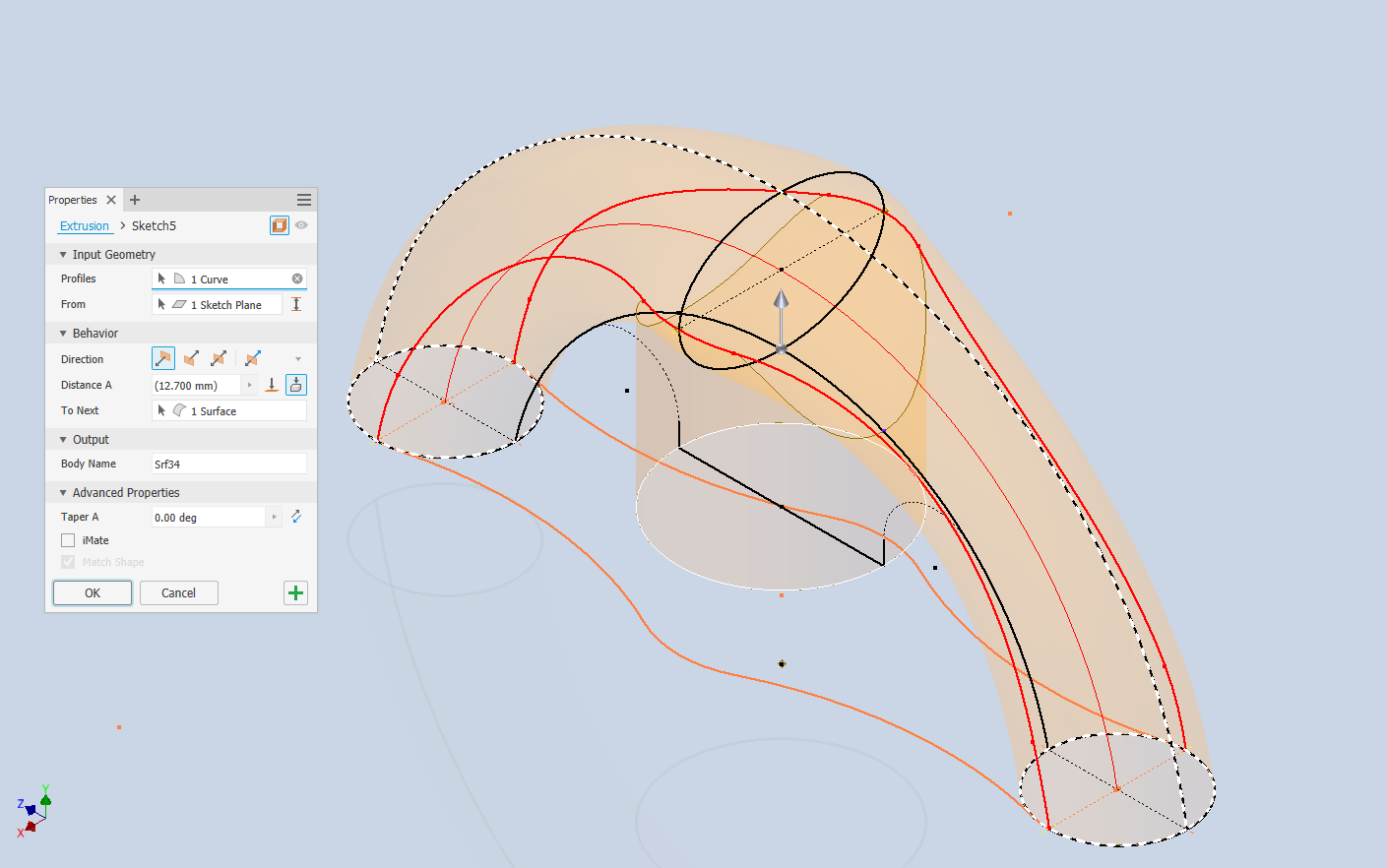
We then use this extrusion to trim the underside of the arch surface, apply patch surfaces to fill in the ends of the arch and this centre section. Then stitch everything together and we have the main solid model.

Apply a fillet as shown to the underside; note the fillet in this case is better selected as a tangent fillet and not a G2 curvature. It is often tempting to overuse the G2 fillet option as the perceived notion is that it creates a smoother finish, which by the way is correct, though in a case like this it tends to sharpen the fillet corners which is not good. Something to watch out for when applying fillets.

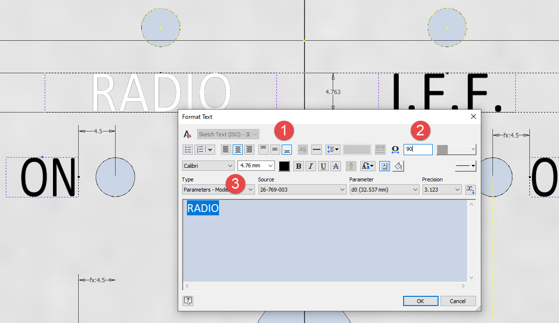
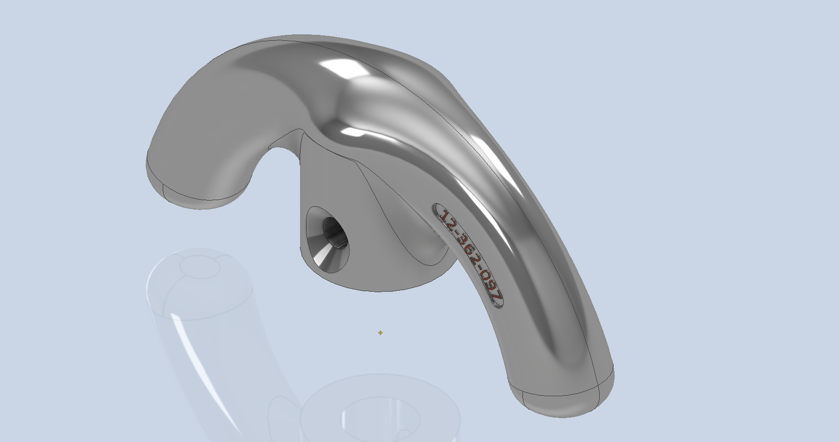
To finish up we add the holes as specified, fillet the ends of the arch (a good opportunity for a G2 fillet) and add the part identifier. The final part should look something like this:

In summary, when developing surface models, it’s beneficial to explore your options and start by creating sketches that support your plan of action. Consider using 3D intersections to define loft paths, and incorporate additional geometry as needed to maintain the circularity and continuity of the final surface.

This part is ready for manufacturing, which will probably be 3D printed for this static display restoration.

Typical Design Workflow:

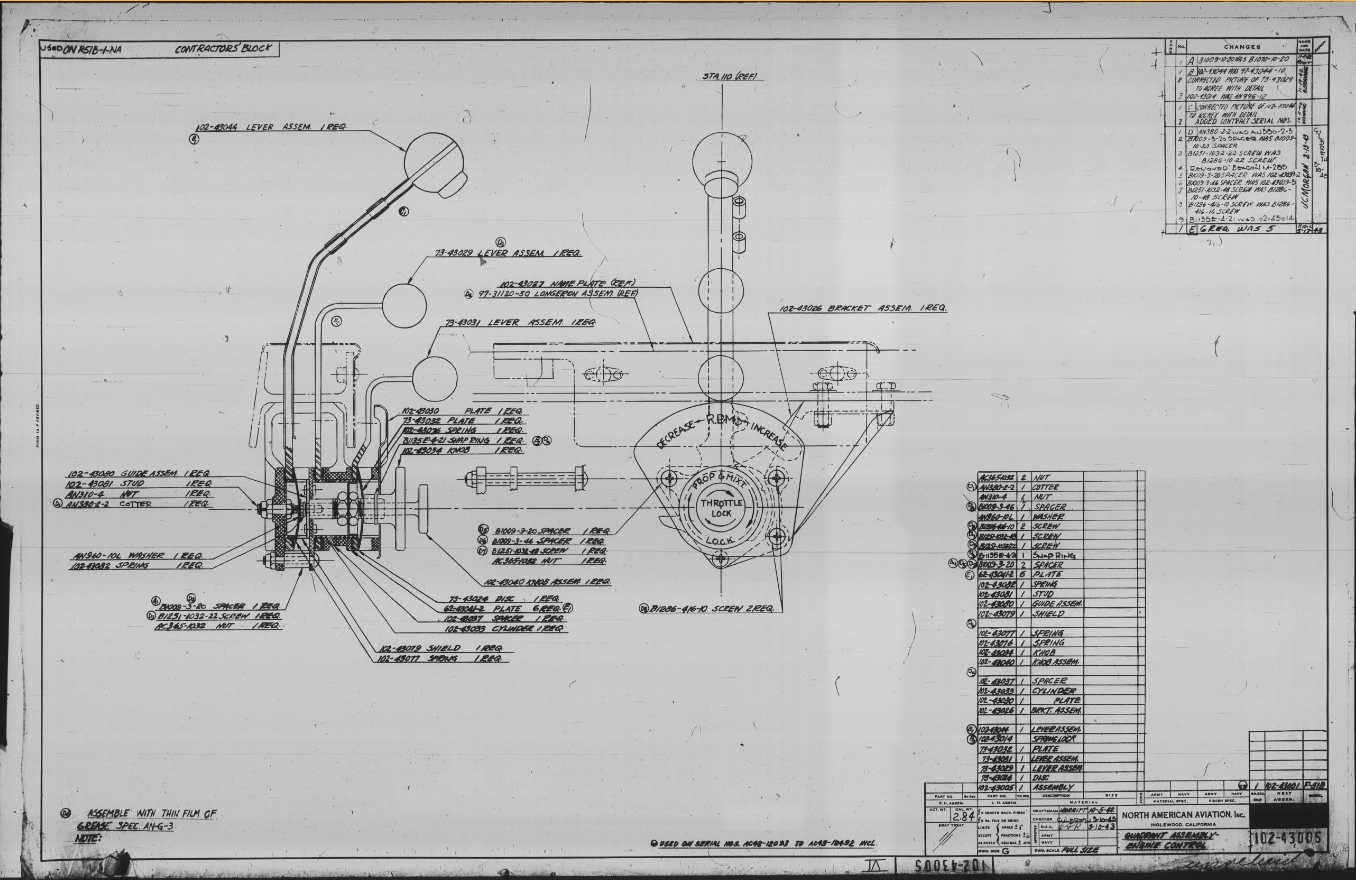
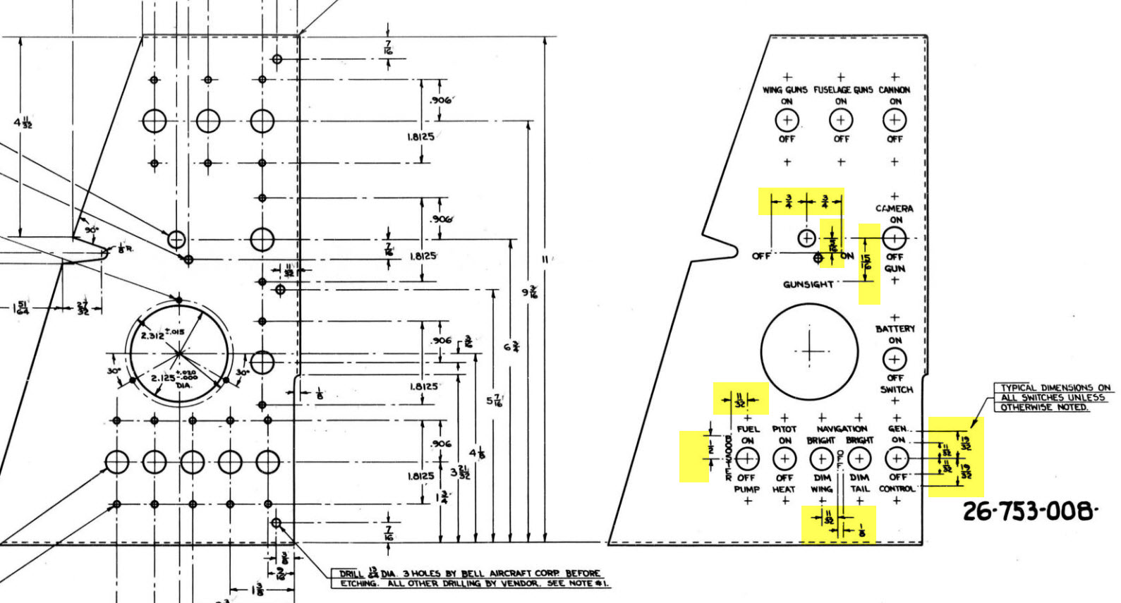
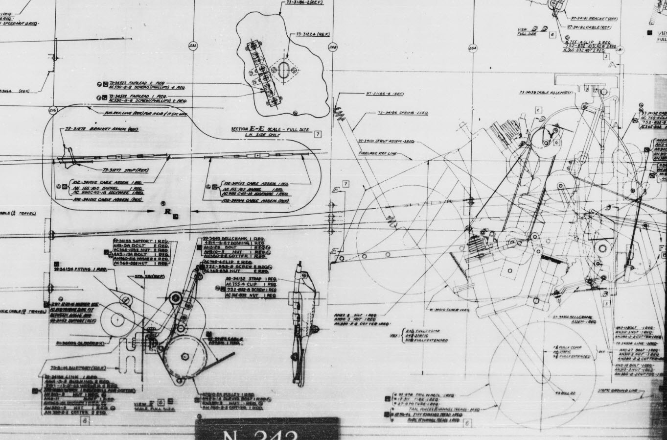
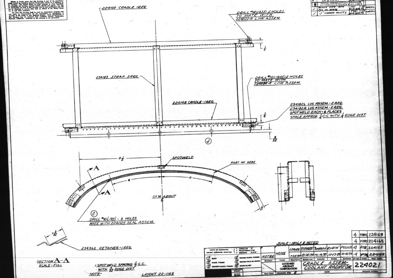
Usually I would initially receive an inquiry via email from companies like Planes of Fame for a 3D CAD model of a specific part or assembly. Typically, the request includes a brief description of what is needed and not necessarily the actual part number. In this instance, it was for “the handle for operating the window glass.” I then searched through my archives to locate this item, reviewed the part’s blueprint, and checked which parts or assemblies it connects to ensure I have all the relevant information.

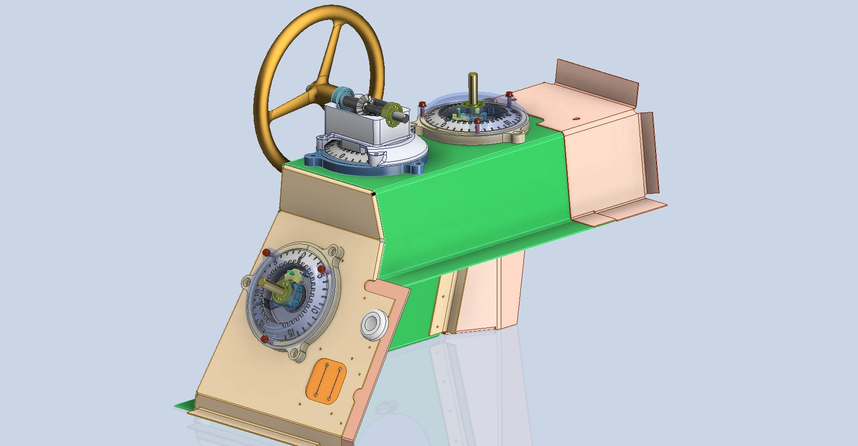
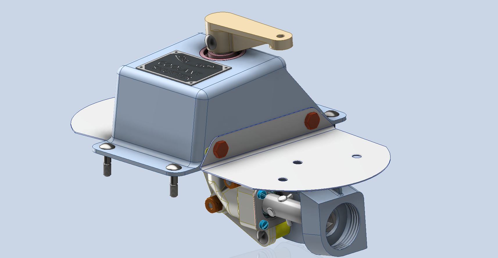
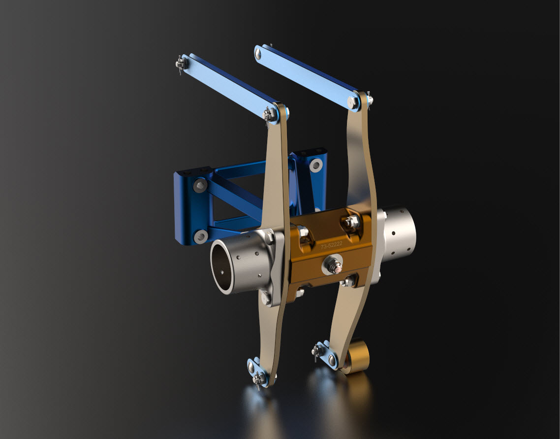
I will make every effort to start working on the CAD model as soon as possible, regardless of the time of day, to minimize any delays. For example, I received an inquiry about a part at 9:17 PM last night for the “P-39 Throttle Control Mount.” Following the established procedure, I was able to begin working on it relatively quickly on a Friday evening. The finished part (#12-631-027) was completed and submitted on Saturday at 11:17 AM. The final design included both the original 3D CAD model and a fully dimensioned 2D drawing, which is essential for verifying that all dimensions conform to the original blueprint.

This part will likely be 3D printed for the restoration of the static display, so the 2D drawing serves both as a dimensional check and a reference for manufacturing. If the inquiry had required a metal casting manufacturing process, the drawing would include more detailed information about part machining and the tolerances necessary for a full-metal manufactured item.

If you’re looking to bring your ideas to life with accurate 3D and 2D CAD models for replica parts, I would love to help! Don’t hesitate to get in touch hughtechnotes@gmail.com

Technote: P-47 Canopy Contour Lines

Technote: P-47 Canopy Contour Lines:

In a previous post, I discussed a minor discrepancy at the intersection of the canopy contour lines and the fuselage contours. This discrepancy is quite small, measuring around 0.3 mm, which is generally considered an acceptable tolerance. The purpose of these CAD/Ordinate studies is to provide the most accurate dimensional record for the various aircraft currently available, so it is crucial to ensure that these measurements are correct. However we must first understand design intent and check that the canopy contour ordinates are designed to match the fuselage contours.

Depending on the aircraft manufacturer, the canopy contour lines may not align exactly with the fuselage because the canopy surface is typically offset from the fuselage surface, which is reflected in the information provided. For the P-47 you can see the ordinate points are an exact match with coincident curves from the fuselage surface therefore the tangent line is actually defined by the intersection between the canopy contours and the fuselage contours.

Initially, when I started this study, I profiled all the ordinate points for the canopy and compared this with the fuselage surface, revealing a minor discrepancy. The thing is we don’t have to fully connect all the coordinate points for the canopy, just the points above the intersection line.

First, we need to define the actual definition of this intersection on the fuselage surface which will be transposed to the canopy model. We take the vertical dimensions from the fuselage centre as defined on the canopy ordinate drawing #89F11456 and create a sketch which will be lofted to split the fuselage surface. On the second image above you will notice a number of prominent points on the upper curve profiles. These ordinates are not shown on the early P-47D drawing but are shown the on the later P-47D and P-47N ordinate layouts.

Initially, I opted for a tangent spline curve to complete the main circular profile of the fuselage bulkheads as per the ordinate drawing thinking that the relevance to the finished profile was nonessential. However when I compared the first run of the canopy and fuselage alignment studies I found that it was necessary to include those additional ordinates which are now included in the spreadsheet record.

These images show I have opted to correct the minor discrepancy by only profiling the canopy to the actual intersection line. I should note the Canopy and Fuselage are separate CAD models which means I can derive the surface from the fuselage model and manipulate it as required in the canopy model without affecting the original. For each canopy station, I projected a section thru the fuselage surface which gave me a spline to which I could add a tangent constraint when profiling the canopy lines. The images show the initial interpretation of the canopy profiles and the corrected profile in red (construction geometry omitted for clarity).

Tech Tip: if we had instead derived the station sketches from the fuselage model and then projected this in the canopy frame sketches as an outline we would not be able to add a tangent constraint. This is a limitation with Autodesk Inventor when working with splines and the workaround is to project a surface cut section as I have done above.

For each canopy station, I am only sketching the ordinates down to the intersection line with the fuselage and adding a tangent constraint to the projected fuselage profile curve. Because we split the fuselage surface we will have a point at the split that we can use in the profiling of the canopy frames.

The actual skirt for the canopy obviously overlaps the fuselage surface and therefore we will have to define the edge relative to the tangent intersection line. As mentioned before we can manipulate the fuselage surface that is derived in the canopy model which means we can trim that to suit without impacting the fuselage model.

The tricky bit is ensuring that the edge of the skirt is exactly the same dimension from any point along the intersection line and this is how I do that.

The first thing to do is create a work plane perpendicular to the intersection line and draw in a partial curve and then sweep this along the intersection line path. The reason for this being a partial curve and not a full circle is because there is a tight radius at the front edge of the canopy which may not be possible to traverse using the sweep command if this was full circle.

When this is done it is a simple exercise to trim the derived fuselage surface to obtain the skirt surface.

By creating a curved sketch and sweeping along a curved profile we ensure that at any point along this path, the distance to the resulting edge is exactly the same. A similar technique will be employed to develop the finished edge of the glass panel models.

I still have some work to do on the windscreen portion of the front canopy and then I will fully model the structural components.

Technote: P-47 Cowl Ordinates

Technote: P-47 Cowl Ordinates:

The Ordinates for the P-47 Cowl are listed on Republic Drawing #89P63300 for P-47B, C and D. They differ from the usual ordinate dimensions that usually comprise X and Y coordinates in that they are radial ordinates. Essentially dimensions along a radial axis that are subdivided in 10-degree increments from 0 degrees to 180 degrees.

The ordinates as usual are extrapolated to a spreadsheets where I have also converted the radial ordinates into X,Y coordinates should this be required. The highlighted dimensions are the points on the inside face of the cowl skin. The dimensions at Stations 70 and 71, bordered in red, are to the centre of the secondary cowl leading edge radius at each degree increment. To be precise this is actually the profile for the Preheater.

The edge radius at the top of the Preheater is 2 7/16″ at Station 71 and 1 7/16″ at Station 70. On the Republic blueprint the radius of 2 7/16″ is applicable from 0 degrees to 100 degrees, and the radius of 1 7/16 ” is applicable from 110 degrees to 180 degrees. In the CAD drawing above, I have noted 79-degree and 110-degree intervals, and there is a reason for this.

At some point along this Preheater front edge, there is a transition from the 2 7/16″ radius to the 1 7/16″ radius. The republic blueprint for Preheater #89P621101 details the profile section that is applicable at 90 and 100 degrees showing the top radius at 2 7/16″ however it also notes an option where the radius fairs from 79 degrees to 110 degrees instead of 100 degrees to 110 degrees.

Personally, I prefer the latter as it ensures a smoother surface continuity. As you can see in the following image of a recent P-47 restoration they appear to have opted for the former which displays a noticeable bump from the 100 to 110-degree transition. The second image is the CAD interpretation of 79 to 110 degrees which is much smoother.

I have modeled only the main portion of the Preheater body surface; there is a projected curved section forward of this which I will model separately and again a good reason for doing this*.

If we look at the CAD development of the Preheater surface model you can see I have developed the top profile with an ordinate radius of 2 7/16″ to the 80 degree increment and the lower section ordinate radius 1 7/16″ from 110 to 180-degree increment. However, when you loft the 2 profiles you can see the default curvature transition is not continuous…what we want is for the curved section to have smooth continuity throughout the transition.

I should note that the surface was developed to the 80-degree increment and then trimmed back to 79 degrees; I already had the construction sketches in the model…just saves some work.

Inventor like other CAD software will attempt to interpret the desired surface loft but it does not always achieve the desired result. This is easily corrected by selecting transition points within the Loft dialog which will enable a smoother transition.

Going back to my earlier comment on the projected curved section*; as per comments above; the CAD-interpreted surface may not produce the desired result with more complex geometry. So often the best way of doing this is to model that section separately ensuring finer control over the finished surface.

CAD Tip: The vertical face of this developed surface is flat, occasionally when lofting, sweeps or even applying a surface patch it is always a good idea to check the finished surface is actually flat and planar where expected. The way to check that a surface is planar is to select the New Sketch option using the surface as a sketch plane…if the surface is planar it will allow a sketch.

P-47 Engine Mount:

On the Republic Drawing #89P62101 for the Engine Mount the intersection point of the top diagonal brace with the centre of the front ring is not clear.

On the Front View, we have either a dimension of 8.75″ (1) or an Angle of 58.5 degrees (2). To verify which is the correct set out for the top brace we turn to the elevation view. Here we have a cross brace intersecting the top diagonal at 20 21/32″ (4) and 16.592″ (3). Drawing in this intersection point in conjunction with the known datum at the extreme right we project the centre line of the brace to intersect with the front ring.

This projected point is within 0.017837600 mm of the point determined by the dimension 8.75″ (1) and 1.057782238 mm where the angled line (2) intersects with the ring centre. This verifies that the actual point of intersection is the dimension 8.75″.

P-47 Fuselage Curvature Analysis:

The following image shows the curvature analysis at each station of the fuselage. Only 4 rogue points were micro-adjusted to align correctly. What we are looking for here is not perfection but consistency. You will notice a small flattening of the side curves around the centre of the fuselage, which is fairly consistent throughout. The primary reason for doing this is to identify any points that will create a negative curvature or completely in the wrong position.

The next challenge is to identify the correct tangent points between the humped back ridge curves and the main fuselage. It may tempting to just profile a spline connecting all the points from the ridge curves and the main fuselage but this is likely to create small imperfections where the tight curves meet the main body profiles…so it is always best to do this separately.

In the first image above the red line is the best fit spline connecting all profile points and you can see how it dips below the curved profile from the blue main fuselage curve profile. From the Republic ordinate drawing it is clear the intent is for the ridge profile to be tangent at the point of intersection.

The finished profiles will look something like this…

P-47 Ordinate Study Update

P-47 Ordinate Study Update

For most of this year, my primary focus has been the restoration project for the P-39 at Planes of Fame. That is still very much work in progress. At this stage, it is mainly the fabrication side of things, as the majority of controls have been drawn. The mounts for the Gunsight are currently being made. I hope to include some photographs of the installation in a later post.

The Gunsight was an extensive and challenging study…the drawing layout shown above was derived from a dozen or so blueprints and various manuals compiled together on one drawing. The circled dimensions are those verified from one or more sources.

During this time I have been doing some preliminary studies for the P-47. Over the last few weeks, the P-39 project demanded less of my time which has enabled me to further develop the ordinate study for the P-47.

The basic Layouts are developed for the Cowl, Fuselage, Empennage, Wings and Cockpit Enclosure. Still a lot of work to do on the details and resolve a number of queries.

One particular area of interest is the wings. As you can see a lot of work has been done on this layout which shows the Main Spars (shaded), Flaps and the leading and trailing edge profiles. The Aileron and Wing Tip is still a work in progress. The wing comprises 6 thickness variations of the S3 profile…15% at Sta 0 (Ctr aircraft), 14.2% at STA 74 (0.3 x Span), 12.3% at STA 123 (0.5 x Span), 10.5% at STA 172 (0.7 x Span), 9.2% at STA 222 (0.9 x Span) and 9.0% at Tip extent STA 246.

For the Main Spars we have the vertical dimensions coupled with the correct lines for the Flaps and Leading edge providing key important ordinate points that the rib airfoil profile should match. For the Airfoil ordinates I referenced documentation on the Republic S3 profile from the UIUC website and The NACA Technical Reports WRL-98 and WRL-159.

For The Horizontal Stabiliser we do have good information to develop a 2d plan layout including the dimensions for the Elevator to derive an accurate trailing edge. We lack sufficient depth information for any of the spars or ribs. Therefore, it is important to ensure we have the correct Stabiliser airfoil profiles.

The Republic blueprints list the airfoil ordinates at station 10.5 and station 83. These were recorded on spreadsheets and subsequently onto the CAD model. I found that the alignment for the spar positions and the 70% chord were slightly out. I reverse engineered the offset ordinate data to derive a Basic profile which I intend to use to further develop the intermediate ribs.

The first table above shows the recorded ordinate data for the airfoils at Sta 10.5 and 83. Working back from the offsets you can see the Basic Ordinates are similar but not exact. Therefore it seems logical to take the mean values from both tables to derive a workable basic profile which I can use later, shown in the middle column. The second table shows the adjusted ordinates for each profile. You may be asking what recognizable profile did Republic use for the stabilizer…again I do not know for sure. I have a parametric table setup for the more common NACA profiles used for other similar aircraft and none match.

The key dimensions for the profile relate to the 70% chord offset and the alignment with the front spar center. What I think is happening is the area from the leading edge to the 70% chord defines the surface for the Horizontal stabilizer and the curved trailing edge of the Elevator is essentially morphed to this line. What few vertical dimensions we have from several areas tend to match with this arrangement.

The cyan lines show the alignments at the front spar and the 70% chord for reference. The plan outline for the Elevator is drawn according to the known ordinate points. The second table above is designed to give me the airfoil offsets for any rib according to the chords derived from the CAD model…this is essentially the position of the measured 70% chord and is calculated to give me the actual chord length. All of this will be verified which means trawling through the many thousands of blueprints I have to find key offset data I can check against. Of course, I could use the Aircorps database for this but the many scans of this area are blacked out..the archive I have is much better quality.

I take nothing for granted with these studies and try to verify dimensional information from more than one source. I firmly believe that if we get the dimensional information correct everything else will fall into place.

As usual please get in touch with any technical queries or comments. hughtechnotes@gmail.com

Update 20th Dec 2024:

I have the basic geometry for the Horizontal Stabilizer and Elevator worked out…some detailed work is yet to be done on the Tip and the main Spars.

Technote: Inner Workings

Technote: Inner Workings:

Working on the controls and instruments for the P-39 spawned a plethora of questions about how these controls actually worked. So I endeavored to incorporate the inner workings in the Trim Tab Control CAD models. This was specifically to get a better understanding of how they work. This was not a mandated requirement. The initial work scope was replicating the external components for a static display P-39 restoration.

Often enough in museums and private collections, we only see the external controls. For many, this is all they want to see. But what if we also see the internal gears, pulleys, shafts, and bearings to understand how they operate? This is exactly where I now want to go with my future projects.

The Trim Tab controls for the Elevator, Rudder and Aileron are already modelled for the P-39 including the internal components. These dials and controls are currently being manufactured for the restoration project. The decision has now been made to incorporate the working mechanisms as functional replicas. This is great and will actually have some form of function, however, the mystery of operation still eludes the operator. I want to take this a step further and produce desktop models with Clearview casings so that the internals are visible. The exact method is still under review. It will mainly comprise 3D printing techniques for the main components attached to perspex casings.

The dials for all 3 controls are similar with the Rudder and Aileron dials operated by a control knob (not shown) and the Elevator Tab controlled by a wheel as shown. At the base of each control dial there is a sprocket for a short Roller Chain which in turn is attached to operating cables. Out of curiosity I decided to have a look at other aircraft to see how alternative mechanisms were developed for the P-51 and the FM2.

For the P-51 the Trim tab controls are comparable in their operation with the internal gearing arrangements but differ slightly in design.

The dials for the Aileron, Elevator and Rudder are all similar to the CAD model shown. The Elevator and Rudder have cable drums attached to a long shaft for direct cable operation whilst the Aileron has a chain sprocket similar to the P-39 Trim Tab controls.

The plan for the P-51 is to fully model all the components in the assembly shown, complete with cables and chains to simulate operation.

A small point of interest; the various aircraft designed by the same manufacturer often share common parts; for example the NAA drawings for the B-25 share the same Trim Tab control knobs as the P-51 and listed accordingly. For some reason, the P-51 drawings do not reciprocate.

If you can’t find drawings for a particular part, check collections for other aircraft by the same manufacturer. Occasionally, this can be worthwhile. Similarly, with Grumman, many parts were shared with the FM2 and the Grumman Goose.

The above model is the FM2 Elevator Trim tab control, the main body of which is typical for the Aileron and Rudder on Grumman drawing 13690. The Grumman Goose has similar controls shown on the Grumman Drawing 13693. Shared components across the various aircraft are listed on the Grumman FM2 drawings.

This Trim Tab control for the FM2 is probably the most complex I have studied so far…requiring very fine manufacturing tolerances. I am not entirely sure yet how this works as there is a complex array of tabbed washers that act as stops for the dial in both directions; it is unclear at this stage how they should be configured…I will get it worked out in due course.

A lot of work to do on these projects which will definitely keep me busy through 2025.

Technote: P-51 and P-39 Standards

Technote: P-51 and P-39 Standards

During the development cycle of any aircraft the manufacturing standards tend to evolve and commonly change content, description and name. Keeping track of those changes is key to ensuring the defined parts are correct for the assembly of components.

Alongside the P-39 Restoration project, I still develop several aircraft components for other aircraft. This includes my old favourite, the P-51 Mustang. This example refers to the Quadrant Assembly for Engine Control; drawing #102-43005 for the early P-51B.

Many of the standard parts called up on this assembly use the early standard references. These are typically prefixed with “B”, like B1009, B1135, etc. These standards were later updated, and a new series of standards replaced them. I have correlated these in a spreadsheet, as shown below.

The spreadsheet only lists the standards that are available in the blueprint archive and may not be a complete record. For a more comprehensive listing, refer to the Erection and Maintenance instructions for the P-51A series (T.O. No. 01-60JC-2). Check the Conversion lists from pages 404 onward.

The CAD development of the Quadrant Engine Control is still a work in progress…created to the exact original dimensions.

My plan for the P-51 is to further develop the instrumentation for the early and later versions.

P-39 Update and Standards:

Over the last few months, the P-39N Restoration project has been my primary focus. We are close to completing the CAD work for the Cockpit instrumentation.

By contrast to the P-51 Mustang, we don’t have the same collection of Bell Standard part blueprints. We only have what is available within the manuals. However, the notations for the parts are similar for the industry as a whole. For example, a Spacer Part noted as Q065-6-20 shares the same notation for the dash numbers as the P-51 (standards 4s3 and 4S4). This in turn will define the spacer size…the first dash number sequence indicates the bolt size and the second is the length. In this case, it would be #6 bolt size. The length is defined in 1/32nd inch, making it 20/32″ (5/8″) long. This table derived from the iPart feature explains the designations in more detail.

The next time you come across a part reference you are unsure about, cross-reference it with other aircraft-known standards. Also, consult the comprehensive collection of AN and MS standards on Everyspec.com.

Technote: Rivets

Technote: Rivets:

Developing the CAD standards for Rivets has been on my to-do list for far too long..so with the progression of the P-39 cockpit instruments it has become a priority. Typically on the Bell drawings and other aircraft manufacturers’ drawings we may only have the hole sizes noted, the rivet designation or information pertaining to the same but unreadable. Also occasionally even when we do have the hole sizes and the rivet designation often we don’t have the length required.

Something needed to be done to make this task a lot easier, particularly when you have instrument panels that incorporate many different types and sizes of rivets.

The first part of the process is to create several parts for the various types of rivets; which at the moment are listing the most common sizes I need right now. You will notice that the Rivet Name does not include the material type as doing so would require an extraordinarily large table of data. So the name is simplified to make this task easier to correlate but also because the priority at this time is dimensional correctness for rivet type, diameter, hole sizes and rivet length. At some stage, I will invest some time into deriving the various information sources to correctly name the rivets according to the AN and MS standards.

To complement the CAD iParts I also have a few spreadsheets listing key parameters and fabrication criteria.

The above tables are self-explanatory with the inclusion of a designation for a Bell Standard Rivet 35R1. I have actually found dimensional information for this type which I will include in the CAD library. This is where things get interesting because of the scarcity of historical components that may no longer be available, it may be necessary to find suitable alternatives.

You will notice that the Rivet Grip tables are in inches and mm…as I tend to work using metric mm templates (although the dimensions are input as inches) it makes it easier to measure the material thicknesses in mm and determine from that the rivet length. There is a technote somewhere on my blog that describes the process of inputting inch dimensions in metric mm templated models.

This will be an invaluable asset moving forward with the cockpit rebuild on the P-39. For example where there are issues with the legibility of key information on the Bell assembly drawings I can refer to other connecting part drawings that may only have hole diameters but will be sufficient to determine the correct rivet type and size.

This is very much a work in progress and will be updated as needed.

Update: 28th August 2024:

I have updated the Rivet CAD files which now include AN426, AN430, AN442, AN470 and of course the Bell standard 35R1.

All Rivet CAD data files (iParts) are now included in the CAD Standard library (see CAD resource tab for further details) along with original spreadsheets of Rivet Grip and general details.

Technote: Accurate Label Placement

Technote: Accurate Label Placement:

For instrumentation Panels, the location and size of text is very important to ensure clarity. This is usually well documented on the manufacturer’s blueprints so it is essential we get this right. In Inventor for example and I am sure it is equally similar in the many different CAD programs the key is the Text justification…let me show you.

First of all a quick update on the P-39 Restoration progress. Much of the recent discussions revolved around fabrication and 3D printing. As mentioned in the previous article this restoration is a static display for which many of the parts will be 3D printed, although the key aluminium panels will still be fabricated as such. The very latest part to be issued for fabrication is this small Switch Box on the Radio Console.

A surprisingly complex box which will be 3D printed and the Nameplate will probably be CNC. The dimensions of the main box are not defined on the Bell drawings so I had to interpolate from the known information and other Bell references to determine the final dimensions. This took into account the clearance from the Drive Shaft connecting flange which is in very close proximity to this box. This also fits quite well into our discussion here on Label Text Placement.

Typically on the Bell drawings, for example, the panel drawings include the height and location of the Label text similar to the following.

The way we do this in Inventor is by using the Text justification feature in the text editing box.

In the first image, we adjust the justification using the icons at “1”. If the dimension to the text label is to the bottom of the text we set the vertical justification to the bottom and if the placement horizontally is to the centre we centre the justification. When you exit the Text editing box a Text outline box is shown in dotted (this is optional so make sure you switch that on). The appropriate edge of the dotted line frame automatically aligns with the justification of the text entities. This dotted outline can be dimensioned and constrained as you would any graphic sketch entity. The second image shows some examples of how the dimensions of this outline relate to the justification.

It is not unusual for the overall width of the label text to also be specified in which case the “Stretch” value can be adjusted accordingly, entity “2”. At “3” we set the font and height, make sure you have the text highlighted in all cases or these adjustments will not be applied.

Interesting to note that the text outline can be useful if you require a frame around your text. The dotted lines can be changed to normal sketch lines and extruded or embossed as required.

There are a lot of features in the text editing dialogue which I may do as a technote further down the line but for now, to get the label text in exactly the right locations this is the way to do it.

Technote: 3d Modeling to Clarify Assemblies

Technote: 3d Modeling to Clarify Assemblies

Interspersed throughout this blog are many examples of Technotes describing techniques and problem-solving primarily for 3d CAD modeling. Many of the part examples shown are actually created to address another major issue with Assemblies.

It is not uncommon for the assembly drawings to be either unclear or simply void of key information that would help establish relationships between sub-assemblies or parts. In many examples, it is simply that the reproduction of the microfilm prints is not sufficiently clear to comprehend what is going on, otherwise the omission of basic dimensional relationships.

For the P-51 Mustang, I fully developed the rear Landing Gear mechanisms to clarify what the heck was going on as the NAA Assembly drawings details were obscured.

It is too often the case that general assembly drawings tend to be nothing more than an illustrated parts list with few key dimensions that define locations or relationships between the individual parts. This is also true for many of the sub-assemblies. For the P-51 Tailwheel sub-assemblies, I also developed 2D detail drawings showing key dimensions and parts lists. Ideally, I would have developed presentation drawings showing the exploded views of each of these assemblies to provide further clarification…perhaps a project for the future.

In the case of the P-38 Lightning, I have developed the Landing Gear assemblies to check the ordinate dimensions… which by the way are good. I now have the Coolant Radiator assembly which was again developed to check ordinate data but also for the same reasons as I did the models for the P-51 Tailwheel.

Typically the general assembly pictorially shows the sub-assemblies without any key dimensional information to define the location or part relationships and similarly, the sub-assembly for the clamp is not that much better. This is important stuff as occasionally they are the only reference material we have to help define ordinate data that is missing from the archive blueprints.

The Coolant Radiator is compromised by wrong dimensions as well…the top clamp cover, for example, had dimensions for the connection to the rod with the part drawing showing conflicting locations for different views of the same part.

The problem here is the connecting bracket item 224045 cannot possibly be 1″ from the edge of the cover plate whilst the overall dimension of 6 7/16″ prevails. I initially had located that bracket at 1 inch which seemed to be correct at the time because it fitted the part profile but when I introduced this into the assembly drawing it would not correctly align with the radiator. However, when I revised this using the 6 7/16 inch dimension it worked. That connecting part also caused more problems because the face of the part is machined 1/64″ which is not taken into account when positioning the part in the assembly.

Accumulatively this resulted in the overall width of the clamp assembly being smaller than it should be. This only came to light when I modeled the 234183 almost inconspicuous part as the stated dimension of 9.25″ did not fit with my initial layout..my first thought was this may just be an oversight but when I tried to align the main support frame (in gray) it did not align correctly. I went through everything and realized that the machined face of the corner parts connecting to the rod as shown may not have been taken into account and when removed the alignment was better and the 9.25-inch dimension on the strap was now correct. I am convinced that there should be spacers/washers between those connecting parts but this is not apparent on the assembly drawings. There remains a small discrepancy of 0.8mm which I am unable to account for….as this mainly relates to a clamp mechanism that will be compressed on assembly it was probably not deemed important but when you are trying to establish baseline dimensions it is actually very important.

The Part catalogs generally are your first port of call when developing these assemblies but they do not contain the key dimensions you need so these 3d CAD models are essential to achieve clarity. Incidentally, while we are talking about part catalogs it is important to understand what parts belong to which version of the aircraft. For the P-38 Lightning, the first few pages list the version and serial numbers which in turn are listed elsewhere where a Usage code is assigned. In this case the “e” is essentially the P-38H and the “bv” is the P-38J. The P-38 Part catalogs tend to show the version variations on one page; which can be really daunting; whereas others may show the version differences on separate pages…so you have to be attentive.

As I mentioned at the beginning of this article the main purpose of these assembly models is to achieve clarity and to check dimensional relationships. I think this is very important stuff that would certainly benefit from exploded views in conjunction with clear assembly 2d drawings.

As usual, get in touch if you can help support my work. hughtechnotes@gmail.com

Technote: P-38 Lightning Wing Tip

Technote: P-38 Lightning Wing Tip Development:

Developing this wing tip turned out to be more complex than I originally thought it would be. Because the model required a few interesting techniques I figured it is worthy of a quick technote that hopefully will assist others.

First, off the bat, you will probably have noticed the center partition which came about as a consequence of the development process. I will try to explain how this transpired…read on for more details.

What we have is essentially one main rib profile at Station 289 and 2 others towards the tip which you would normally just loft to achieve the finished surface assuming that the required outline guide rails were included in the initial data set. Actually in this case we didn’t have those curved outlines as a 3d profile only a 2d outline on the plan view. Even with the guide rails in place just lofting the full rib profiles did not work due to the continuity of the rails in a circular manner that prevented a successful loft.

By the way, the circular guide rails at “A” and “B” were generated as intersection curves using a side profile (top right in the background) and the plan profile to derive the resulting intersection lines. I initially wanted to extrude the 2d plan profile and build a 3d curve on the face of the surface but I was unable to apply a tangent constraint to align with the Leading and Trailing edges…so my only option was a 3d intersection curve.

Realizing that a full rib profile loft was not achievable I decided to fill each rib profile with a patch surface and then split the surface at the main beam intersection, which incidentally is perpendicular to the ribs. So this gave me a patchwork of surfaces fore and aft that I used as surface profiles and lofted each section as shown using the guide rails at “A” and “B” and the center rail at “C”…this created the partition I mentioned in the beginning.

Once the main fore and aft sections were modeled I then proceeded with the extreme tip which was simply a case of again adding a surface patch to the small projecting profile in the center and lofting the surfaces separately as before. Occasionally when you have problems with lofting it often helps to break it down into more manageable chunks.

Accuracy is extremely important to ensure a good surface finish with no small deviations or folds. So I checked the coordinates of each profile mathematically and adjusted the dimensions accordingly for the top surface.

The rib profile at 1,2 and 3 was adjusted to the new coordinates for the top line only but making sure that the LE and TE were tangential to the mathematically generated curves shown in red. These end ribs are actually modified profiles according to the tabulated information on the Lockheed drawings…apparently, the profile at the wing tips is based on a NACA 4412 airfoil but when I generated a 4412 it did not match…I am not sure why but it is something that warrants further research. As I did not have the mathematical formulas or guidance on hand to check the lower profiles I accepted what information was contained in the tables…mind you I could have generated a line equation from this information in Excel. Incidentally, all the wing ribs were checked mathematically with the resulting dimensions used to generate the profiles throughout.

The first image shows a sample of the modified values at Rib station 289, highlighted in green alongside the normal profile on the left. The second image shows the explanation of how the main wing rib profiles were generated. All this information is included in the CAD/ordinate dataset. Also on the second image, you can see a typical rib profile extracted from the Lockheed drawings which shows the 0% chord is actually set back from the Leading Edge, which is most unusual. This created a few problems because now I had to determine from the CAD model the Actual Leading Edge before I could define the curved guide rails for generating the wing tip lofts.

This all may seem overkill and a lot more work than one would expect just to build a wing tip but the Inventor Loft command requires absolute precision when lofting with guide rails so it pays dividends to mathematically check everything where possible to ensure successful lofting. I shall update the CAD/Ordinate dataset over the next few days to include this new data.

.

.

.