Technote: Sheetmetal; Avoid Bend Stress Points

Technote: Sheetmetal; Avoid Bend Stress Points:

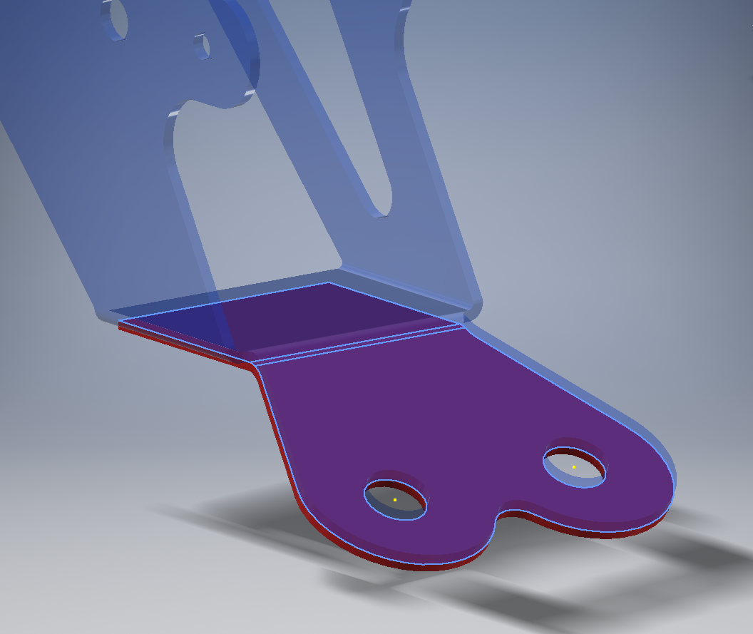
This is a sheet metal part for the P-39 Airacobra (#12-509-052) sent to me by a fellow enthusiast for comment. Before I get immersed in discussion on this subject I would just say that this part is a cable cover that is unlikely to be under any substantial stress and thus would probably be fine as modelled.

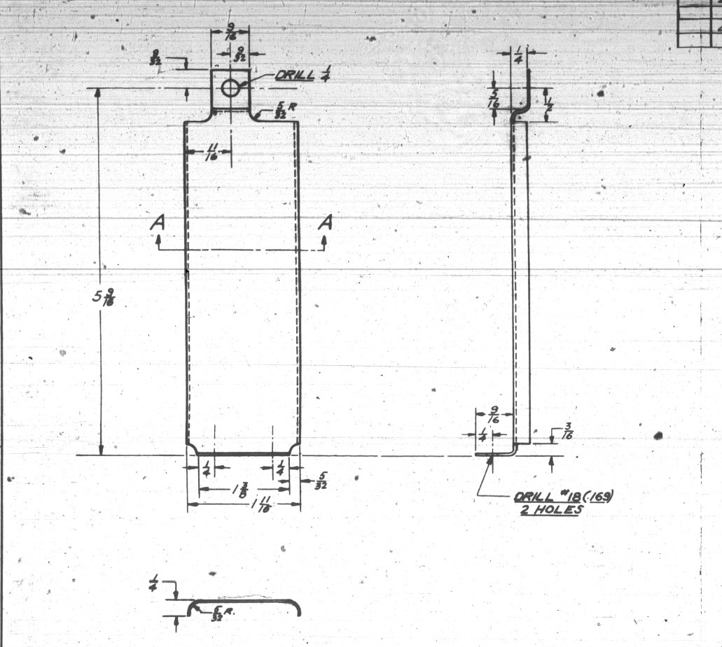
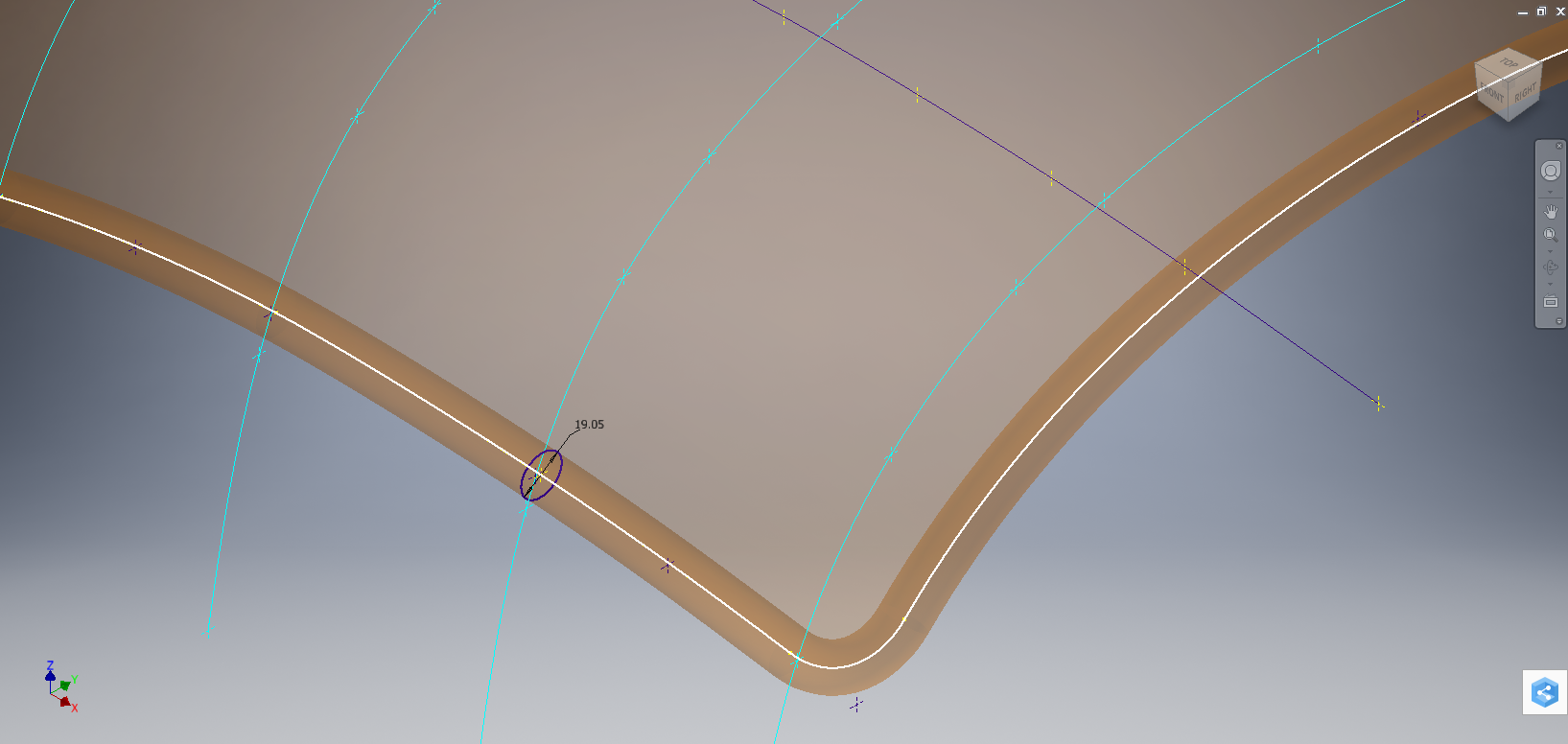
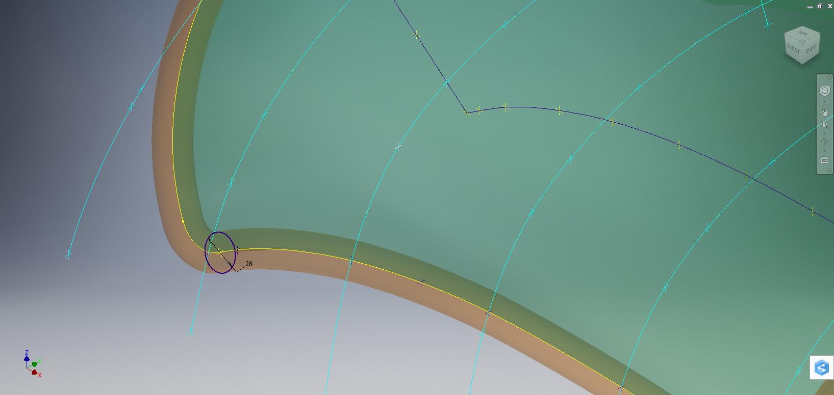
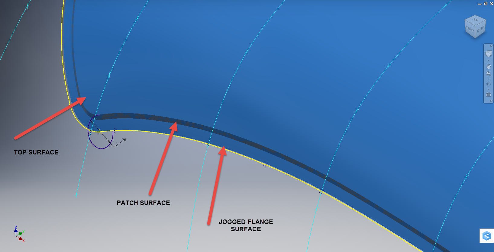
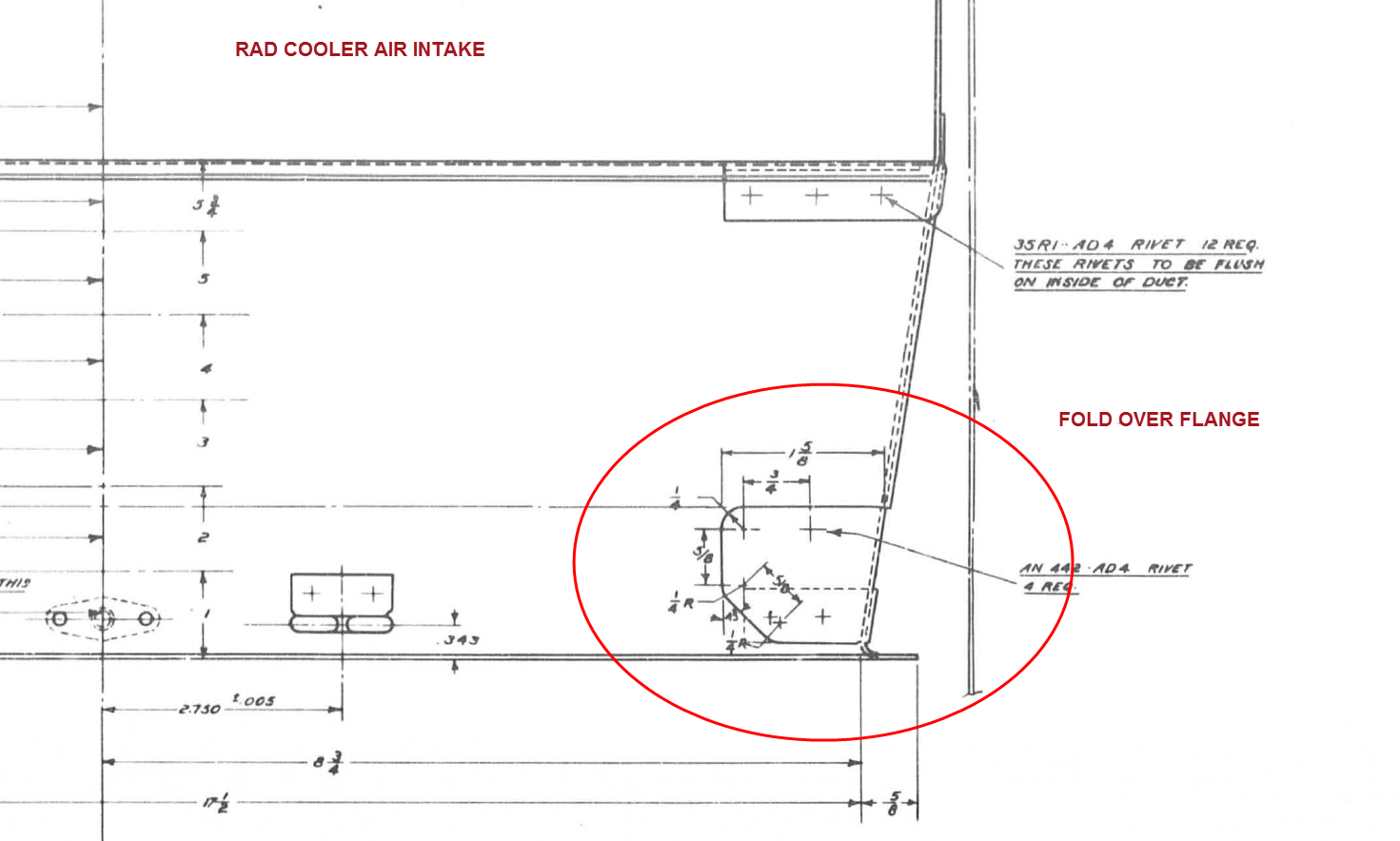
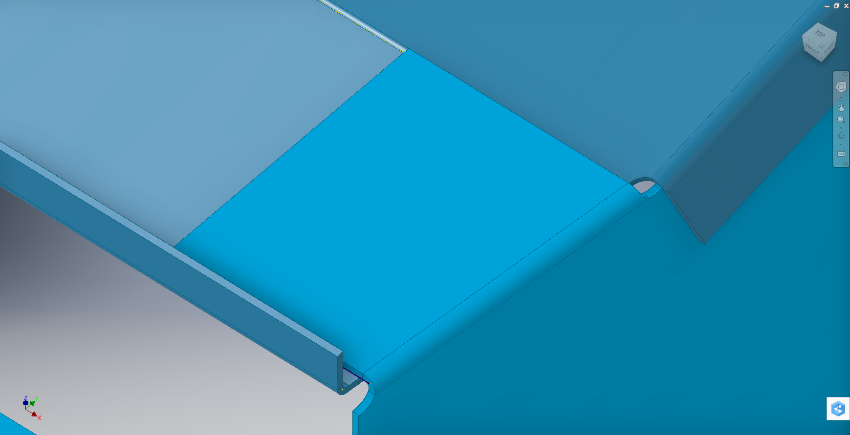
The part comprises 2 tabs, one on the top and one on the bottom. It is the fillet radius that I will focus on. The first bend is offset from the edge of the plate. The drawing specifies a 5/32″ (4mm) radius for the fillets at the intersection of the top tab and the main body which overlaps the sheet metal bend. The originator has taken this literally and attempted to create a finished fillet of 5/32″.

I suspect that the drawing is actually referring to a 5/32″ radius as it would be for the developed flat pattern because doing so otherwise; due to the bend being offset as illustrated on the cad model; this introduces stress points.

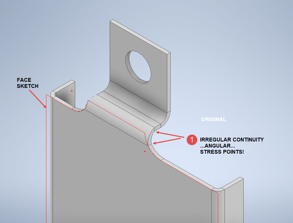
The images show the irregular continuity which creates angular edges that essentially become focussed stress points. It is often best to try to achieve smooth continuity both for bending purposes and of course when in use. What they did was sketch a face profile; which included the specified radius (#1)and then proceeded to adopt the standard commands to build the flanges. Technically it is not wrong but as the manufacturer’s drawing does not contain a developed flat pattern it is often misinterpreted…the radius should perhaps be applied to the pattern before bending.

Similarly, at the bottom tab, we also have irregular continuity as shown at #2.

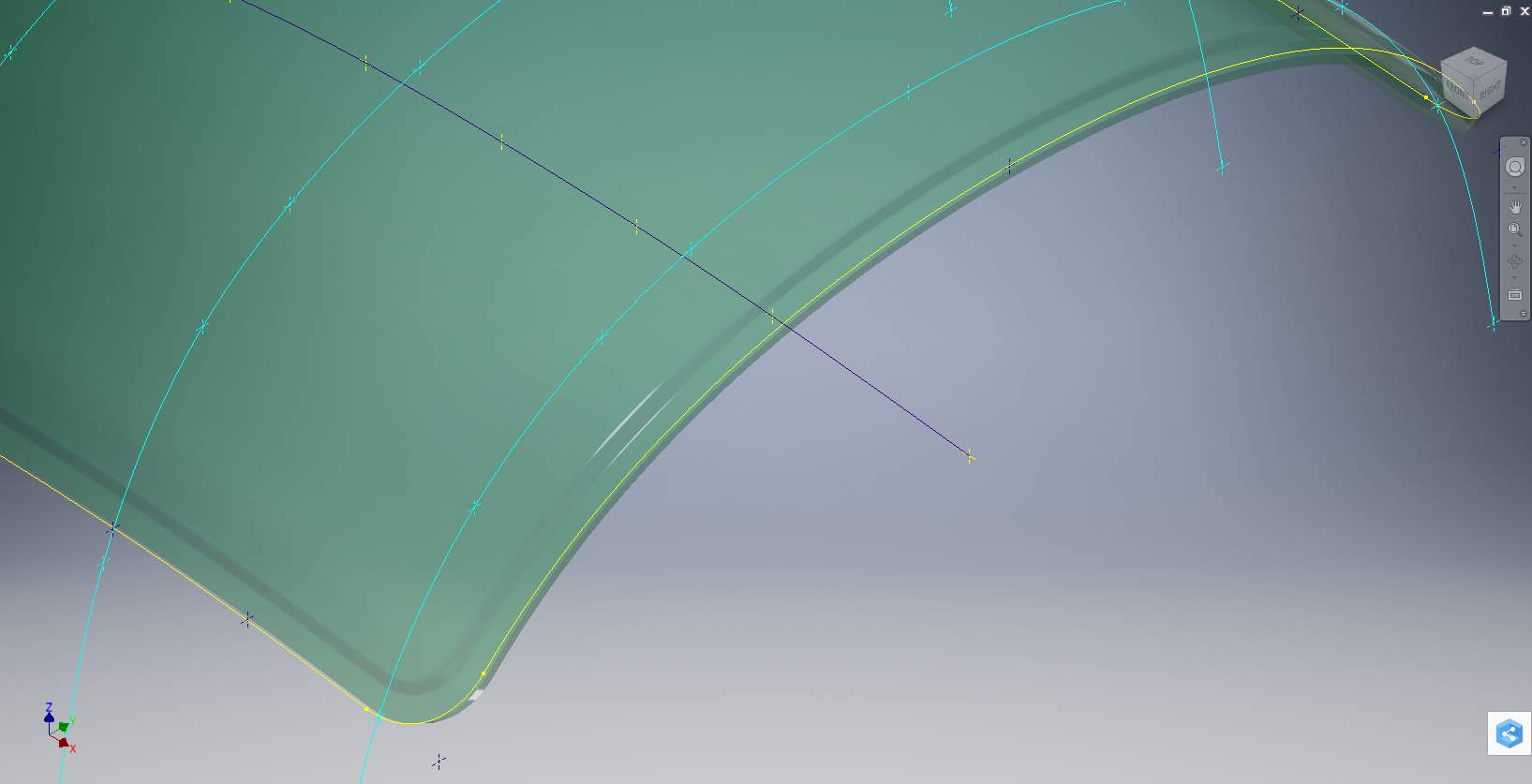
I rebuilt this model to address these issues and you can see how a small change in modelling technique can obviate some of these issues.

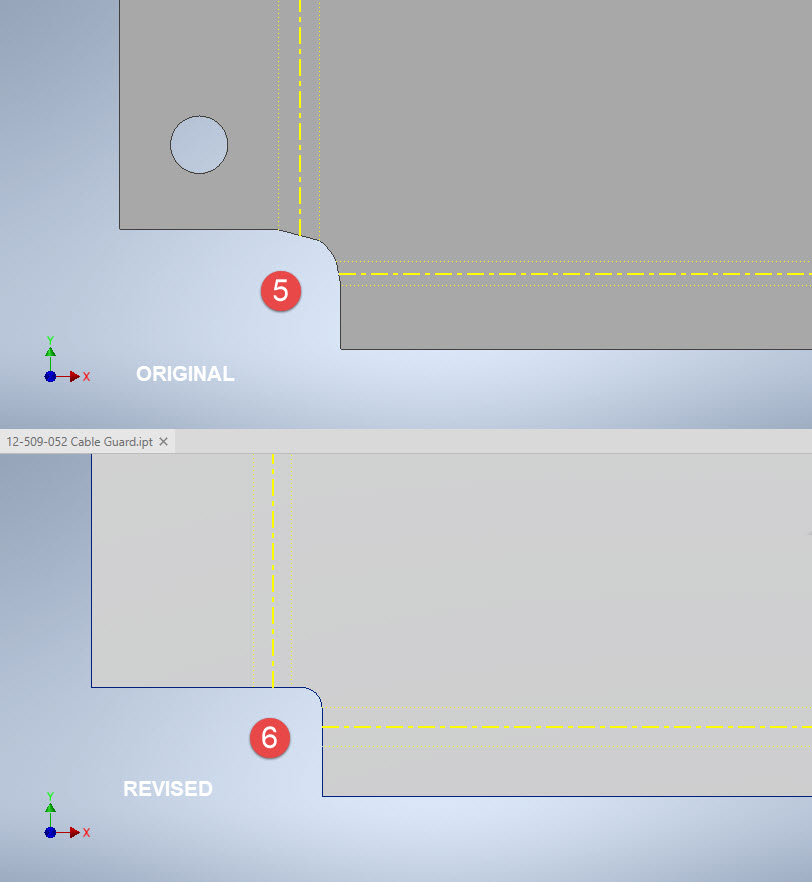
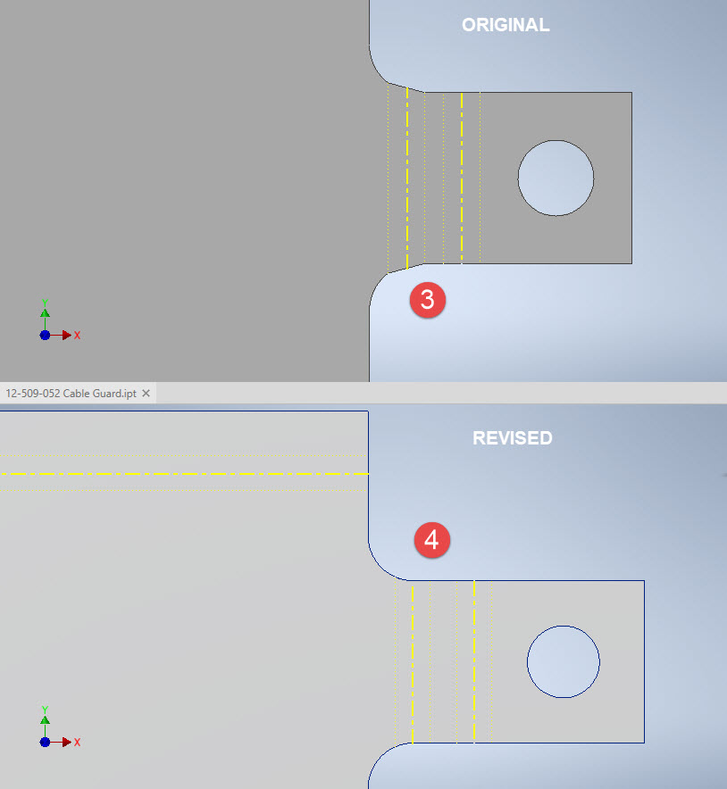
The images show the developed pattern with the original cad model on the top and the new version on the bottom. At #3 the outline of the tab would be difficult to cut with the small taper before the fillet, whereas the lower profile at #4 is easier to cut with no stress points. Similarly for the base tab at #5 and #6. I should note that the bottom tab radius is not specified so I opted for the default minimum which fits nicely before the bend lines.

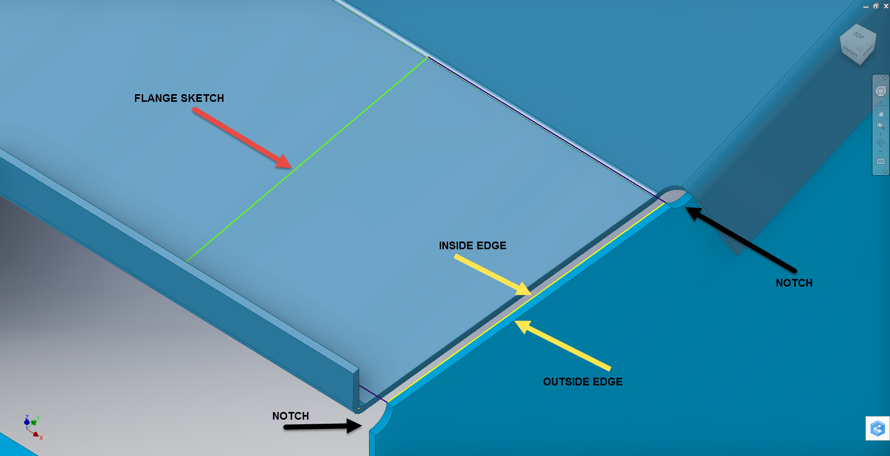
There are several ways to do this with the easiest being accomplished by using the Unfold command on a square flange and then applying the fillet before refolding. The option I have used here is first to draw an extended flange as part of the initial face sketch, create the first part of the model as a Face then apply the 5/32″ fillet before bending along a predetermined bend line sketch.

The sketched tab outline is a lot bigger than is required which of course can be trimmed once the tab is complete. You can see the extents of the tab on the initial sketch…you only need to add a plane at that point to trim. The resulting fillet is a smooth continuity with no obvious stress points.

Understandably the designers wished to increase the amount of material at the bend to maximise strength so it is advised to try to achieve those goals. As I said before, for a cover like this it is probably not too critical if we only applied a small fillet but for framing and structural elements, it may be critical.

One quick note on the 2 vertical flanges…the drawing specified an internal radius of 5/32″ which to be honest is unworkable as the resulting bend would overlap the bottom tab…in this case, I opted for the minimum specified.

At the end of the day, it is down to the interpretation of the designer intent. For the majority of sheet-metal drawings, they often do not include developed flat patterns but may contain information that is actually applicable to the flat pattern and not necessarily the finished folded profile.

Hoppers: Surface Model for Mass Containment

Hoppers: Surface Modelling for Mass Containment:

Although not directly associated with aircraft design there are inherent modelling techniques equally applicable to many aspects of aviation. The techniques relate to surface modelling for the containment of a known mass or volume. In each case, the criterion is the specified volume or mass that ultimately defines the size and shape of the container.

hopper-1

This particular hopper is for a Transfer car used to feed Steel Plant Coke Ovens with coal. The development of this hopper combines surface and solid objects in a single multi-part model that is configurable via a dialogue populated wth the key parameters. Surface modelling can be used for various purposes; some of which I have covered in previous articles for the creation of sheet metal flanges, trimming solids and providing a boundary for extrusion or as a containment for a solid component; as I have used here.

hopper-master-01

This type of hopper is fed from an overhead bunker and releases the fill material through an aperture in the base. The mass volume is modelled according to industry specifications that define the slope of the poured coal defined by the size of the top bunker opening.

The surface represents the containment boundary which has zero volume and zero mass therefore by definition will ensure that the only properties recorded for mass and volume in the 3d model relate only to the fill material. The image above shows some of the key parameters used to model this hopper as a part file with an ilogic form to make it easier to adjust the parameters to suit the project design.

2013-09-17_121727

The gray values for the Coal Volume and the Centre of Gravity are the results calculated from the physical dimensions of the coal mass and the containing surface model. Once the correct dimensional and mass properties are determined the surface objects are extrapolated using the “Make Component” command in Inventor which creates a separate derived part file and also (optional) includes the part file in an assembly placed at the original coordinates. In the surface part file we simply thicken the surface to generate the solid plate material that will form the structural body of the finished hopper.

hopmaster01assemblya

This is a very basic introduction to using surfaces where the mass or volume of a fill material is the critical component. On some forums, similar questions have been asked for complete hoppers where programmed solutions are offered to subtract all the structural objects to derive the fill mass and volume. By using surfaces with zero mass and volume to contain the fill there is no need for any programming solutions. There are a few ilogic basic routines included in this example for formula calculations and shifting the location of the bunker output. Another example just for reference is the casing for a screwfeeder:

400 - Streams 1 & 3.png

Surfaces are extraordinarily versatile with many applications, only some of which have been mentioned in this blog. For this example, we could extend the technique to modelling fuel tanks, hydraulics and oil tanks where the volume and mass are critical.

Sopwith Pup: Technote

Sopwith Pup: Spar Clip Technote

The Sopwith Pup is a single seater biplane built by the Sopwith Aviation Company, another aircraft in my archive, though not one that I have done much work on. This is just a quick technote; so not a new project; my priority still lies with the P-39 Airacobra.

I received an email from a close friend and he asked if I could help him out with this model for the main spar clip, item number 1393-1 from the Sopwith drawings. The area in question was the cable lug at the base of this clip, which comprises 2 parts.

The problem related to matching the profile of the top part to the profile of the lower part, without extensive or complex modelling. For the lower part, I decided to use the sheet metal features to create this as a multi-body part which I would then use as a template to profile the upper section that is essentially an extension of the main model.

What he was trying to do was project a sketch from the each face of the lower part, extrude each sketch and then fit a bend to connect the two extrusions. He reckoned this was more complicated than it should be and asked me if there was better way of doing this.

He was actually not that far from achieving a simpler solution, he just needed to adapt the process a little bit.

sc-03

In a previous article for the P-39 cabin glass I discussed the merits of selecting the solid surfaces as a means to modelling the jogged edges. I have used a similar technique here for developing the upper part of the lug.

Simply by selecting the top surfaces of the lower part as shown above; we then apply a thickness to this selection and opt to merge with the upper part as shown. There we have it; an exact match and fit between lower and upper lug parts in one step!.

It looks simple and often the best solution is, but occasionally it is easy to overlook the fact that we can manipulate the surfaces of a single solid model to create new separate parts without too much effort.

sp-05

Squaring the Edge:

The Sopwith drawings for this part and many other similar parts are a little misleading given that they show the edges of these components as beveled. This is normally not good practice, particularly when metal meets timber. Ideally we need to square the edges to negate this problem and to facilitate the cutting of the developed sheet metal pattern.

sc-06

These brackets are an awkward shape which requires some careful planning to ensure that the model is correct and can be manufactured. So to achieve this I occasionally use surfaces to set-out the basic cut profile shape and then thicken.

Thickening a surface model is actually a good way of working due to the thickness being applied normal (perpendicular) to the surfaces, thus by definition achieving a good square edge to the developed pattern.

As you can see in the image on the right the edges are square and easy to cut.

The other way of doing this is using the cut option feature from the sheet metal command.

sc-10

By selecting the “Cut Normal” option in the dialogue this will ensure that each of the edges from this extrusion will be square to the surface when flattened.

Whilst we are on this subject; the weld seam at the top of this bracket is something I would consider improving by having a thin continuous metal strip either side of the seam instead of 3 smaller widths (top image) which may distort the metal, something like this (A):

sc-11

Notice I have tidied up the bend at (B)…this gives a much cleaner profile when the draft angle is quite small. I should note that I don’t normally take liberties wth the manufacturer’s details, but occasionally exploring options to see how things could be improved can be quite an interesting exercise.

I should note that it is normally good practice to state on the 2D manufacturing drawing a “Break Edge” minimum size anyway for all edges even when square cut.

Bell P-39: Cockpit Glass

Bell P-39: Modelling Curved Cockpit Glass (Inv 2017)

Modelling the Cockpit glass can be a challenge to achieve the correct curvature and create the inevitable jogged and profiled edges.

P-39 canopy

The Bell drawing lists all the ordinates to enable us to create the profile sketches from which to derive the required basic shape with two areas worth extra consideration in respect to the rounded corners and the jog along the perimeter edge.

We developed the initial extruded surface from the contour ordinates and then simply extruded a sketch to trim this surface to the basic shape.

P-39 c1

The first thing we need to do is to fillet the corners. In Autodesk Inventor we cannot fillet a single surface, though we could use various techniques to do this we decided instead to Thicken the surface an arbitrary amount ( it does not much matter how thick it is) and then apply a fillet of each corner of the solid which ensures correct tangency.

P-39 C2

The jog along the edges is a bit tricky, given the nature of the surface. One way of doing this would be to sketch the jog profile and sweep the profile using the edge as the path. We tried this in several configurations but the result was not consistent.

To solve this we need to consider what a solid comprises off in order to rethink our strategy. A solid is essentially a series of closed surfaces that are used to contain the solid properties. With this in mind, we started by offsetting the top surface to create a copy at the desired jog dimension inward. Along the edge of this new surface, we sketched a circle with a radius the same as the jog flat dimension and swept this along the perimeter of the new surface.

P-39 C20

By using a circle profile for the sweep we ensure that the resulting flange; which is trimmed from the copied surface; will be a consistent width throughout its length. Now we have a surface representing the exact dimensions of the jogged top face at 3/8 inch. We do something similar for the top surface which is selected from the solid with the circle set to a bigger dimension to facilitate the jog transition curves. This time simply trimming to remove the edge width.

p-39 c21

This gives us 2 surfaces, the lower surface for the top face of the jogged flange and the second, the actual main surface for the top of the canopy glass. To fill the resulting gap between the surfaces we used a patch surface.

P-39 CX

We have trimmed the surfaces of the solid body thus breaking the solid cohesion leaving a number of orphaned surfaces which can now be deleted. To finish we would stitch the surfaces and then thicken to the required amount.

p-39 c12

To achieve a smooth transition when applying a patched surface between 2 surfaces a good result can often be achieved by using the tangency option relative to each joining surface. In this particular instance, the patch size was too small to do this so instead we applied fillets to achieve the same results.

A Note on Curvature:

P-39 Canopyx

It is absolutely critical to manage the curvature of the sketch profiles prior to lofting to ensure the best possible surface. This usually requires marginal adjustment to the ordinate dimensions; generally fractions of a millimetre; to achieve a good result.There is a small shoulder on this glass panel thus accounting for the slight edge deviation. To improve further the definition of the finished surface we can convert to a freeform surface which will derive a new surface with G2 curvature.

P-39 Cockpit Glass

Another Quick Tip:

Sheet metal flanges are restricted in Inventor to straight edge segments whereas with Solidworks we can actually create a curved flange where there is continuous tangency. One workaround in Inventor is to sweep a profile along the edge of the sheet metal part to create a flange or alternatively use the Ruled Surface feature.

P-39-1

This feature provides a few functions for extending surfaces either perpendicular or tangential to an existing surface. In this example, we simply select the default and create a perpendicular edge without requiring additional sketches.

Thicken the resulting surface, convert to sheet metal part and apply a traditional flange!

Bell P-39: Fold Over Flange

Technote: Bell P-39 Fold Over Flange.(Inventor 2017)

This a quick technote to highlight an issue that we sometimes come across with creating flanges in Inventor when one part is sloping away from the other.

The part we are working on is shown on this scrap view from the Bell drawings. This flange is folded over onto a sloping top plate from the side plate that is at an angle of 105 degrees.

P-39 Oil Cooler Main1

The issue relates to the reference edge selections that will determine whether or not we obtain a smooth transition from the side plate to the new flange.

P-39 COOLER MAIN5

When I first did this I selected the outside edge of the side plate to align the flange sketch. This was not satisfactory due to the notches; that are perpendicular to the side plate; influencing the creation of the eventual flange bend which gave us a rather awkward and untidy bend transition…definitely not good.

So I recreated the sketch; this time aligning with the inside edge of the side plate; which resulted in a smooth transition bend to both notched areas as shown below.

P-39 COOLER 4

Occasionally when creating flanges the selection of which edge is referenced can make all the difference in achieving a satisfactory result. Use the sheet metal Face command to create a flange based on a 2D sketch as we have done here.

I should note that those notches are bigger than they need to be at this stage. I normally develop these complex models using a generous radius until I have completed the construction. Once I have achieved a satisfactory model and everything aligns correctly then I can go back and adjust these notches to a minimum size.

Progress Update:

I have included the rear fuselage section contour lines for reference. Will probably have to leave this project for a few weeks as I really need to spend some time sorting out my garden that is slowly resembling a jungle!

P-39 Aug21

37mm Gun Mount & Rudder Cable Guide Pulley.

Bell P-39 Airacobra: Fuselage

Bell P-39 Airacobra: Fuselage

This is an update on the P-39 project. I have actually been drifting between this and the P-51 Mustang as a number of inquiries have come in regarding the ordinates and various questions on the Oil Cooler model and landing gear mechanisms; which has been an interesting diversion.

Getting back on topic, I thought it may be prudent to write a quick update on what I am doing with the P-39 Airacobra and where I hope the journey will take me.

I have of course continued working on the ordinate data spreadsheet which is derived from the part drawings themselves. This serves as a check whilst I am developing the structure. The 3D models are being developed in context, i.e the individual part models are located to the 3D spatial ordinates relative to a single datum so when I plug these into the assembly they will import to the correct 3D location thus negating the requirement for constraints.

2016-08-12_22-48-54

This is the first time I have worked this way as I usually just model the part and then constrain to the corresponding items in the assembly, but this is usually dependent on the quality of the assembly scans to clearly identify and ensure correct alignment of the parts. As we all probably know these scanned files are the most likely to have problems with legibility. In many respects having the part files modelled relative to ordinates in 3D space ensures that the parts line up correctly and I don’t have to worry too much about the quality of the assembly scans.

P-39 Airacobra Fuselage

The P-39 main assembly drawings are actually not too bad as the image above shows. This is a scrap view of the fuselage Longitudinal, comprising many small parts all riveted together to form the assembly. The area in red is where I am working at the moment; which is a major node; just aft of the engine bay; where the many struts and braces overlap on both sides of the stiffener plate. The following image gives you some idea of the detail to which this is being developed.

P-39 Airacobra Fuselage1

The pilot holes for the rivets are unique to each individual part and just like the real process of construction these holes will be match drilled to all the other corresponding parts in assembly.

Modelling the complex parts and locating all those holes takes a lot of time but I believe the end result will be worthwhile. With this degree of accuracy you could just about build one of these aircraft from scratch!.

Quick Technote: P-39-01
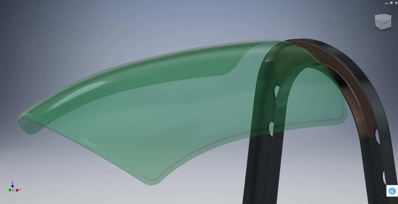
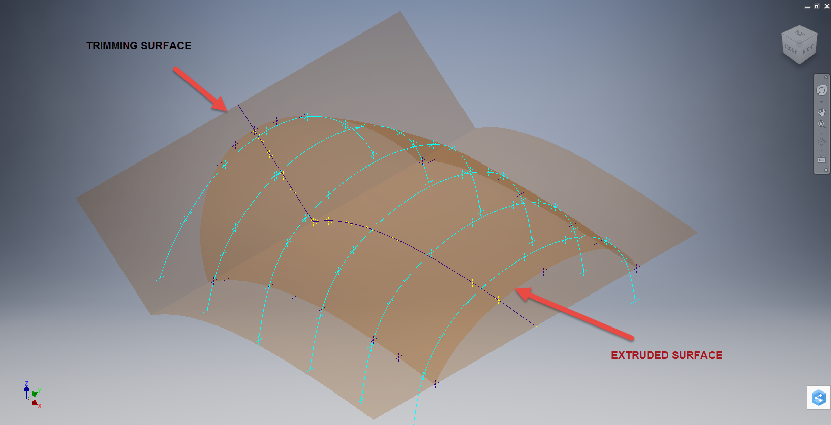
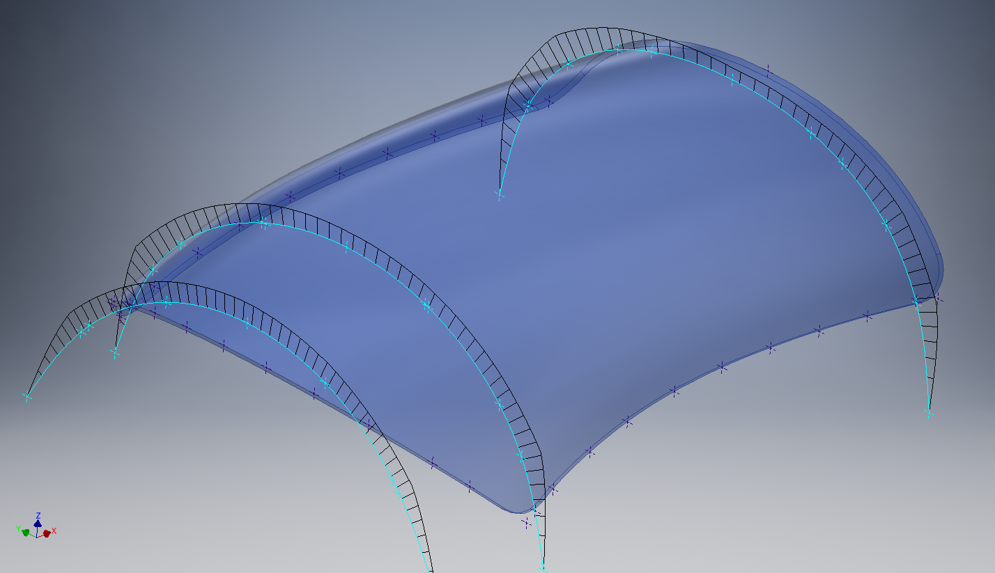
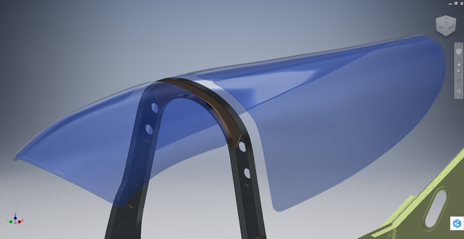
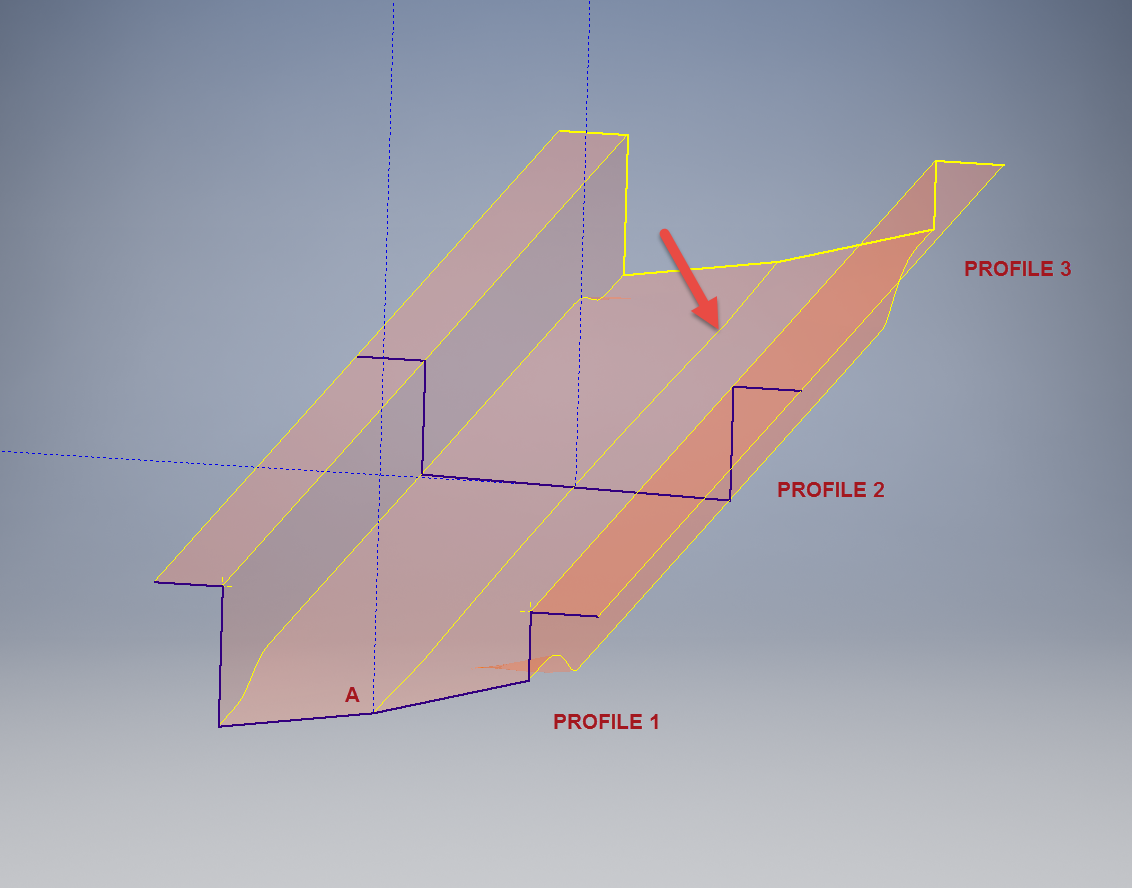
This is the lower level fuselage cross member that has a built in twist to align with the connecting frames at both ends. The model consists of 3 profiles with the 2 outer ones containing a small angular deviation in the centre at point A. Normally I would loft the profiles to create the finished surface but this projects the deviation throughout the length giving us 2 surfaces; which does not look good.

I therefore deleted the resulting 2 base surfaces and simply replaced them with a boundary surface. I’m sure you will agree the result is a much smoother gradation of curvature; that matches expectations.


Project Cad Technote: Sheet Metal Bending in CAD

Project Cad Technote: Sheet Metal Bending in CAD.

Sheet Metal Work is an interesting subject to which I could no doubt devote an entire blog to. Fortunately for us we don’t have to as this topic is covered in detail by the many professionals working in this industry.

However understanding some of the key principles is imperative to ensure that our CAD models created from the aviation manufacturers drawings are correct as the dimensions given do not always suit the CAD development process.

One particular aspect relates to something the Sheet Metal guys refer to as the Outside Setback. The Outside Setback is the distance from the apex of the outside mold lines to the tangent point of the outside radius. When the sheet metal is bent the inside radius pulls the edge of the material away from the apex of the bend.

2015-08-30_12-39-11Typically on many occasions we will have a developed profile for the part which is to be bent to the required profile with only a few dimensions noted to achieve this including a bend coincidence point and angle.

2015-08-30_12-13-10The image on the left is indicative of many situations that arise when working with the manufacturers drawings. It is not unusual for a dimension to be given to the projected point at “A” which understandably is important to ensure the part mates properly with another.

However in Inventor; for example; we only have selections at 1,2 & 3 for “folding” a part from a development sketch and no option to define the stated “Dim” to the point of coincidence; which therefore may not provide the desired result. We may of course have the angle, material thickness and usually the inside radius.

2015-08-30_12-19-11Its not practical to select points 1 & 2 but it may be possible to use point 3 if we know the OSSB dimension.

In Inventor this is the middle option from the sheet metal fold dialogue. In this case we have specified the complimentary angle (97 degrees).

In order for this to work we need to calculate the dimension OSSB. The smart guys in the sheet metal industry have this stuff all worked out and have an easy equation that we can use to ensure consistent accurate results.

2015-08-30_12-20-05

B> denotes the complimentary angle which must be less than 170 degrees.

IR is the Inside radius and MT is the material thickness. (the dot in the middle by the way is multiplication).

2015-08-30_12-25-18From this equation we derive the value for OSSB which we will deduct from the Dim value provided on the drawings, thus giving us the correct location of the fold line at point 3 above.

In this example the dimension from the manufacturers drawing is stated from the hole center, which has been adjusted to locate point 3 by deducting the value OSSB.

It works perfectly and we now have a folded bracket from a development plan that complies with the stated drawing dimensions.

I should note that some CAD products take this into account and provide the necessary options for developing this folded model but where we have limitations a touch of maths goes a long way to achieving the desired result.

In this example the hole is very close to the bend causing a slight deformation. This could initially be drilled to a smaller diameter and reamed after bending or we could simply use a smaller bend radius; if permissible!