NAA P-51D Mustang: Tail Wheel Project Update

NAA P-51D Mustang: Tail Wheel Project Update

This project is growing arms and legs; every time I check back to the NAA documentation I find yet another part associated with the assembly in this area.

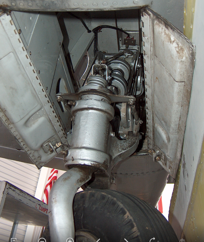
I am beginning to appreciate just how complex the interaction is with all the parts that share this very small space and wonder sometimes if I will ever complete this task!.

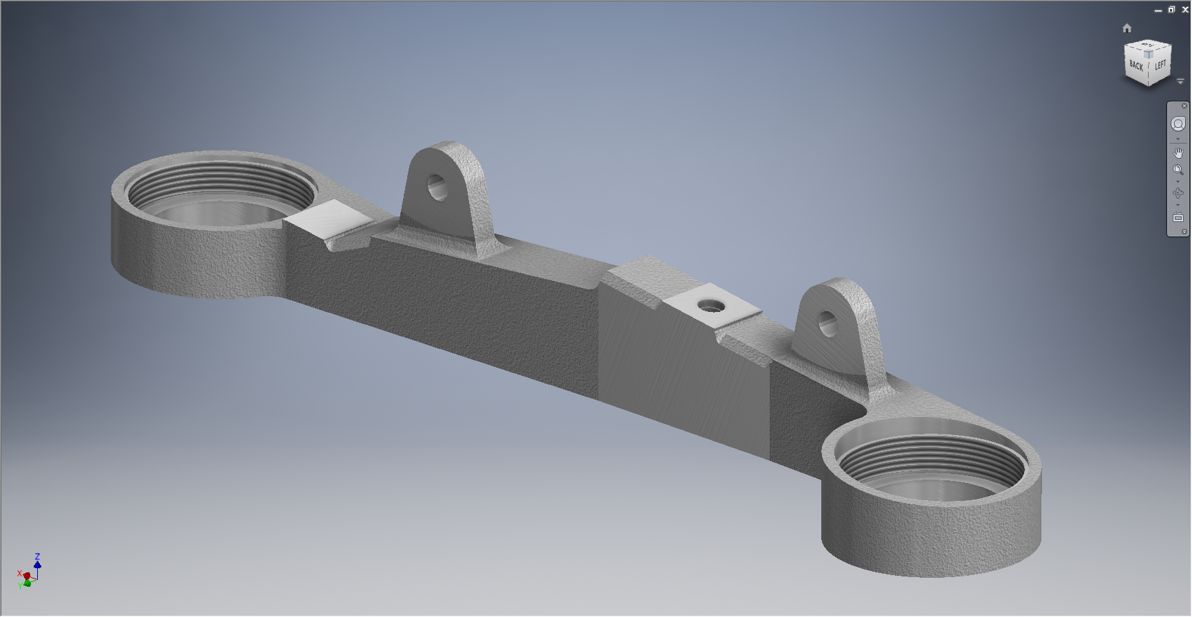
For this period of build I have had to revert to an earlier version of Inventor; which unfortunately means many of the parts already modeled cannot be included in the assembly build at this time as the version variants from a later release will not be compatible with this one. Also the material finishes are not as good as the Inventor 2016 as you can see below.

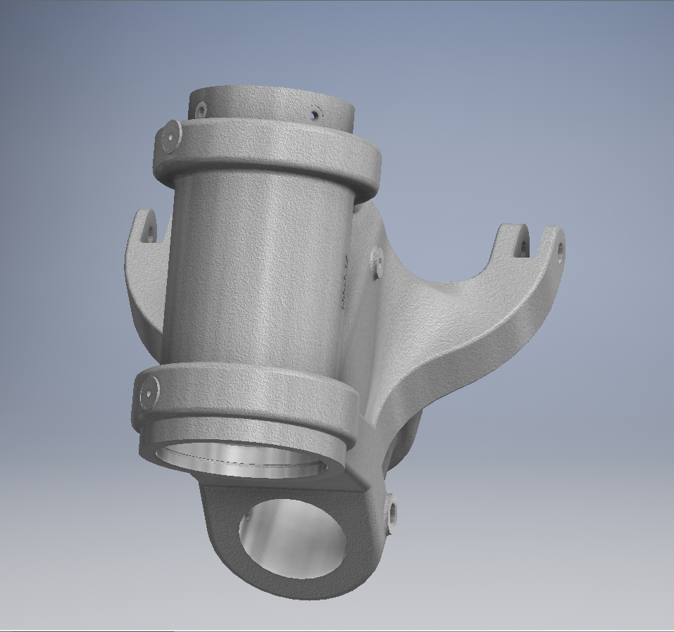
So I am focusing my attention on building the supporting elements for the Tail Wheel mechanics; including the fuselage frames local to this area.

P-51D Mustang: Rear Fuselage

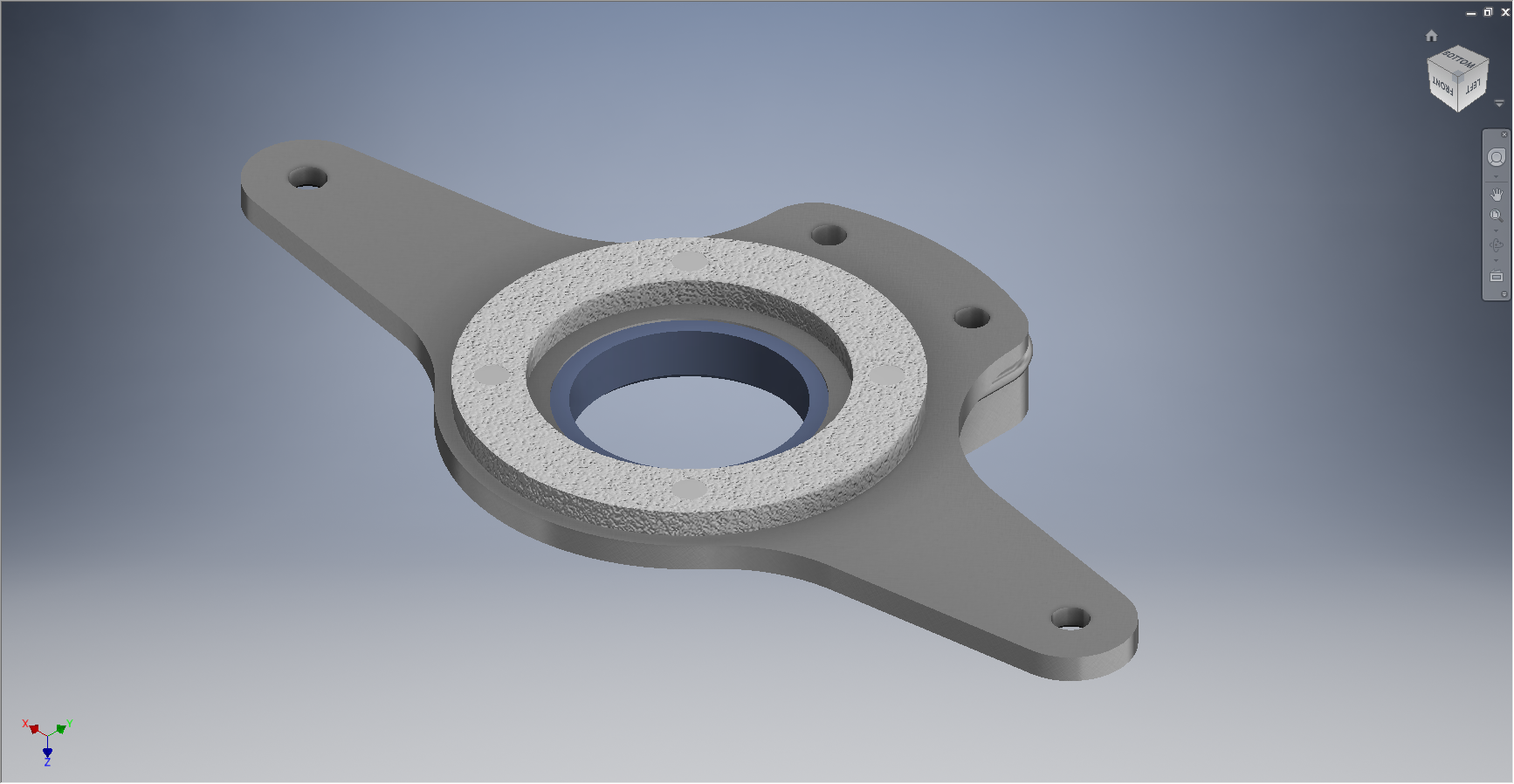
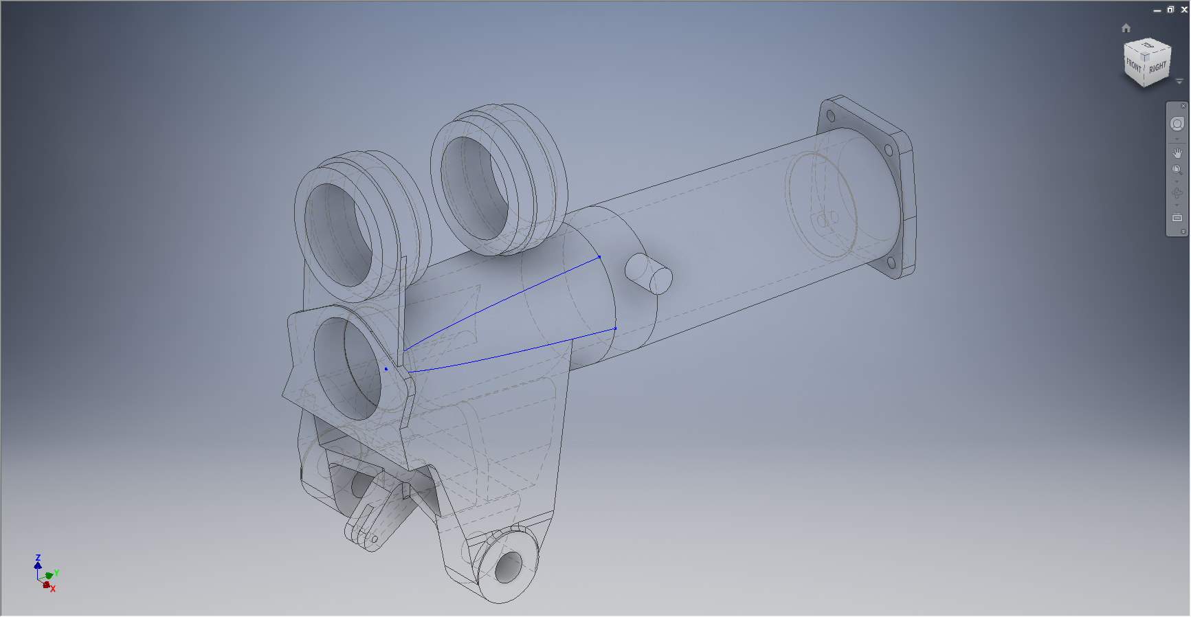
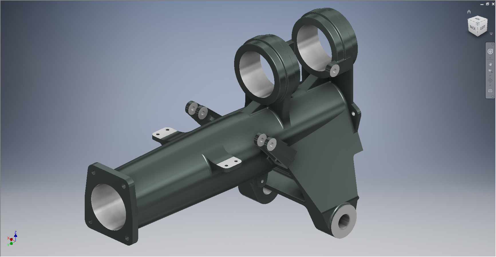
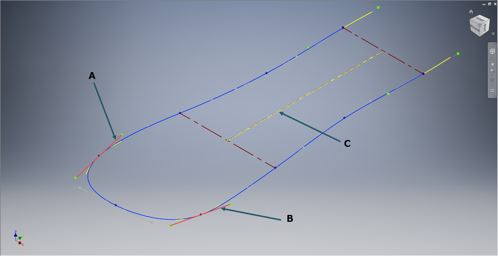
The fuselage frames are surprisingly complicated to build, partly due to the limitations of the software but also due to the flanges having to align with the surface form of the main fuselage as shown. I mainly used the sculpting technique but found that it is not possible to apply a fillet to the edge of a sculpted solid that is derived from a spline curve, so these had to be added when creating the lofting sketches.

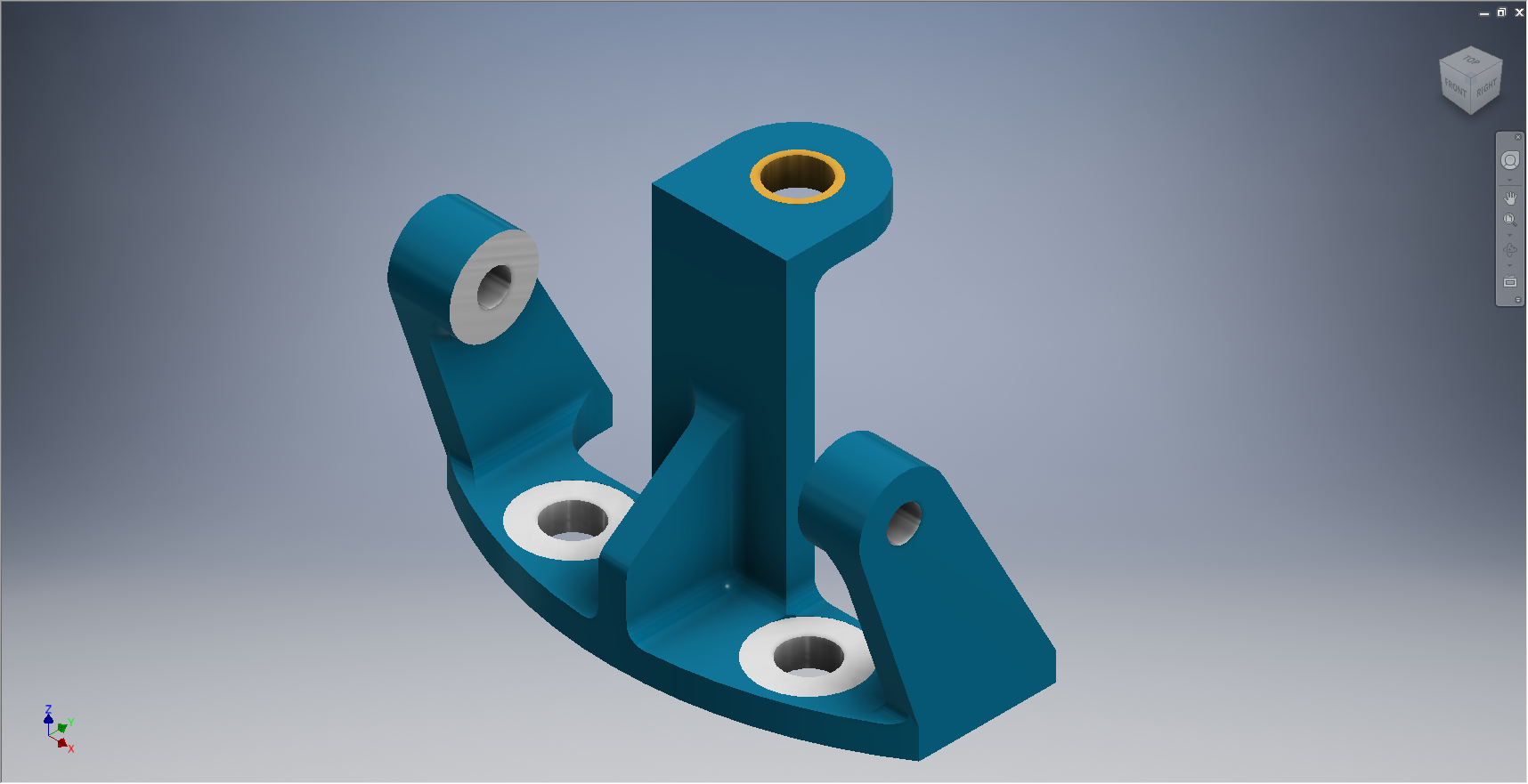
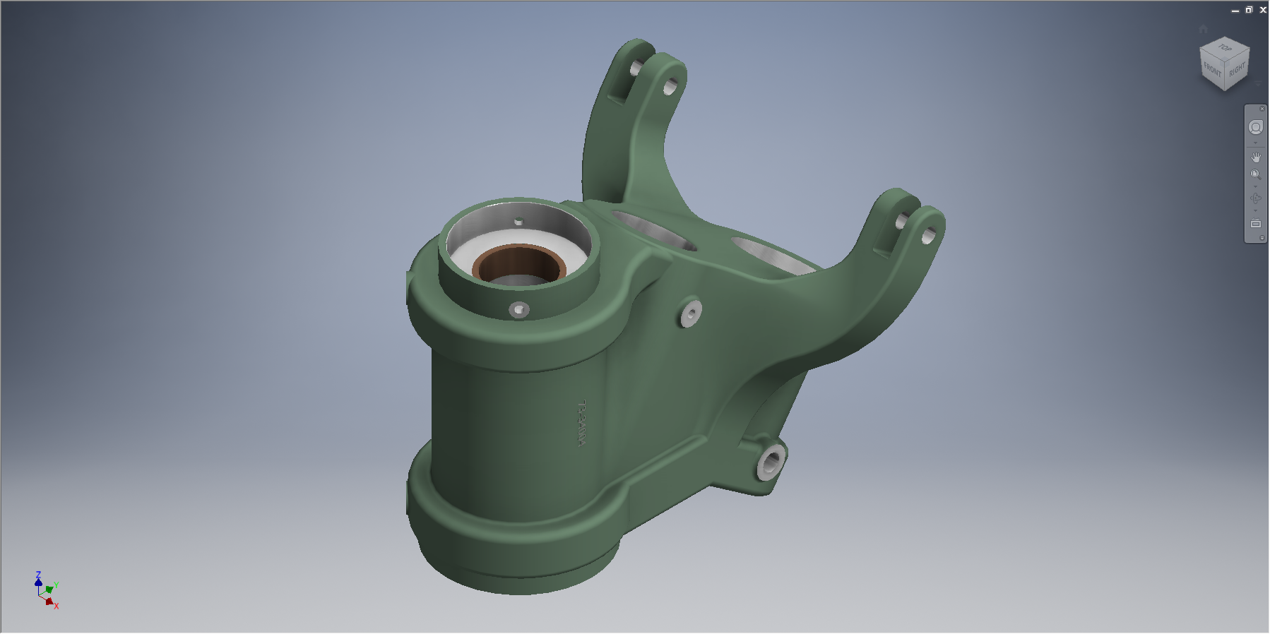
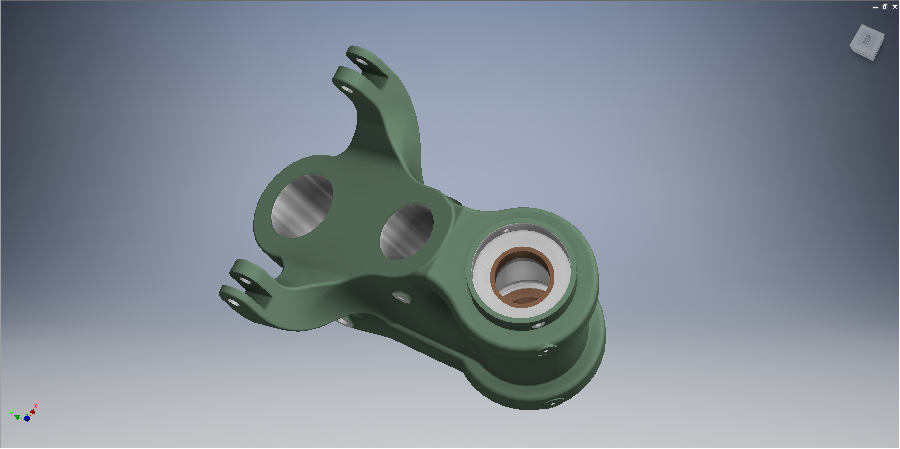
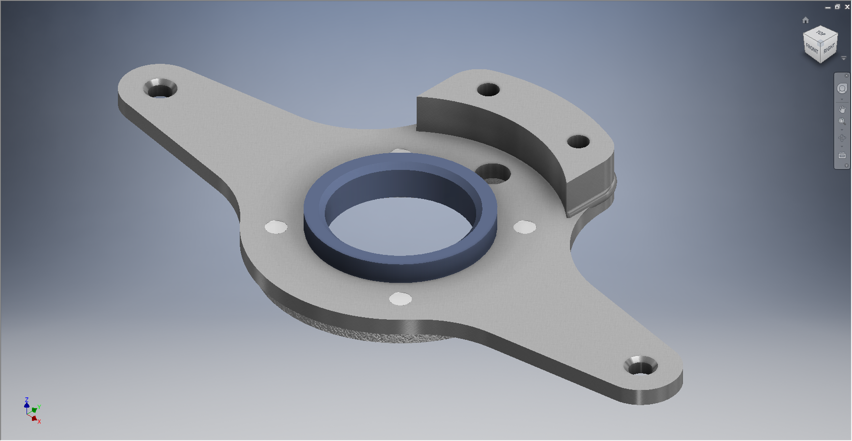
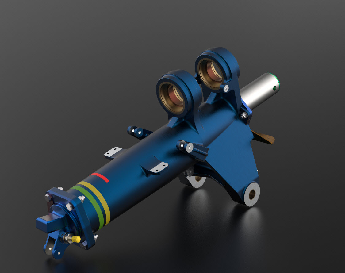
I have added a few parts (where I can) for the tail Wheel assembly; these parts in blue; and also an additional component in yellow which is a Support Assy – Rudder & steerable tail wheel control bell crank. This part by the way was a nightmare to build trying to get all the edges to align correctly with the sloping webs.

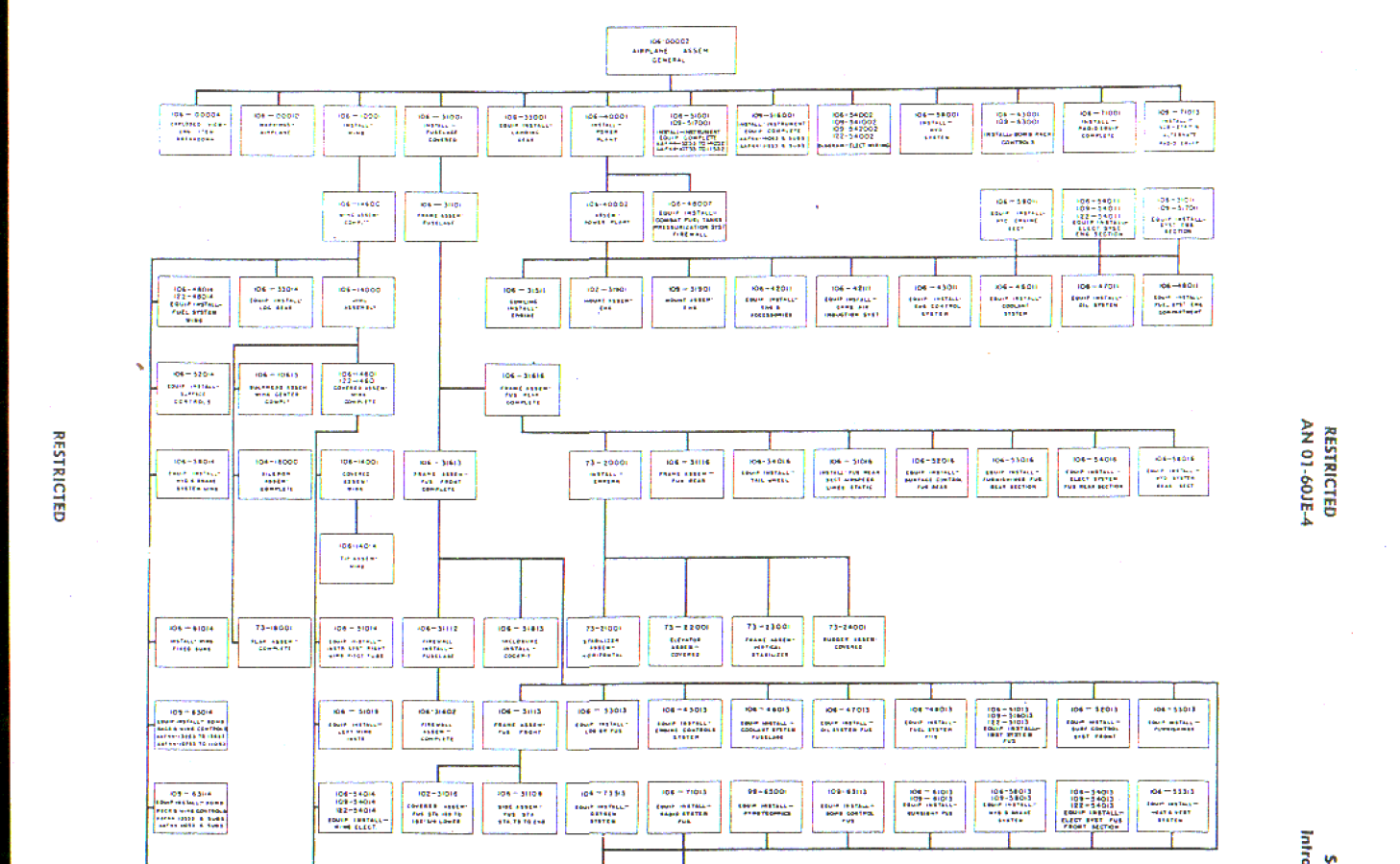
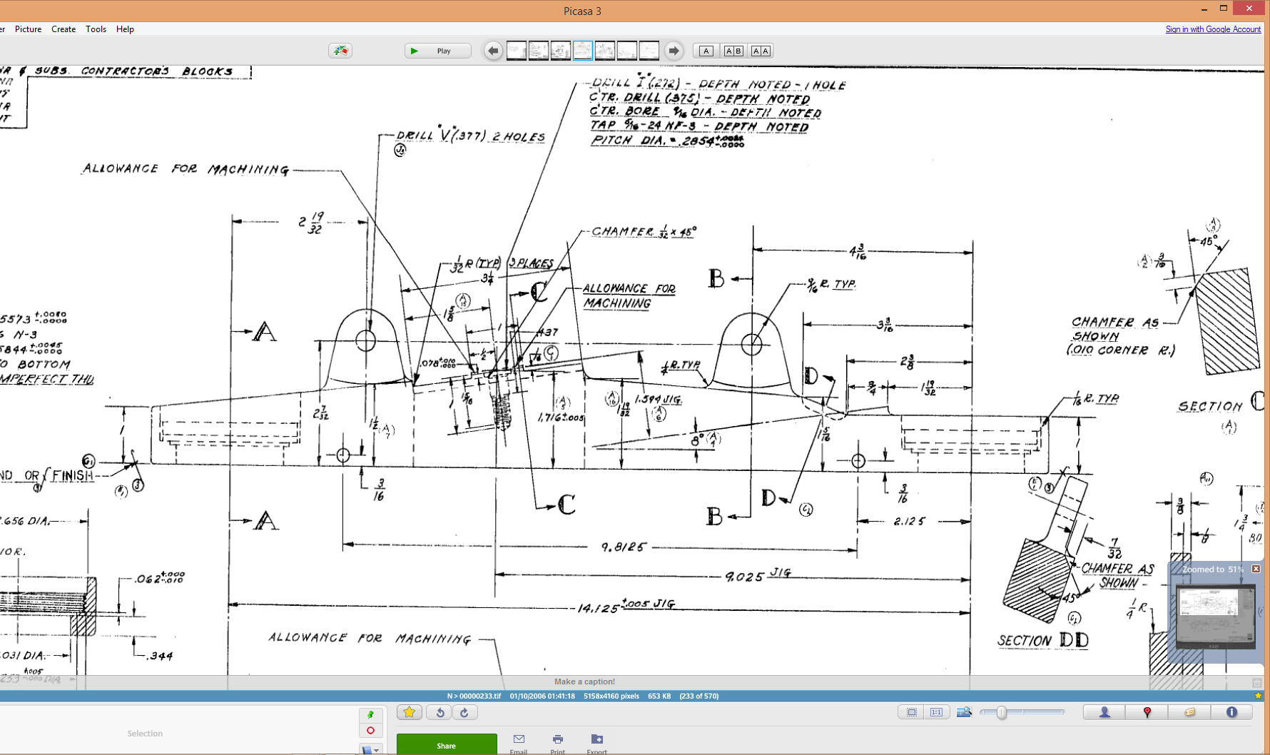
I have mentioned before the importance of having quality copies of the original materials to work with and this particular archive (from FlugArchiv) was done to a very high standard.

2015-07-07_02-06-47
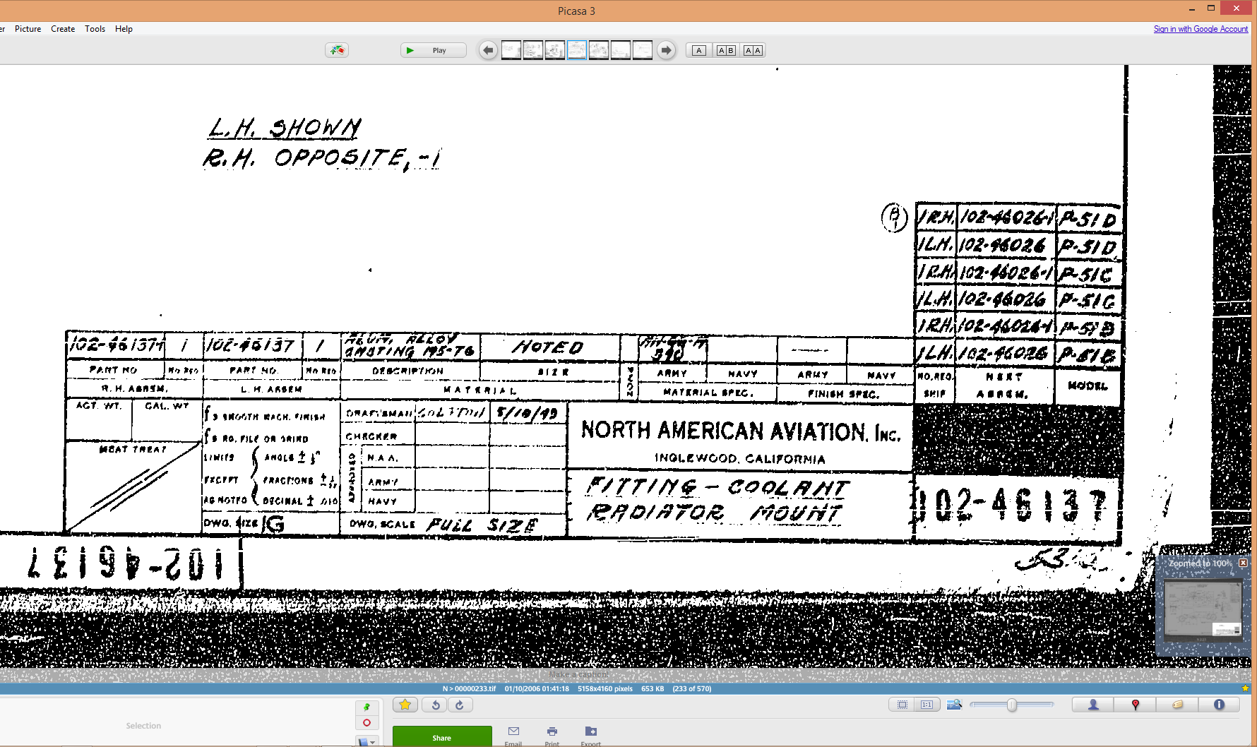
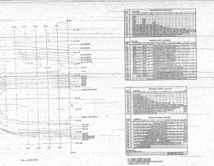
Occasionally though you do get the odd drawing that is almost impossible to use but having gained some experience in developing these aircraft structures it was not too difficult to determine the missing information.

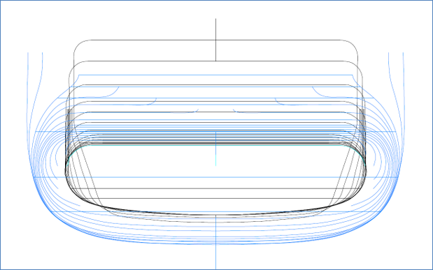
This is the one I have for the lower section of one fuselage frame.

NAA P-51D Mustang: Tail Wheel Assembly Update

NAA P-51D Mustang: Tail Wheel Assembly Update

I rather enjoy building these Cad models and the challenges they represent, however I still have a lot of work to do with organising the archive materials and the document register; which I briefly mentioned in previous posts.

I have decided to adopt a BIM methodology for the organisation and restructuring of the archive datasets and to look at the options for managing the content and format of the tagged properties within the 3D CAd models.

This all needs to be done, so I will take a break from modelling the parts for a while to concentrate on developing the above. So on this last day I decided to tackle some of the smaller parts for the eventual Tail Wheel assembly for the P-51; which surprisingly were interesting parts to build.

2015-06-26_21-14-15 2015-06-27_00-36-57

#73-34189: Bell Crank: Steering Pulley               #97-34172:Retainer: spindle lockpin

2015-06-27_18-08-13 2015-06-27_00-39-04

# 97-34191: Bracket Torque Tube Pulley      #73-34515: Bell Crank – Retract position lock

There are also a lot of parts that don’t have drawings in this archive; mainly aviation standard parts for bolts, washers, seals and bushes for which I need to knuckle down and source the dimensional information so that I can build the requisite part model libraries.

There is still a lot to consider as I move forward with this project!

NAA P-51D Mustang: Tail Wheel Down Position Support

NAA P-51D Mustang: Tail Wheel Down Position Support; Derived Parts (Inv)

I mentioned in an earlier post that we don’t have many of the forgings/castings for this aircraft but the few that we do have are not stated as such in their description and thus occasionally overlooked.

In this case the forging/casting was noted in the NAA machining drawing; which I do have.  This gives me an opportunity to explain one of the strengths of the Autodesk Inventor product, namely derived parts!

Derived parts are a powerful but easy-to-use tool that comes in two basic flavors: you can derive a part from another one, or you can derive a part from an assembly. Using derived parts, you can easily create machining models and drawings from an as-cast model, and you can create a mold from the same model.

2015-06-25_23-39-08 2015-06-25_23-38-08

These images show the casting model I created from the original NAA drawing #73-34162 for the Tail Wheel Down Position Support.

This model took me quite a while to do due to the creation of all the fillets which got a bit crazy sometimes and I ended having to redo them several times to get them the way I wanted.

2015-06-25_23-39-27 2015-06-25_23-37-48

The machining model is a separate Cad part file created from NAA drawing #73-34161 which has the casting body and sketches derived from the first Cad model above. I can now go about working on the derived model; creating the machined elements and holes; without affecting the original model file above as shown.

The great thing about working this way is that should the original casting model change then this will be propagated to any other cad part files to which this item is derived but conversely any changes in these Cad part files are not reflected in the casting model.

I still have a few minor details to finish this model but thought it may be prudent to touch on the derived part capabilities of the Inventor product.

Another use for derived components is when you only have Inventor LT (Lite version) which is a parts only product and unlike its big brother does not handle assemblies. Using the derived feature it is possible to create a proxy assembly for checking the alignment of parts as shown below.

This is the armor plating for the Mustang P-51 Firewall; with the top section modeled separately from the bottom section. In this example, I have derived the top part into the lower part file as a surface model to assess the alignment and curvature continuity.

NAA P-51D Mustang: Tail Wheel Progress Update

NAA P-51D Mustang: Tail Wheel Progress Update

I’ve been busy building the 3d models and working through the vagaries of the Mustang P-51 Tail wheel assembly. This is a selection of the new parts built to date:

Mustang P-51 Spindle
#73-34004 Housing Tail Wheel Spindle
Mustang P-51D Spindle
#73-34004 Housing Tail Wheel Spindle
Mustang Idler
#99-34153 Support: Tailwheel Declutch cable idler
Mustang Bell Tail Wheel Door
# 97-34502 Bellcrank: Tail Wheel Door
#73-31114: Support: Tail Wheel Shock Strut
2015-06-23_14-51-42
#73-31114: Support: Tail Wheel Shock Strut
Mustang P-51
#97-34120 Mast Assy – Tail wheel steering
Mustang P-51
#97-34120 Mast Assy – Tail wheel steering

This last image is a photo showing the Housing for the Tail Wheel Spindle with the model in a similar orientation and finish for comparison.

2015-06-22_16-57-13           2015-06-22_12-21-05

For the latest version of these models please refer to this article.

NAA P-51D Mustang: Tail Wheel Housing EndCap

NAA P-51D Mustang: Tail Wheel Housing EndCap

Mustang P-51 Tailwheel Housing End Cap     2015-06-20_14-36-17

This item #91-34005 is the cap to be fitted to the end of the tail wheel housing described in the previous post.

The drawing that this was based on details the finishing and machining from a forging. Unfortunately and is now seeming to be quite typical for the tail wheel area again I am missing key information…its not that the drawing is lacking the necessary detail for its intended purpose as it is based on an existing unit its just that I don’t seem to have the existing forging drawing as a reference.

2015-06-20_14-48-06

The missing information; relating to diameters and material thicknesses; would have been on the forging drawing and the draughtsman did not really have any cause to replicate this information on his finishing drawing…though it would have been enormously useful!

However this is not always the case as depending on the draughtsman some do include this type of information as reference dimensions.

I have therefore interpolated the missing details as best I can based on the information available and where possible cross referenced against other drawings.

The forging drawing is actually listed in the NAA register but the archive record lists the wrong reference drawing so its likely that there is a copy of this forging somewhere in the archive!

For my initial purposes though I think the data is sufficient for the end goal of creating a working tail wheel assembly as part of the mechanism study.

NAA P-51 Mustang: Tail Wheel Housing

NAA P-51D Mustang: Tail Wheel Housing

In my endeavors to develop the assembly and parts register I have made some progress determining the associations in conjunction with the listing in the NAA documents. I have started with the Tail Wheel assembly,which actually has 59 drawings for the sub assemblies and parts…it was surprising the number of drawings just for this one area!

2015-06-19_02-13-55This is a partial screen shot of the assembly register; again divided by sub-assembly level down to the individual parts.

Having collated this information I started work on building the 3D Cad models, starting with the Tail Wheel Oleo Housing.

2015-06-19_02-08-13This housing is perhaps the most difficult model in the series for the Tail Wheel and it has given me problems.

The main lower bracket struts are shown in the end view on this drawing as being tangent to the main body housing but the side view suggests that the alignment is lower than the centre and therefore not tangent. The main body is tapered from the middle of the main body so a tangent with the lower struts would be difficult to achieve…I know I tried it and the geometry was complex.

I wondered if this should be tangential as is typical of these types of castings. Sometimes its not too clear what the intent of the designer was and this drawing sure would have benefited from the inclusion of an additional section through the strut.

I couldn’t be sure what the intent was here and the plan view did not present any new information, however I did notice a small detail for one of the side brackets with a solitary single line that turned out to be a reference for the interface with the struts and confirmed that in fact this item is not tangent!

2015-06-19_02-06-10This is the work-in-progress model which shows the generated profile of the junction between the main body and the lower struts, which satisfies the main details of the drawing.

As it turns out the strut is tangent but only to the edge of the end of the main housing and not the main body itself. There is also a glimpse of a side mounting bracket which will be quite complex to model due to the nature of the curved profiles that will need to be developed individually and then lofted to define the final surfaces.

Update: Finished model for the Tail Wheel Housing item 91-34003. To complete this sub assembly I just need to add the bushings.

2015-06-19_15-05-59 2015-06-19_15-05-04

These models and several others are now available on CGtrader

NAA P-51B/C/D Mustang: Radiator Coolant Mount

NAA P-51B/C/D Mustang: Radiator Coolant Mount

I discussed in my last post the development of a comprehensive drawing register for the P-51 and my rather ambitious intent to derive the list of parts associated with each sub assembly and main assemblies.

This could indeed be quite a task as for example on the P-51C alone we have 348 assemblies listed, some are sub assemblies and some are top level assemblies. The challenge is organizing the drawing parts list according to their assembly and retain the order of links on my filing system as per the main document register.

2015-06-15_18-18-30The NAA Numerical part lists (AN01-60JE-4 Section 2) give us some idea of how this data can be collated but the chart lists the top level assemblies and does not follow the hierarchy to the individual part. The individual parts though are listed in subsequent chapters of the parts list.

The part files themselves also contain information to assist with establishing the hierarchy of assembly; similar to the following for the Radiator Coolant Mount.

2015-06-15_01-15-12    2015-06-15_00-46-18

As you can see from the scans this part drawing typically lists the associated next level assembly, quantity and the aircraft variants to which they belong.

2015-06-15_01-19-41This image on the left is the next level assembly (sub assembly) which shows the inclusion of fittings and bushings and again lists another next level assembly.

Typically this is how the hierarchy works and its great that we can track the target assembly from the individual part drawings.

2015-06-15_00-56-52This is the top level assembly as noted in the above drawing. Our Coolant Radiator Mounts are highlighted in red.

In this example we don’t have all the drawings for the parts listed and though it would seem unlikely to be able to build this assembly with incomplete information it may be possible to interpolate sufficient data from what we know to develop the parts that are not available.

This is typical of these types of projects as the majority of scan drawing sets are incomplete and many parts can only be developed from physical examples or interpolated where we have the requisite data from other sources.

This approach is similar to how I plan to tackle this document register in identifying the links between the part files and the assemblies. We have the NAA register; which is a great starting point; and the part and assembly files themselves. There may be instances where the information from the drawings or the NAA register is unclear, in which case I would refer to other drawings in the series that may reference this information in the notes or comments.

2015-06-15_23-39-34At this stage I have transposed the NAA register assembly chart (noted above) into a spreadsheet format so that I can add additional key information.

The image shown here is a partial screenshot of how the fuselage data has been organised, showing the hierarchy level of the main assemblies according to their respective position in the NAA chart.

The first column is a reference number I use for hierarchical lists of this nature. There is still a lot of work to be done to collate the parts associated with these assemblies; hopefully most of which I will be able to transpose from the NAA scanned register.

In the interim I shall continue to develop some of these part drawings into accurate 3d cad models.

2015-06-15_00-48-28

Autocad Inventor: Splines

Spline Technote:

Splines are an absolute necessity when developing the finished profiles from the ordinate points; which occasionally throws up some unexpected results.  Invariably at some point we need to manage the curvature of the splines in order to achieve the desired result.

2015-06-09_10-15-47

The image shown here is a screenshot from the NAA P-51 fuselage station profiles, which shows clearly the ideal curvature for each station.

This image can be overlayed in CAD to serve as an aid to achieve the correct spline curvature.

Actually manipulating the curvature of a spline needs to be done in a manner that achieves symmetrical results on both sides of the fuselage station profile.

I was working on the tail-end profiles, which were giving me grief as the ordinates points were not sufficient to achieve anything close to the curvature I needed on the lower section.

2015-06-09_13-26-35

In Inventor we have constraints for symmetry, which are normally applied when working on a sketch to ensure that changes on one side of a model are reflected exactly in the other.

Using this same technique I activated the spline curvature handles (A&B) on each of the  points I wanted to be symmetrical (about center at C) and applied the constraint accordingly to the handles (red).

2015-06-09_17-29-44Now when I adjust one side of the curve the other side automatically reflects the changes.

I should note that the majority of curves generated from the ordinate points are usually very good; requiring very small if any adjustments; so its quite practical to spend some time in the areas where they are not so good.

At some stage the profiles will be lofted as a surface which would then be analysed to verify curvature and alignments.

North American P-51 Mustang: Wings

NAA P-51D Mustang: Wing Geometry

Started work today on the wing geometry and ordinates.

This is the last ordinate data-set drawing I have in my P-51 archive and probably the most challenging, thus perhaps the reason why I left it until last!

2015-06-06_22-51-32The quality of the scanned drawing is not that great with much of the data missing or obscured and requiring a fair amount of interpolation to derive the correct values.

The interpolated data is derived through the use of various techniques within Excel, including polynomial curve formulas to determine the values I need from the known data.

So far this has worked out rather well enabling me to make a start on a geometry plan for the wing which will verify the relative dimensions of the Leading Edge, Front Spar and the 25% Chord line.

This drawing is still “work in progress”, which is shown for reference.

The wing ordinates are cross-referenced against 3 different sources to ensure correctness.

Update June 2018:

I have revisited this spreadsheet to include generated excel profiles to check the ordinates and also to derive the XYZ coordinates for input into CAD, centered about the front spar position. The missing and unknown values are now sorted thanks to a new resource…the spreadsheet is complete and verified. See Mustang Ordinates for full details.

P-51D WING ORDINATE

P-51 Wing Profiles

North American P-51 Mustang: Air Scoop

North American P-51 Mustang: Air Scoop

Working with ordinates from these archive drawings can be a very time intensive operation. To give some idea of the content of this work I have just started working through the vast amounts of ordinate data for the Air Scoop and Oil Cooler.

2015-06-04_12-23-12 
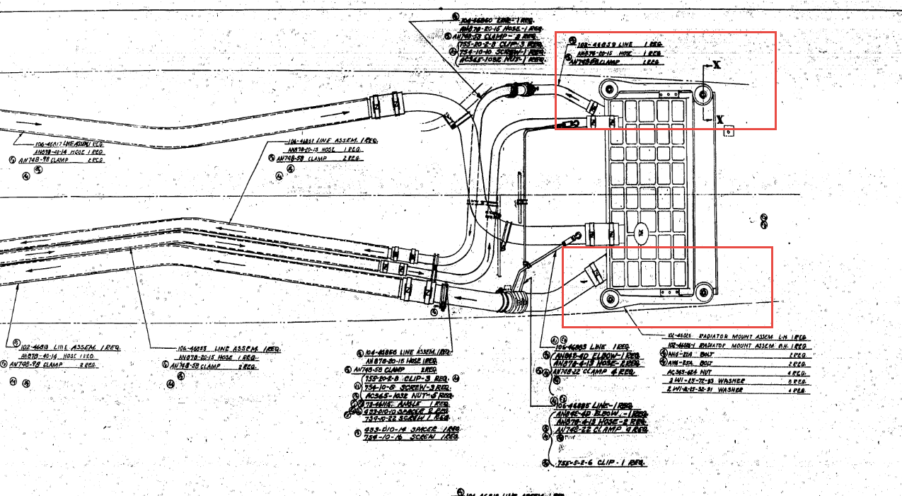
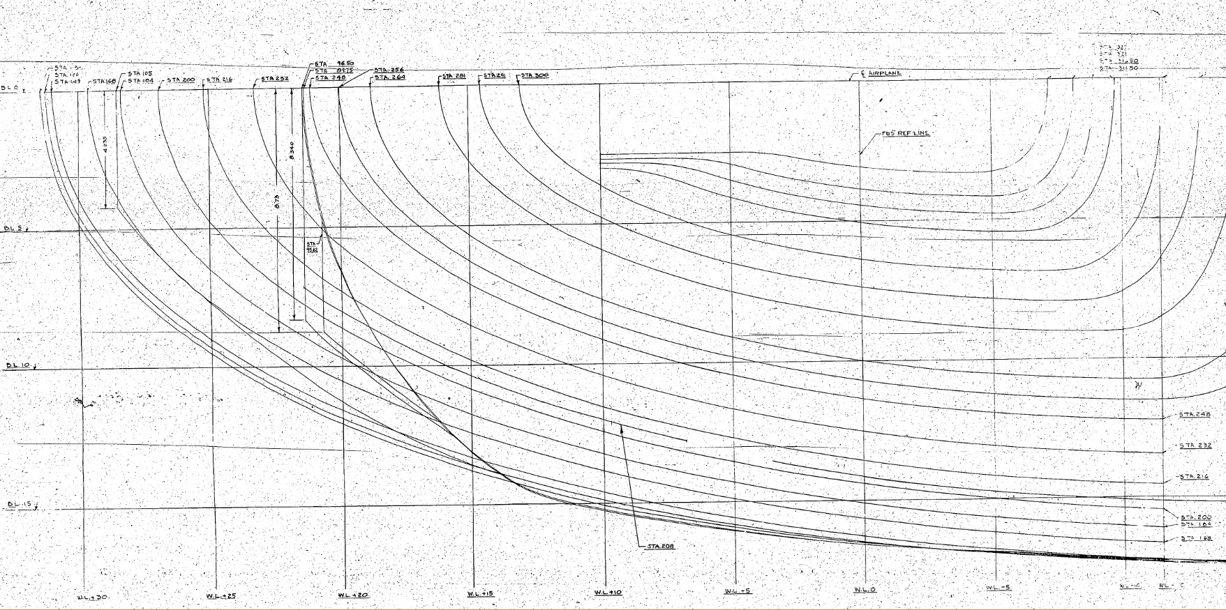
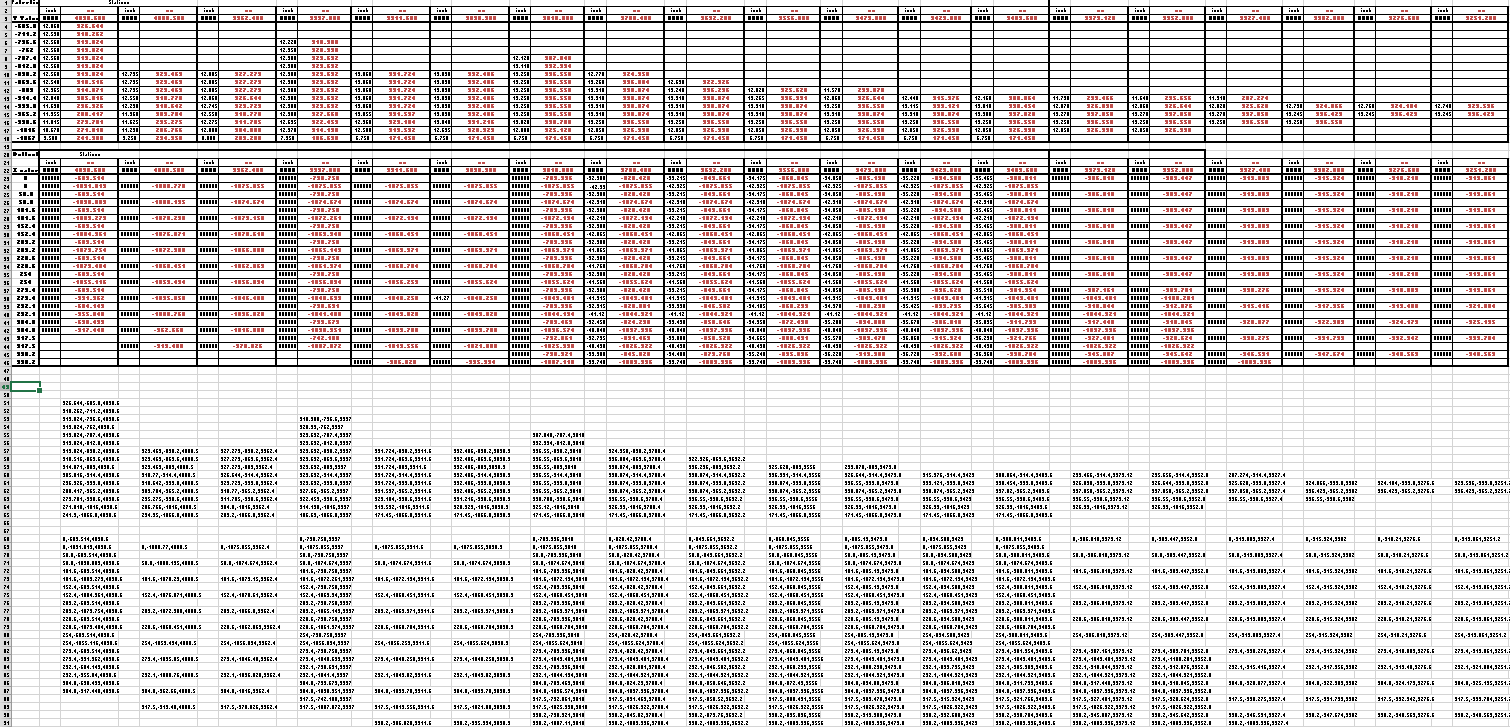
This is a scrap view of the original NAA drawings showing the main ordinates for the Air Scoop.

This drawing shows 2 tables, one of which is the listing for the external contours and the other the internal contours.

The external ordinates comprises a total of 664 points and the internal ordinates comprise a total of 928 ordinate points.

Each point is manually entered into a spreadsheet which lists the Inch dimensions and then converted to Millimeter dimensions.  The data has 3 values for the Station location, the Waterline (value along a horizontal axis relative to the ship ctr line at set intervals) and the Buttock line (value along a vertical axis relative to Frame Ref Line ).

2015-06-04_10-19-41       2015-06-04_10-17-50

These values are then processed using the concatenate function in Excel to extrapolate the required X,Y,Z coordinates.

The points are then grouped and imported into Autocad to derive a point cloud.

2015-06-04_16-57-59 2015-06-04_11-04-09

The first screenshot is all points combined with the local fuselage contours shown for reference; the second screenshot is the internal point cloud. All these points would then be contoured in Autocad to determine suspect locations and any orphaned points.

The external point cloud had 6 points prominently out of sync with everything else which turned out to be an error in the original data set. This is not uncommon and is usually quickly resolved.

Once I have an initial dataset that satisfies these primary requirements I would then import this data into Inventor or Solidworks for evaluation as a surface in each case.

At this stage, I have spent about 3 days on the data preparation and would expect to spend at least a week to properly evaluate the surface definitions.

It can be very satisfying work when you see for the first time all these data points translated into something tangible as a 3D model depicting the end product first realized all those decades ago.

Update: Decided to pull out all the stops and complete the datasets and point clouds: