NAA P-51D Mustang: Fuselage Lines; Polynomials.
This evening I spent some time looking back through some old notes I had on fuselage design, particularly Conic sections and Setting-out design theory.
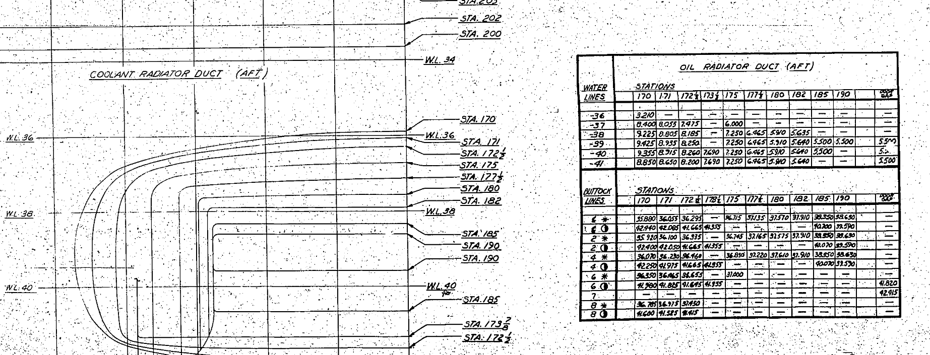
Checking through the archives for the Mustang P-51 we have a design set for the wind tunnel model with a line plan showing the Shoulder Points (SP) and the “point of convergence” where the upper line of the Mustang fuselage converges with the lower fuselage line and the Fuselage reference line.
 The Wind Tunnel drawings are a quarter scale but are quite accurate.
Here we can see the “point of convergence” actually defined on the the wind tunnel drawing at the scaled sta 92. Technically station 92 does not exist as it is outwith the fabric of the WT aircraft, but for convenience I have defined it!
So with this in mind I decided to undertake an experiment to calculate the “point of convergence” with the fuselage ref line according to the manufactured ordinates.
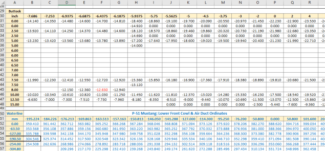
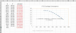 For this exercise I used the upper line of the fuselage, shown here as X,Y values starting from Station 113 and created a line chart.
I applied an third order polynomial equation to the line chart with a scientific value to 5 decimal places to increase the accuracy.
I recalculated the values of the Y ordinate to check that the formula produced an accurate result; shown in red. As you can see the resulting values are very close to the original Y values.
The last X value is the projected value I want to calculate to achieve a “close to zero” Y coordinate thus by definition being the calculated “point of convergence”. This value is 9518mm (374.725 inches) which compares quite well with the Wind Tunnel drawings showing this to be 92*4=368 inches.
Should I recreate this exercise but instead use a fifth or sixth order polynomial equation I am quite sure the resulting value for the point of convergence would be closer yet to the scaled up wind tunnel value.
Normally for this type of exercise I would work with tangent lines and the start points of the upper and lower fuselage lines from predefined Shoulder Points.
This was a bit of fun just to demonstrate how we can use the power of spreadsheets and mathematical equations to assist with developing our Cad designs.
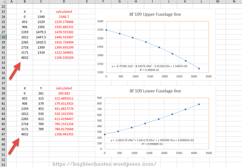
 Update: I decided to play about with this a bit more and had a look at the fuselage lines for the Bf109. I don’t have the design “point of convergence” for comparison but decided to do it anyway to find the convergence between the Lower and Upper fuselage lines.
These points are measured from a ground datum at 800mm below the fuselage reference line.
The stations/frames are from 2 – 8 inclusive. As you can see the calculated values verify the existing ordinate dimensions with the projected “point of convergence” calculated at 4832mm from station/frame 2.
These are the fuselage lines on the vertical plane which in theory should share the same convergence point for the fuselage lines on the horizontal plane (technically plan of max width)…an exercise for some other time!
What is even more interesting is that a line equation can be used to generate a spline in both the Inventor & Solidworks cad products… as a check to verify the cad work this is enormously useful!
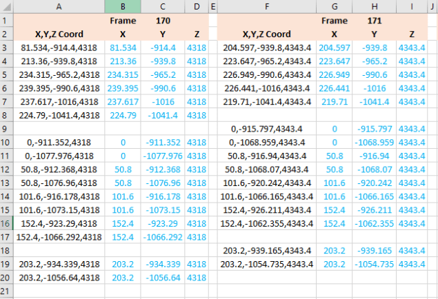
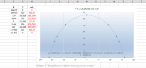 Another example of application would be for the frames or station profiles.
In this example I have applied a polynomial equation to a set of ordinates for the top section of station 300 for the P-51 Mustang.
This needs a full profile as an arc to achieve an accurate result, which I’ve applied as a sixth order polynomial…you cant get much more accurate than this with Excel!
Ideally we would wish to extend this arc to the max width ordinate, which would add another negative ordinate (below the base line) to the graph…for some unknown reason Excel finds it difficult to compute an acceptable polynomial with 2 sets of negative values, so I would have to transpose the ordinates accordingly.
The Mustang ordinates induce a minuscule negative curvature on the top rear fuselage frames when you create a CAD profile just using the ordinate values from the NAA drawings. Its not detrimental in anyway but it is rather annoying…so to obviate these issues I could utilize a polynomial solution to adjust the ordinates to get a positive curvature. The adjustment is micro millimeters, but hey that’s the way that CAD works.
 Another Update: Out of curiosity I recalculated; to a higher degree of accuracy; the upper fuselage line for the P-51 and contrasted that with a similar calculation for the lower line of the fuselage.
The calculated point of convergence of both lines based on a 4th order polynomial to 5 decimal places is at 9375mm and slightly above the fuselage reference line at +18mm. Factoring in error based on the original ordinates being accurate to 1/16th inch and possible error as a consequence of a higher order polynomial I think this is a reasonable result. Its interesting to note the variation with the results we got before.
This is certainly closer to the expected values based on the wind tunnel data. The squiggly line by the way on the lower part of the fuselage is the plotted max half breadths; which is rather interesting!
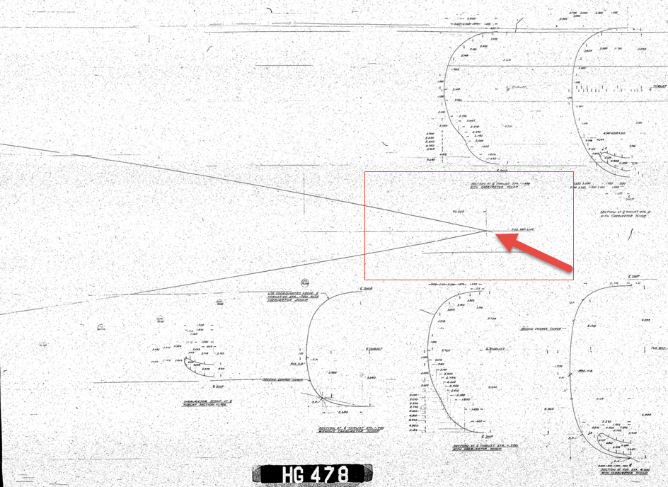
Confirmation; have received confirmation that the intended point of convergence for the upper and lower fuselage lines is at Sta 368, which is at 9347.2mm…this is great!!
All CAD profiles included in the P-51 Mustang Ordinate Package now available. Refer promotion here.


 For use in Cad systems like Autocad, it is recommended to collate these in a TXT file by simply copying and pasting.
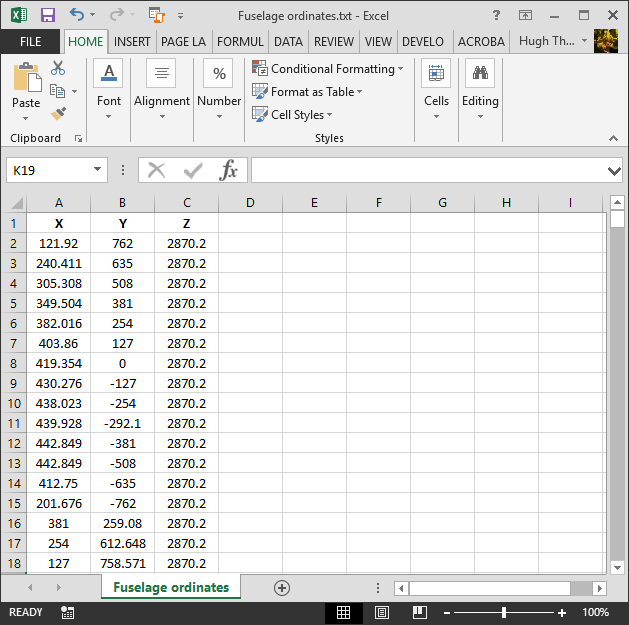


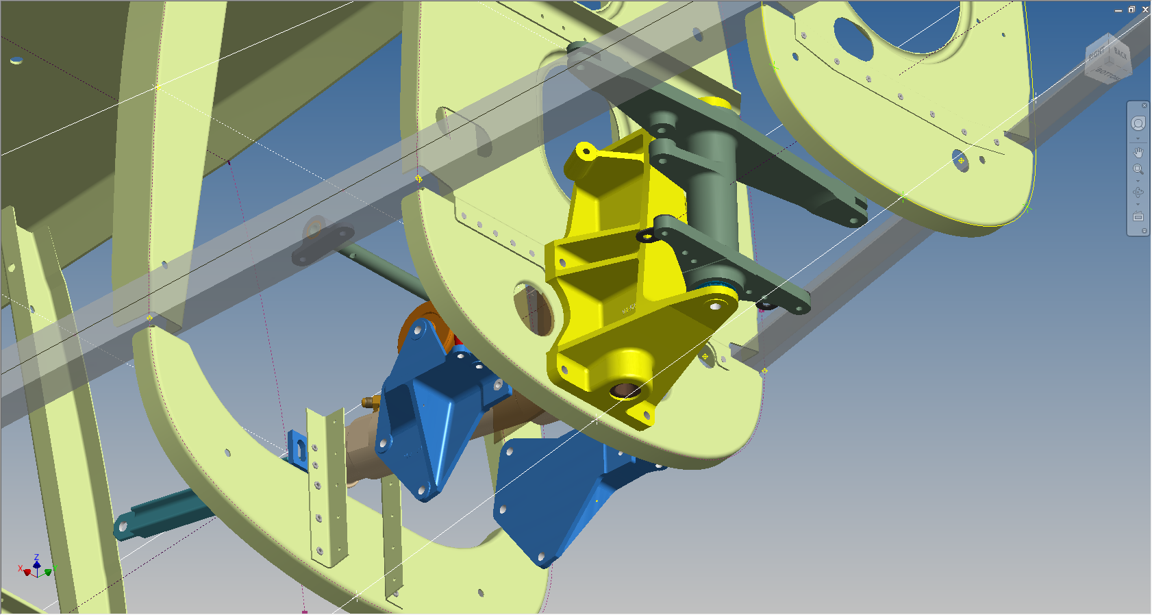
 102-00005: Fuselage (BC main)