Technote: P-51 and P-39 Standards

Technote: P-51 and P-39 Standards

During the development cycle of any aircraft the manufacturing standards tend to evolve and commonly change content, description and name. Keeping track of those changes is key to ensuring the defined parts are correct for the assembly of components.

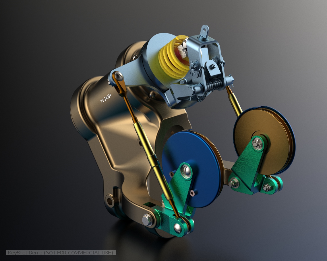
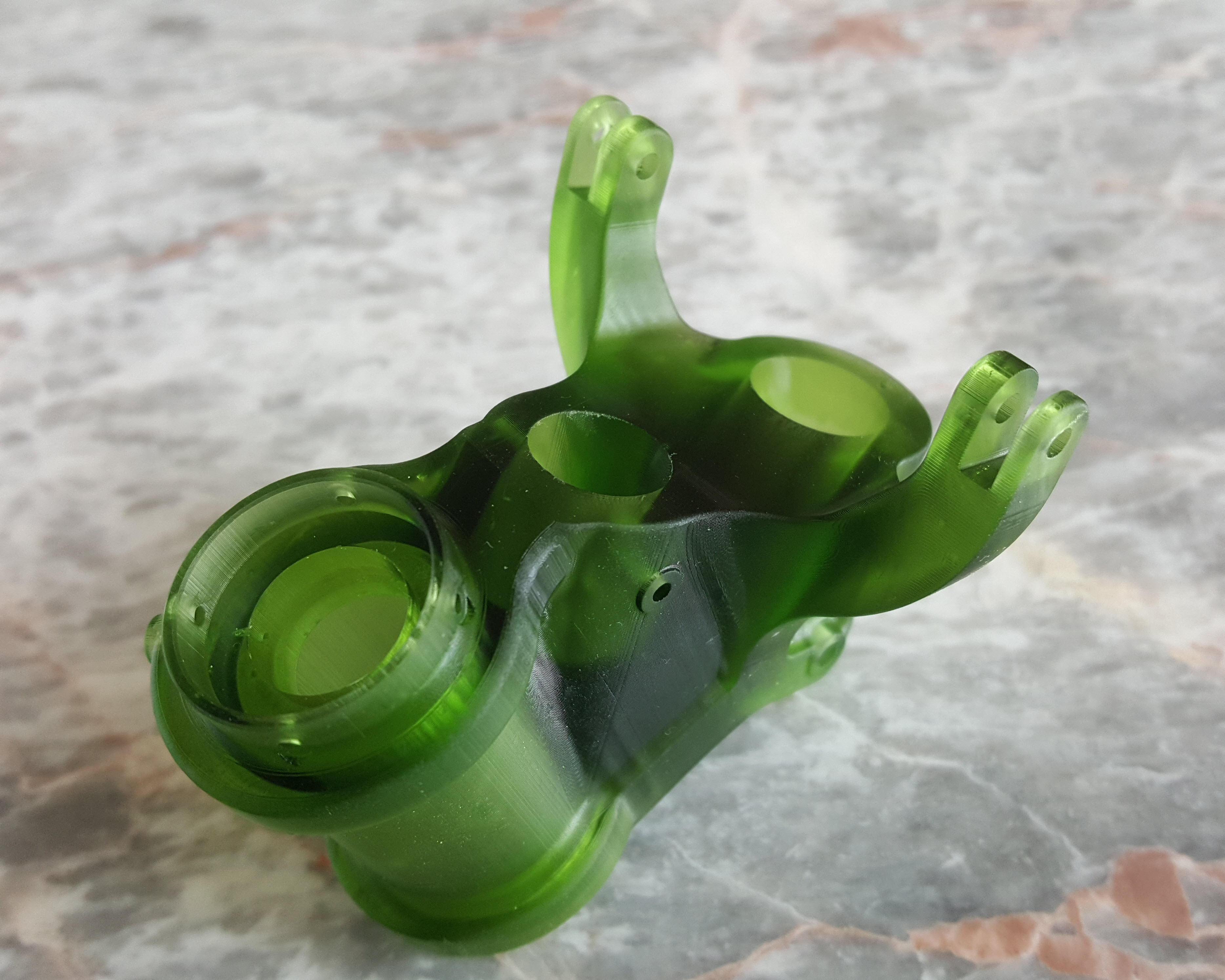
Alongside the P-39 Restoration project, I still develop several aircraft components for other aircraft. This includes my old favourite, the P-51 Mustang. This example refers to the Quadrant Assembly for Engine Control; drawing #102-43005 for the early P-51B.

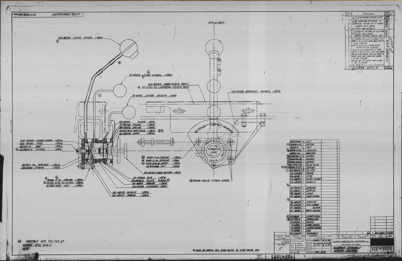
Many of the standard parts called up on this assembly use the early standard references. These are typically prefixed with “B”, like B1009, B1135, etc. These standards were later updated, and a new series of standards replaced them. I have correlated these in a spreadsheet, as shown below.

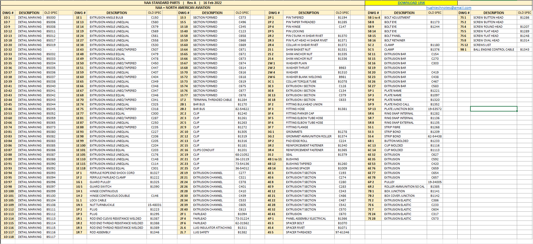
The spreadsheet only lists the standards that are available in the blueprint archive and may not be a complete record. For a more comprehensive listing, refer to the Erection and Maintenance instructions for the P-51A series (T.O. No. 01-60JC-2). Check the Conversion lists from pages 404 onward.

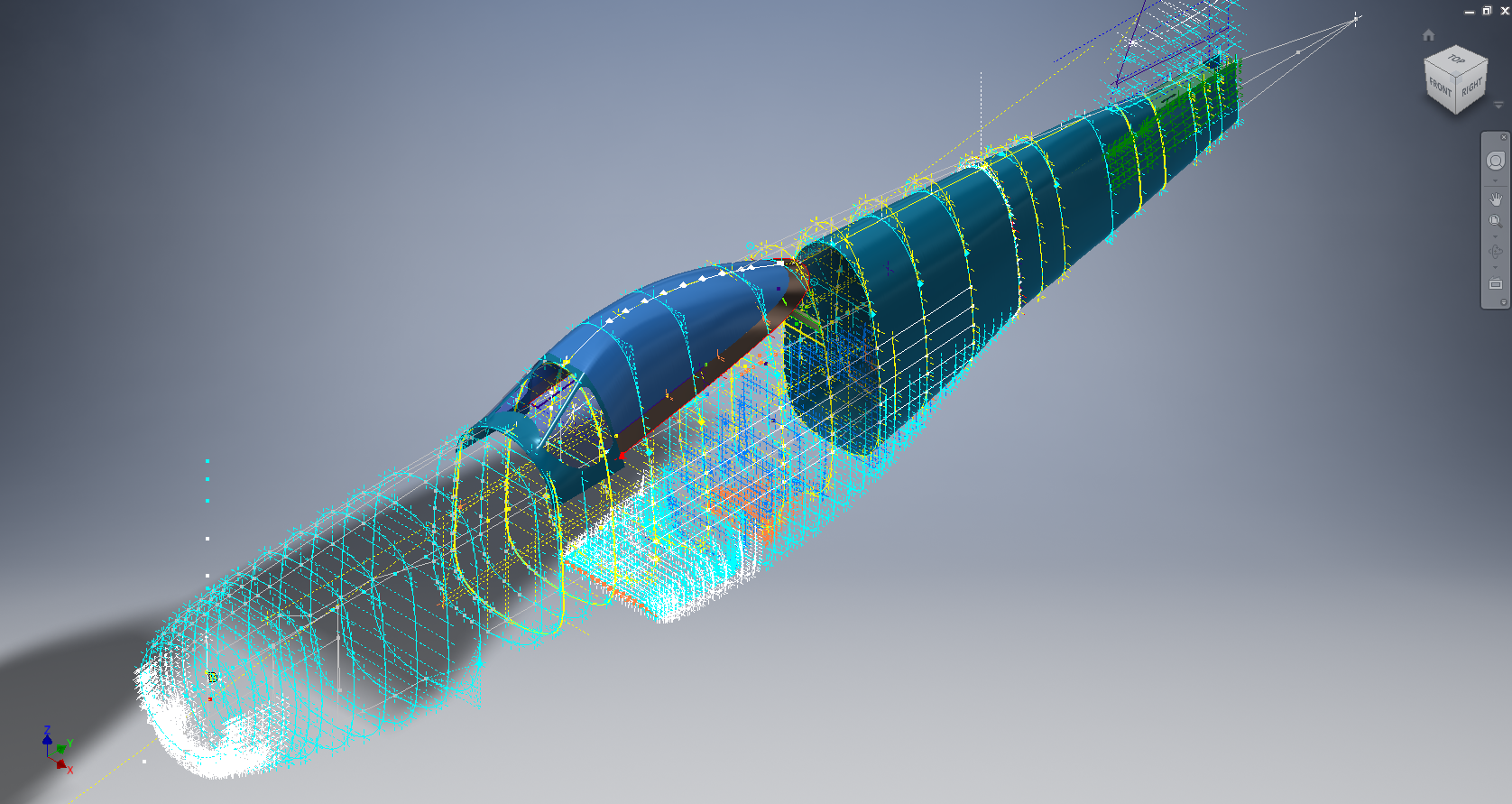
The CAD development of the Quadrant Engine Control is still a work in progress…created to the exact original dimensions.

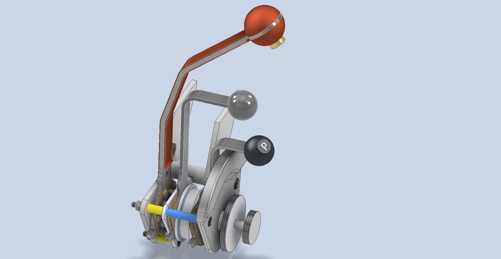
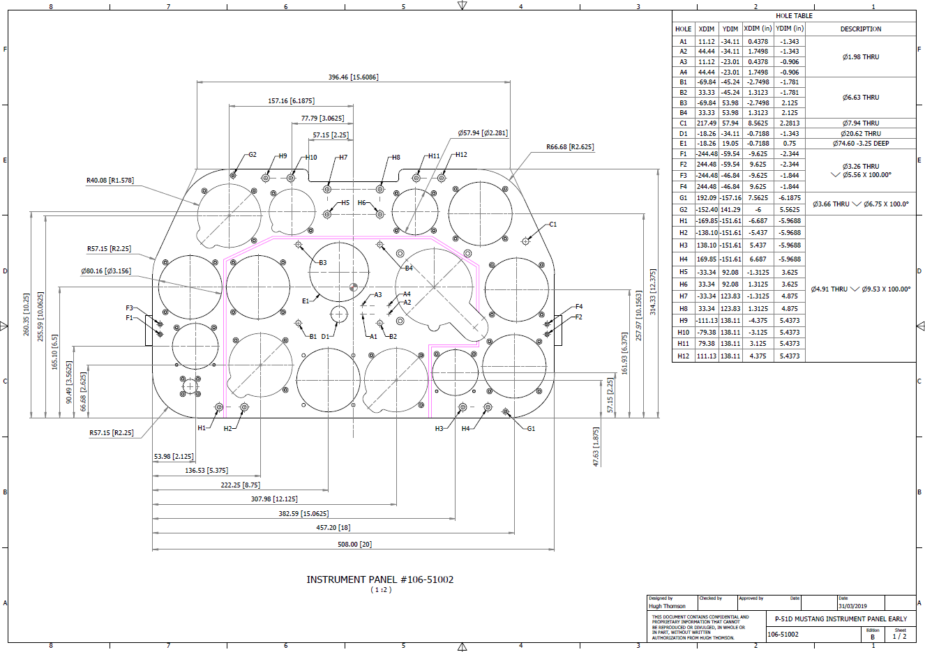
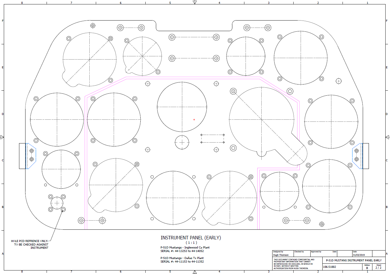
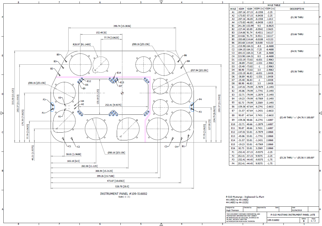
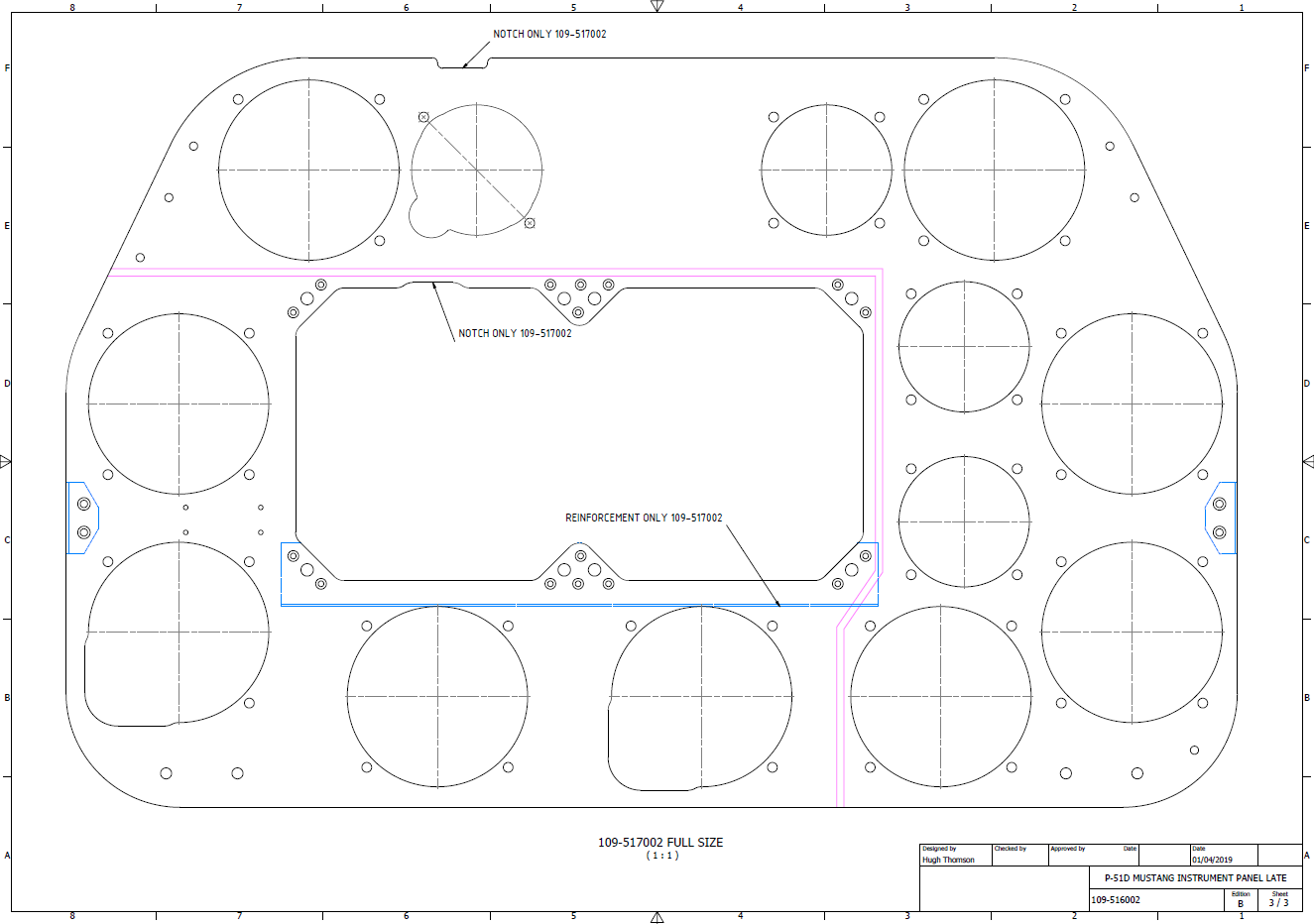
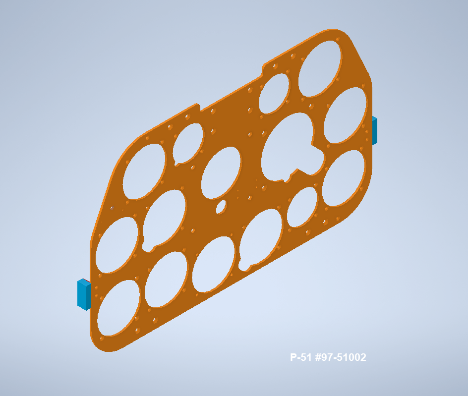
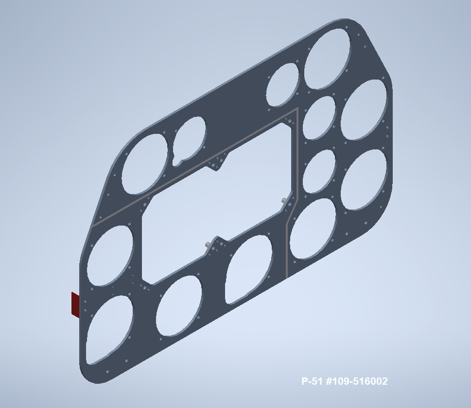
My plan for the P-51 is to further develop the instrumentation for the early and later versions.

P-39 Update and Standards:

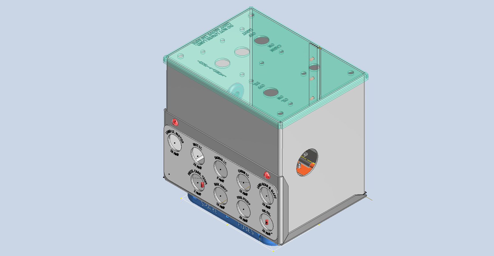
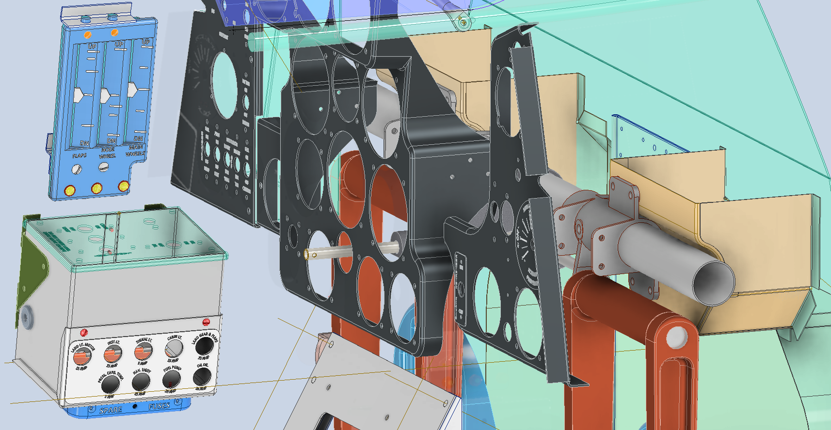
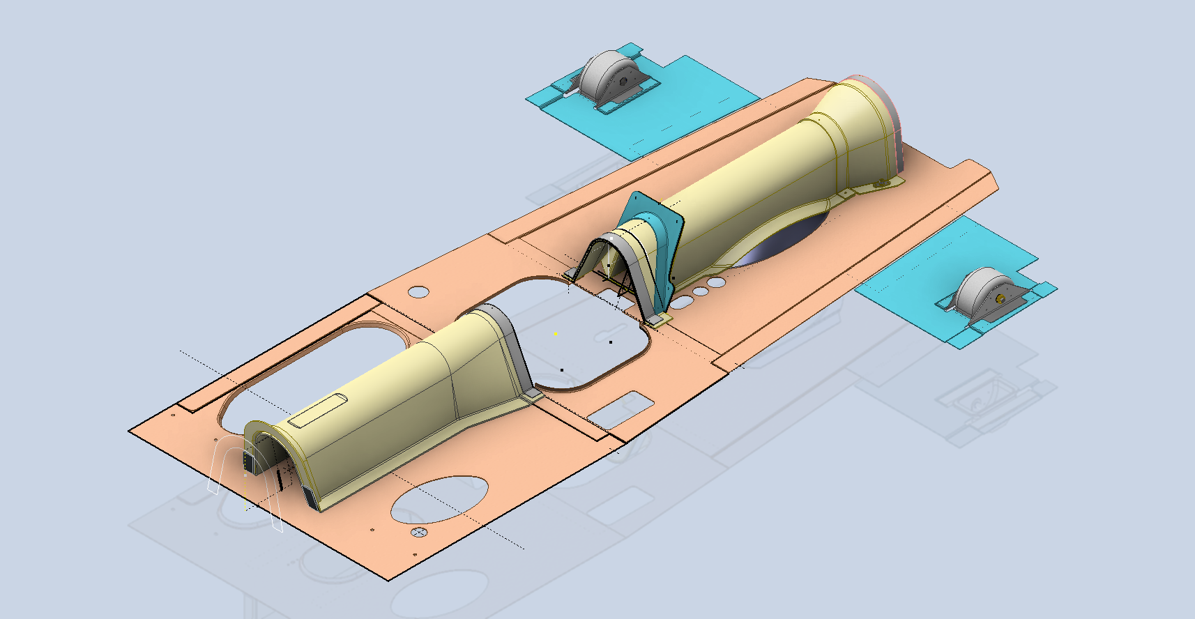
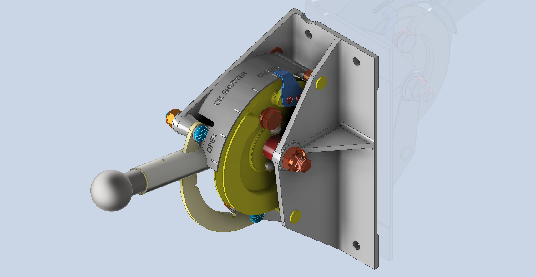
Over the last few months, the P-39N Restoration project has been my primary focus. We are close to completing the CAD work for the Cockpit instrumentation.

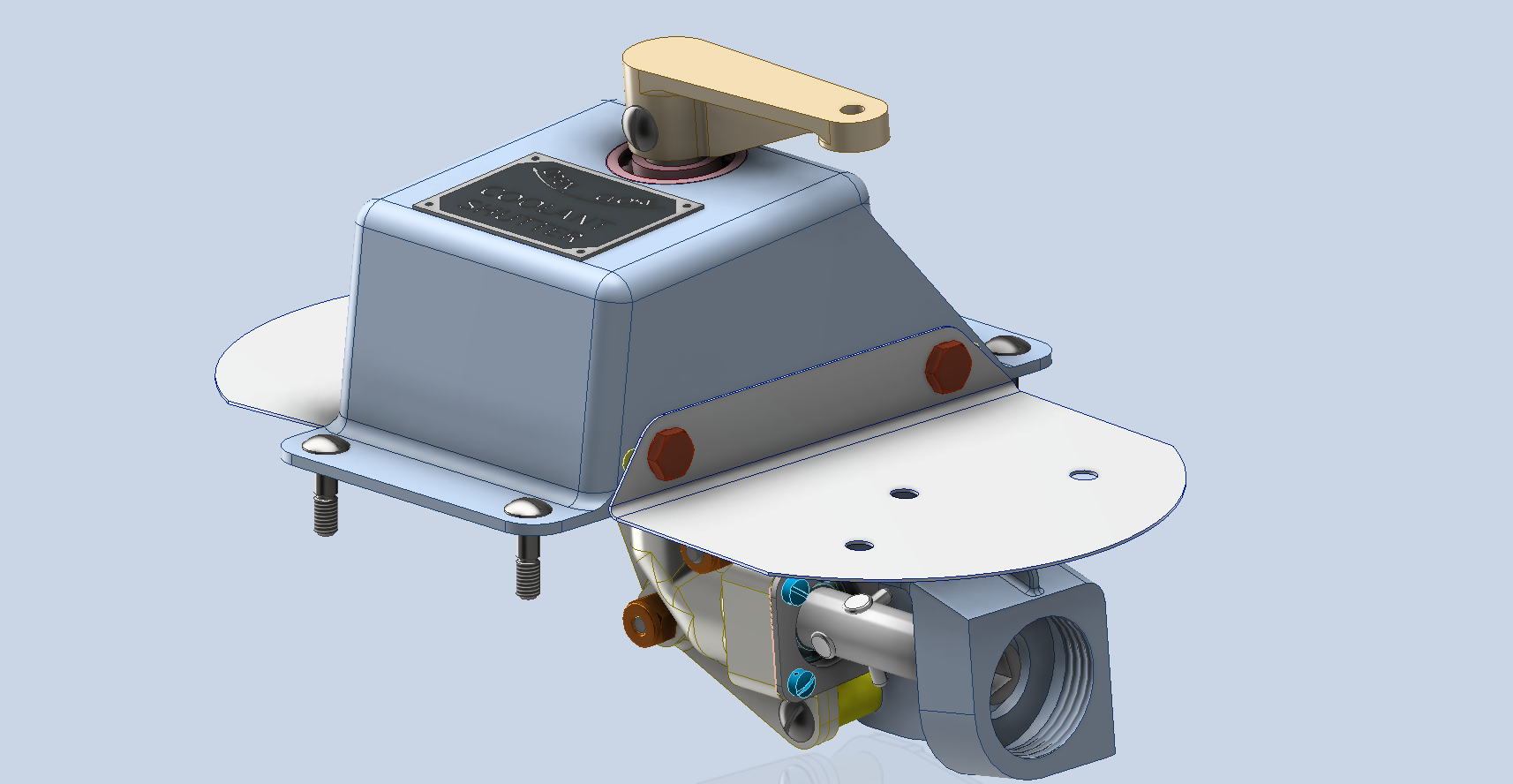
By contrast to the P-51 Mustang, we don’t have the same collection of Bell Standard part blueprints. We only have what is available within the manuals. However, the notations for the parts are similar for the industry as a whole. For example, a Spacer Part noted as Q065-6-20 shares the same notation for the dash numbers as the P-51 (standards 4s3 and 4S4). This in turn will define the spacer size…the first dash number sequence indicates the bolt size and the second is the length. In this case, it would be #6 bolt size. The length is defined in 1/32nd inch, making it 20/32″ (5/8″) long. This table derived from the iPart feature explains the designations in more detail.

The next time you come across a part reference you are unsure about, cross-reference it with other aircraft-known standards. Also, consult the comprehensive collection of AN and MS standards on Everyspec.com.

P-51D Mustang: 3D Instrument Panels

P-51D Mustang: 3D Instrument Panels: Updated 11 June 2022

P-51 B and D Instrumentation Panels are now available online as a separate package. This package includes all below noted Instrumentation Panels 3D CAD models in STP, STL and 3D DWG formats with associated dimensioned 2D drawings and PDFs. Note the hole positions are listed in a tabulated form on the drawings which can be extracted for CNC work.

Also included is a copy of the original NAA instrumentation drawings for reference.

Update 20th June 2022: All Instrument panels now also include the Parasolid X_T format. The complete package is available for download, get in touch at hughtechnotes@gmail.com.

Early Version P51D: 106-51002

Later Versions: 109-516002, 109-517002

Update 15th Feb 2022

For P-51B Mustang: 97-51002

3D Model Views:

For further information drop me a line at hughtechnotes@gmail.com.

P-51 Mustang: Rear Fuselage Drawing Rev C

P-51 Mustang: Rear Fuselage Drawing Rev C:

The updated revision C version for the rear fuselage and tailfin is now available in the P-51 Mustang CAD/Ordinate package as both a DWG and DXF format.

Incorporates additional curve data, dimensions and general revision.

As usual, all inquiries to hughtechnotes@gmail.com.

3D Printing: P-51 Tailwheel

3D Printing: P-51 Tailwheel:

I’m back after a few months dealing with a difficult period of my life. I would like to take this opportunity to thank those that stepped up to the challenge and supported me through this time.

Many moons ago I developed a series of CAD models for the P-51 Mustang Tailwheel mechanism initially to study the mechanical operations and also to clarify an otherwise obscure area that is not clearly defined on the NAA drawings.

At the beginning of 2021 I had the good fortune to obtain an Elegoo Mars pro 3D printer which just sat in the cupboard until now. Getting my life back on track I unboxed this and setup for my first print which invariably had to be one the many CAD models from my research. The part selected is the Housing for the Tailwheel spindle. Part # 73-34004.

These parts are accurately modeled from the NAA drawings so I was unsure how well they would print at 1:4 scale particularly the thin wall elements.

The first image shows the preparation using the Lychee Slicer program with the layers set to 0.05mm. I added a generous amount of supports to maintain the print integrity using the Auto support feature with a few manually added for good measure. The Resin I used was the Elegoo Water Washable Green which has worked very well. I am rather pleased with this print as I had read many horror stories of problems that folks encountered with this type of immersive printing which made me a tad anxious before I eventually decided to take the plunge.

This printer is capable of printing with a layer height of only 0.02mm which is quite extraordinary but as it took 4 hours to print this model at 0.05mm I doubt if I will venture to printing at a finer pitch as the time would be excessive. I don’t plan to print all the Tailwheel components as my budget for resin is limited but I will print a few more to determine the limitations; if any; of resin 3d printing.

Talking about the future I should note that I am currently sourcing new material for the P-51 Mustang and hopefully to start a brand new project for the F7F Tigercat.

If you are interested in the Tailwheel models check out the bottom section of this post for details.

On a personal note it is good to be back working on these projects and please do not hesitate to comment or drop me a line with any queries. hughtechnotes@gmail.com.

P-51D Mustang: Conic Formula in Excel

P-51D Mustang: Conic Formula in Excel

A quick technote on entering a conic formula in MS Excel spreadsheets. Getting the correct syntax is critical to achieving correct results.

I am updating the ordinate datasheets for the P-51 B/C and D models to incorporate new information using the various conic formula according to the curve type. Typically with these equations, there are a number of constants to be established to input to the final quadratic formula.

excel formula 2

test equation
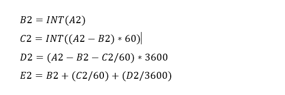
The original formula for one of the constants “P” is given as shown (1). If we enter the formula as prescribed in a hand calculator it will evaluate correctly but will not work correctly in Excel in this format. So we need to tell Excel to essentially divide everything in the top line by everything in the bottom by adding parenthesis as shown (2).

The bottom line shows the actual input in the excel formula bar (3).

We are continually working on updates to the Ordinate and Cad package so watch this space for new articles. There will also be in-depth tutorials on interrogating ordinate information to find max-width, tangents and matched second-degree curves as well as updates on detail drawings.

P-51D Mustang – Instrumentation Panel

P-51D Mustang – Instrumentation Panel

I have recently been working on updates to the Ordinate and Cad package (as noted in the previous posting) and also developing the Instrumentation panel assemblies for the P-51D Mustang.

What started out as a mere curiosity is actually turning out to be a fairly intensive project requiring a lot of research.

For the P-51D there are at least 4 variations on the main instrumentation panel for the early and late models. The U-shaped Support frame has 4 variations and just as many for the lower instruments panel set at 20 degrees to the main panel. It is important to get the correct combination of components for the various model numbers which is where a lot of my time is spent on the research.

Part of that research is, of course, getting the label text just right which is where I encountered a lot of frustration. The generic text font used on the Mustang and many of the contemporary aircraft at that time was the MS-33558. There is a TTF font available online for download but the design is not very good with problems of self-intersecting edges and spacing definition.

Military-Standard-MS33558ASG
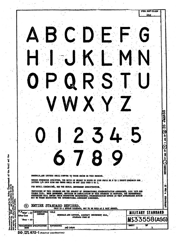
Using this font in CAD systems will result in problems with embossing or extruding.

Typically I had to find out why, so I downloaded a copy of Fontforge to analyze the characters and identify the problems. Most of the characters are fine but there are at least 7 that have intersecting line problems. However, due to the nature of the font construction process, it is very difficult to identify the problem areas and thereby to devise a solution.

I spent a few hours looking into this but font development is a relatively new procedure for me and I did not achieve any satisfactory results. This I think needs an expert touch. I appreciate the work that was done in developing this TTF but please whoever designed it just a bit more attention to detail would have saved me a lot of work.

In the interim, I decided to use the closest font I could find on my system which was a default SolidEdge font that is similar in style. I had SolidEdge as a trial program a while back and thankfully it left the fonts behind when I uninstalled it.

Another small point worth noting is the color of the label text. The images above show the early P-51D version arrangement and you will notice in the bottom left corner of the first image is a selection of text in red. It is “EMERGENCY” with an associated note. The drawing states that this is RED on a black background but many of the photos I have seen of this particular version show the text in white. So the question is did NAA change this at some stage or is it just down to restorers’ preference?

P-51 Ordinate & CAD

P-51 Ordinate & CAD Package: 

A comprehensive overview of the Ordinate/CAD package for the P-51 Mustang B,C and D aircraft. This package is the result of over 2 years of extensive research and development incorporating everything I know about the ordinate information pertinent to the P-51 Mustang; now available for download.

Fully Dimensioned Layout Drawings (Autocad 2d):

These are my CAD files that you can use for your own projects. These files are being made available for personal use only and not for commercial gain. Detailed layouts, fully dimensioned.

51j

engine mount revb

Tip 1: The Engine Mount drawing is a good starting point when setting out your CAD model. This will establish the fuselage datum points, Thrust line, Engine mount locations, and Firewall.

The dimensions for this have been triple checked. Incorporates information extrapolated from 6 different documents.

Tip2: Did you know you can work with inch and mm dimensions in the same model. If you happen to be using an mm template and wish to input inch dimensions then just type in the value followed by the unit type; either or in. So for 1 3/8in enter exactly as shown including space and vice versa if working in the inch template and using mm just quote mm units.

Over 228 Autocad 2D Point Profiles Derived from Spreadsheets:

These are my CAD files (DWG) that you can use for your own projects incorporating the point data. These files are being made available for personal use only and not for commercial gain. 2D profiles of all frames for wings and fuselage.Ordinate DWG profile

Ordinate Spreadsheets: 1000’s of Ordinate Point Coordinates (mm and inch):

These are my Excel spreadsheet files that you can use for your own projects. These files are being made available for personal use only and not for commercial gain. All ordinate points painstakingly entered by hand in both mm and inches. Data is sorted and extrapolated to derive 3d coordinates for direct input into most CAD systems.

Original Military Specs AN & MS (fair share) with Dimension Spreadsheets:

Standard specifications and dimensions for parts including turnbuckles, bolts, nuts washers etc. 3D CAD models of these parts are available separately as a collection; refer to the CAD library tab. Relevant parameters are recorded in spreadsheets that can link to CAD models.

2019-10-06_17-03-01The full Ordinate/CAD dataset will literally save you 100’s of hours of tedious work and is available online. For further information please send an email to hughtechnotes@gmail.com 

This Ordinate/CAD dataset is only available from my blog. All work and research were done by me. All spreadsheets and DWG files are fully editable.

Models on CGTrader:

Alongside the ordinate and dimensional research I also have a large number of professionally prepared 3D CAD models for the P-51 Mustang now available for download on CGTrader.These include the Tailwheel assembly for the P-51 Mustang. All parts, including all internal components, nuts, bolts, washers, and pins modeled to original standards. Tailwheel CAD assemblies on CgTrader:

P-51 Mustang TW Shock

exit These CAD models include fully itemized layouts for each assembly.se

As usual please get in touch at the following address for all inquires HughTechnotes@gmail.com 

NAA P-51D Mustang: Landing Gear Dims

NAA P-51D Mustang: Landing Gear Dims

I am currently working on the Landing Gear geometry dimensions to check the data for accuracy. During the course of this research, I thought it may be of interest to share some Excel formula for converting angles shown in Deg Min Sec to decimal degrees and vice versa.

p-51 Landing Gear

The plan angle for the OLEO Strut relative to 25% wing chord is 4° 32′ 35.14″ as shown in the above sketch which translates to 4.543094 degrees.

The accuracy of the angles and dimensions in the NAA documentation is rather good with small deviations occurring of only 0.003mm when developing this in CAD. I should note this deviation is negligible and for all intents and purposes can be ignored. However, I like to get this stuff right so I have set about developing the landing gear dimensions to be as close as possible to be exact.

As I have already developed the cad geometry I measured the same angle above from the CAD system which is now giving me 4.54309673 degrees.

In Excel:

excel table

Starting from the left; in column A; I have input the angle from the cad system, then systematically converted to Deg, Min, Sec in separate cells and then converted back to a decimal angle in column E.

The equations for each cell are as shown below:

p51 Landing gear eq

Just enter the equation in the cells denoted; so for the first equation, this would be in cell B2. The latter equation works fine without parenthesis, which I included just to keep the equation tidy.

The Landing gear geometry will be recorded in a separate spreadsheet and added to the P-51 Ordinate Package. Mustang P-51 Ordinates

P-51D LG

NAA P-51D Mustang: Front Fuselage

NAA P-51D Mustang: Front Fuselage

Following a recent inquiry, I have revisited the NAA P-51 Mustang project to develop the front fuselage and cockpit. This will be an extremely detailed and accurate model including fixings and rivet holes.

P-51D Early.png

The partial structure above is for the early P-51D version; note the instrument panel and support frame. There are also some minor differences with the other components, most notably the curved beam which has different end brackets for the early and late versions.

The 2 instrument panels depicting the P-51D versions, with the later version on the right. This will be a medium to long term project for which I will post regular updates.

NAA P-51D: Master Lines Plan

NAA P-51D Mustang: Master Lines Plan

The P-51D project is progressing well with further developments on the fuselage frame profiles. I now have a comprehensive Master Lines Plan incorporating additional information obtained from mathematical analysis, drawings, reference documentation and geometric developments. I have updated and remodeled the underside Oil Cooler Air intakes, canopy, windshield, rear fuselage and fuselage tail-end. As part of the remodel the groups of ordinates for each frame for the Oil Radiator Duct, Coolant radiator Duct and Removable Scoop are now contained on their own respective work-planes. This will make it much easier to micro manage the final mold lines.

Fuselage Master Lines Plan (P-51D overlaid on P-51 B/C):

2017-07-01_14-32-09

Test Lofts and developments:

2017-07-01_14-30-24

Front Views (note the Canopy Profile update from the previous article):


A month ago I was not sure how much could be achieved given the limited amount of information at hand but with due diligence and detailed research, it is quite amazing what can be accomplished.

With this template, it is now technically possible to accurately develop a CAD model for the entire fuselage structure and mechanical components for the P-51D, which would be great; but I often wonder what the value of such an undertaking would achieve, other than being a darn interesting thing to do and a test of CAD modeling skills.

Having achieved this significant milestone the time is right to conclude the work on the Mustang P-51D and P-51 B/C projects. I may continue with the P-39 project but as always I am keen to explore the options for the more obscure extinct aircraft as described in Operation Ark.

2017-07-01_00-15-20

If you are planning on developing your own Master Lines plan a good place to start would be with the 1000’s of ordinates points cataloged and recorded on the spreadsheets here: Mustang P-51B/C Ordinates which also includes the wing ordinates for the P-51D and vertical stabilizer.