Technote: P-39 Airacobra Carb Scoop: New Project:
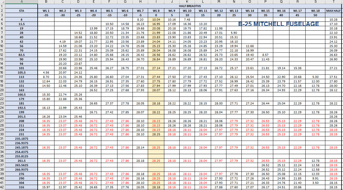
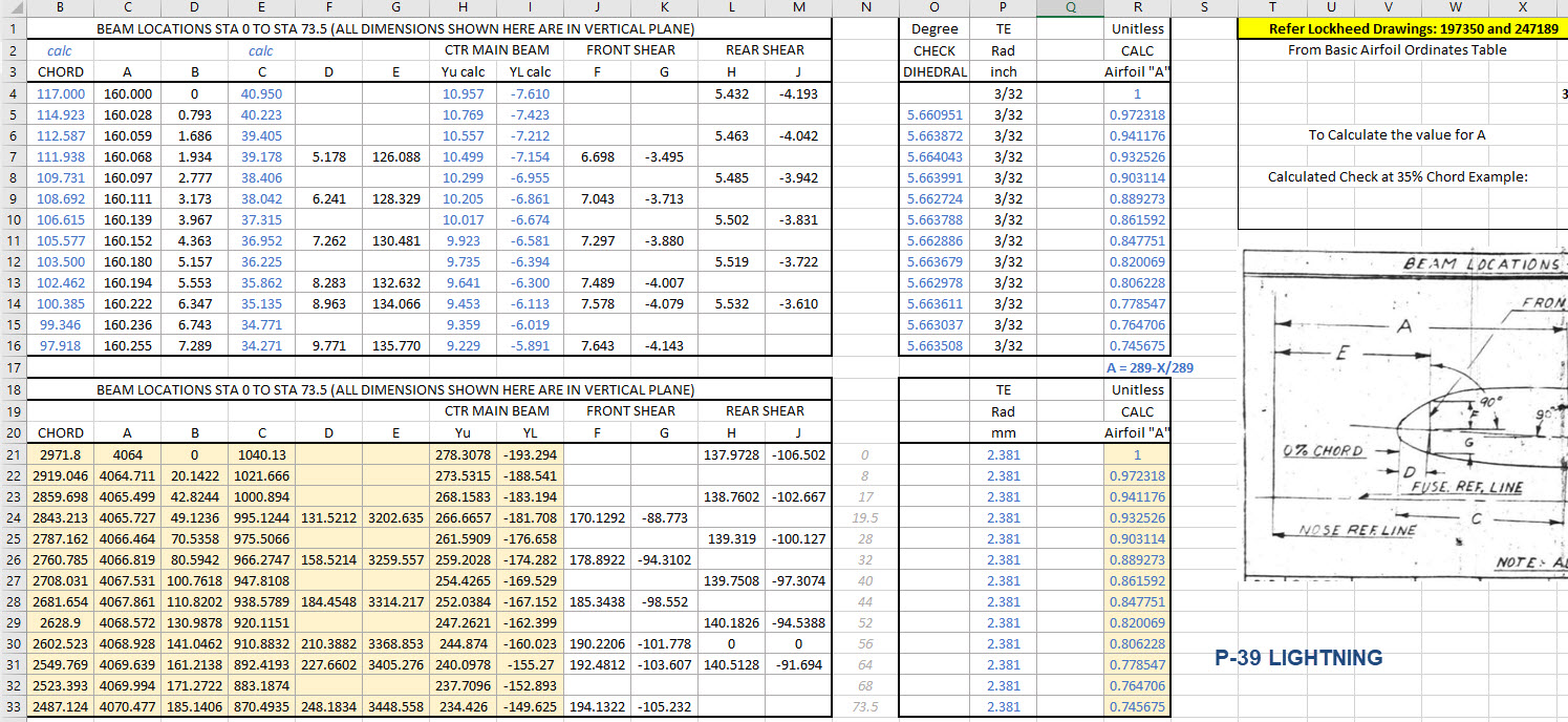
Following a recent inquiry about the P-39 Airacobra, I was asked if I had a model for the P-39 Carburettor Air Scoop. At the time I didn’t, though I did have some preliminary outlines that were done as part of the dimensional ordinate study. So I decided to get stuck in on this new project and see what can be accomplished…by the way did I mention this will be used on a real aircraft. The template moulds will be 3d printed and used to form the aluminium plates.
When you look at a photograph of the Carb Scoop it looks deceivingly uncomplicated however it turns out this part is surprisingly complex. The main body part itself is challenging with the curved profiles and filleted interfaces, the curvature of the fuselage; which by the way is not actually documented anywhere and the transitions from one frame to another to achieve smooth curvature. The internal duct comprises many varying profiles…the profiles tend to be rectangular with different corner radii throughout culminating in what can be described as a slot profile for the Air Scoop inlet.


I have been working on this for a few days now studying various modelling methods to achieve the most accurate and consistent results. So far I have the main scoop body and the fuselage skin modelled. The internal ductwork is set out on a sketch, though I will still have to define a number of intermittent profiles to ensure I get that right as well. Overall there are 12 individual parts for this assembly all detailed on one drawing…so some interpolation of design intent and cross-referencing with a few external drawings is essential.


At the Scoop inlet, there is a small lip that I have yet to model. The drawing has very little information on this so I decided to model the scoop without the Lip and then I will have to sculpt the curved form from extrapolated model information. That Lip at the end of the day will probably look inconsequential but the development work for such a small item cannot be understated. I shall update this article as work progresses.

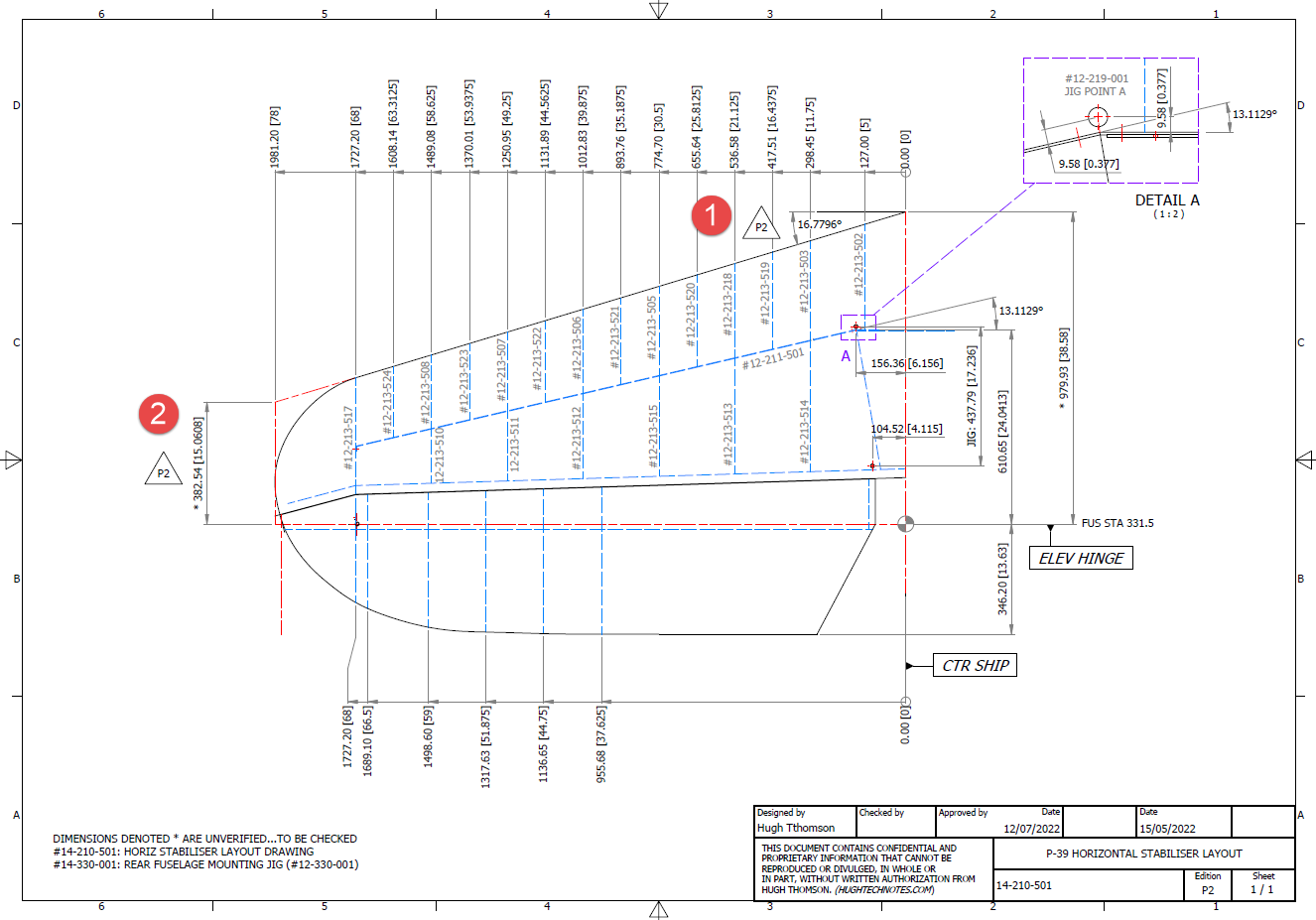
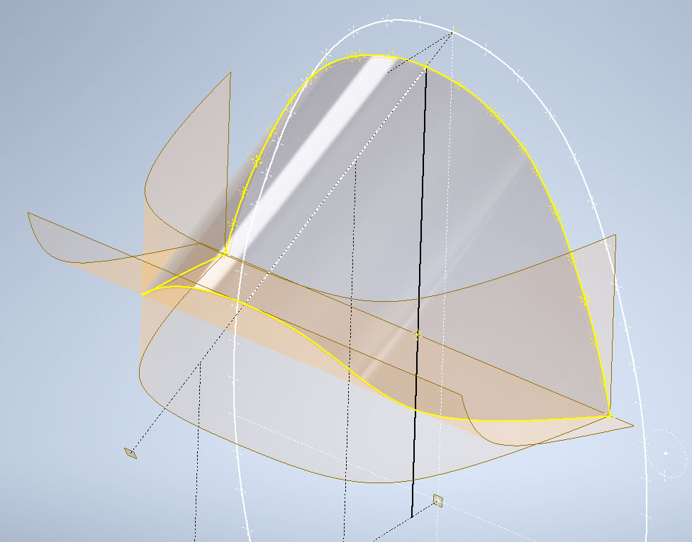
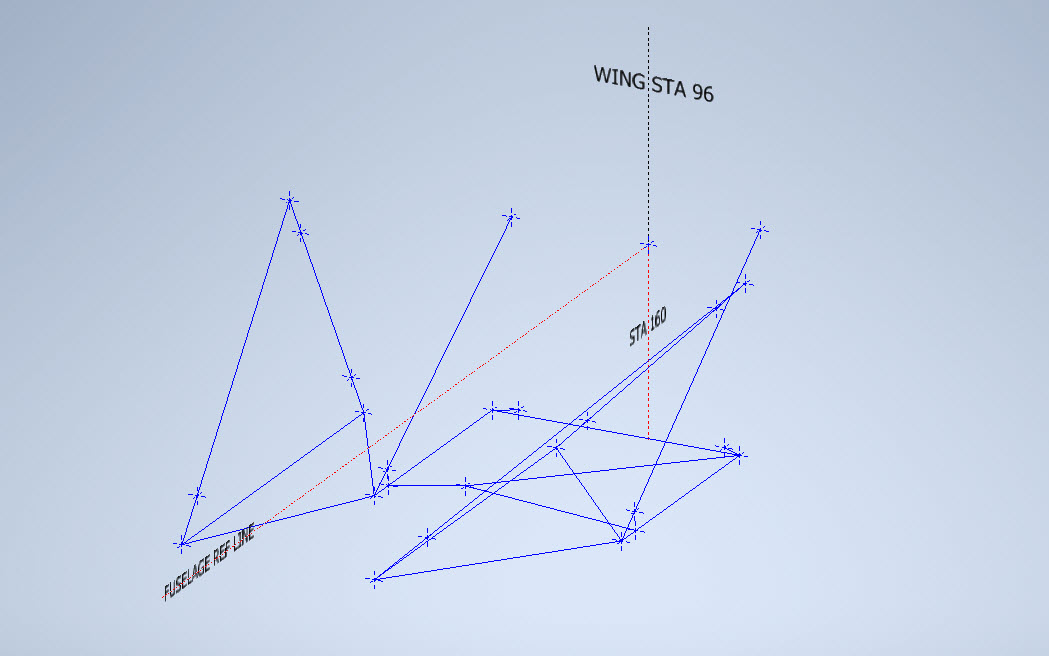
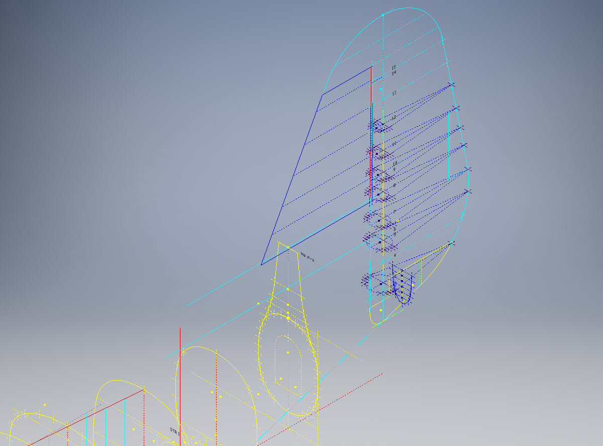
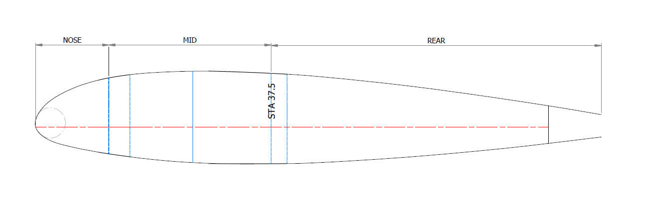
Point “2” is the scoop outline sketches, in which I made continuous elliptical profiles with an additional circular profile at the very tip below the fuselage plate surface.
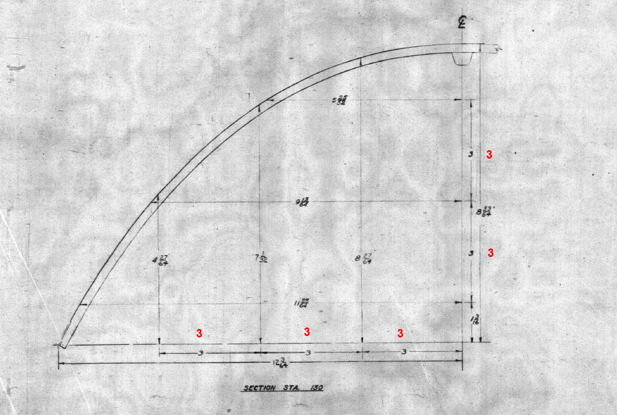
The blue lines at “3” are the lofting guidelines, absolutely essential to getting this right. I initially skimped on this, instead, I attempted to just loft and use G2 or Tangency adjustments…it did not work well…so if you are doing this don’t skimp on these guidelines. Once the scoop body was lofted there was trimming to do with the flange plate (it was the offset from the fuselage surface) and then the 2 items were stitched. This provided an edge to which a variable fillet was applied. Cautionary note on the variable fillet…when initially applied don’t try and create adjustment points all at once…take your time, just create one pair at a time making micro adjustments and let the model regen and repeat.
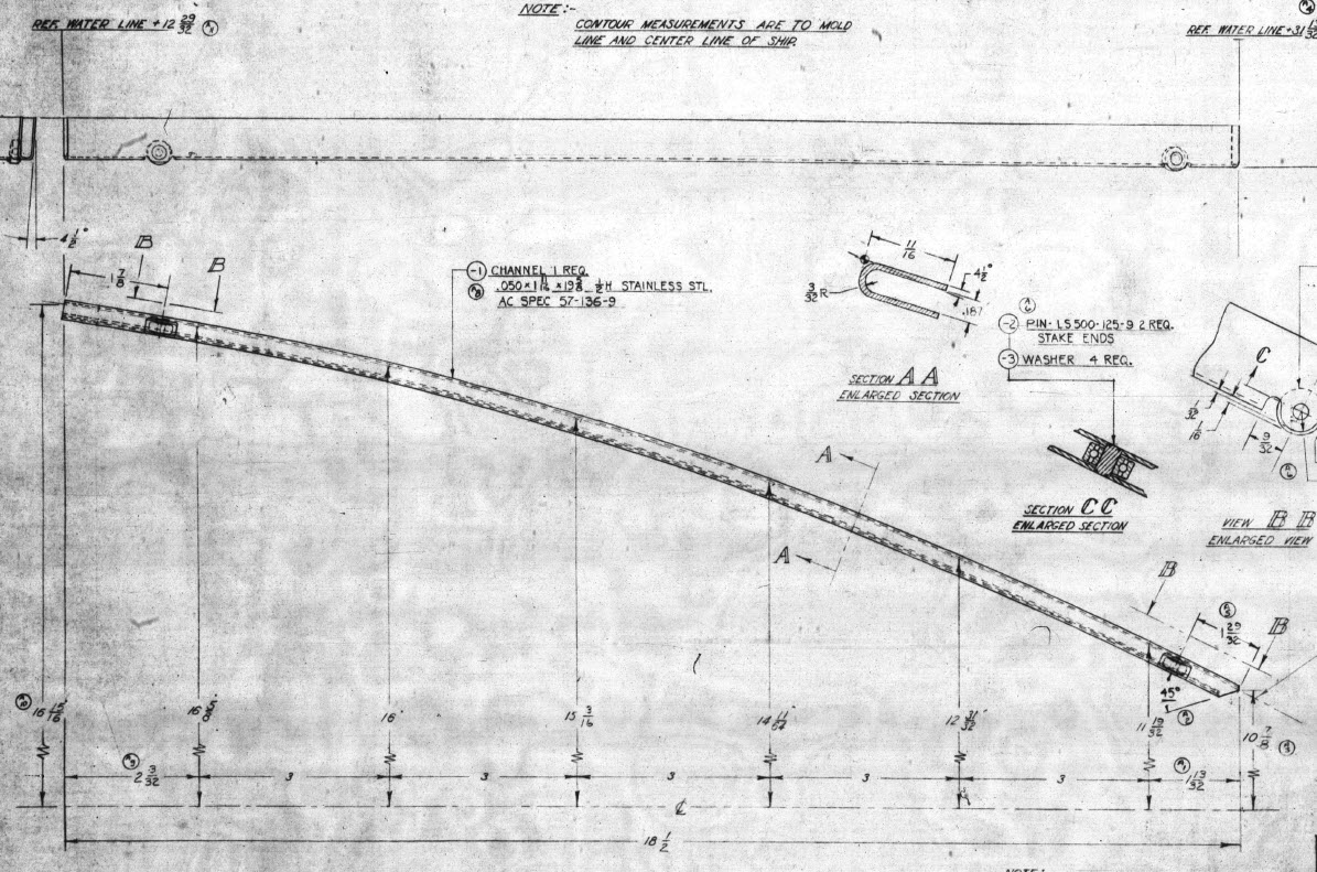
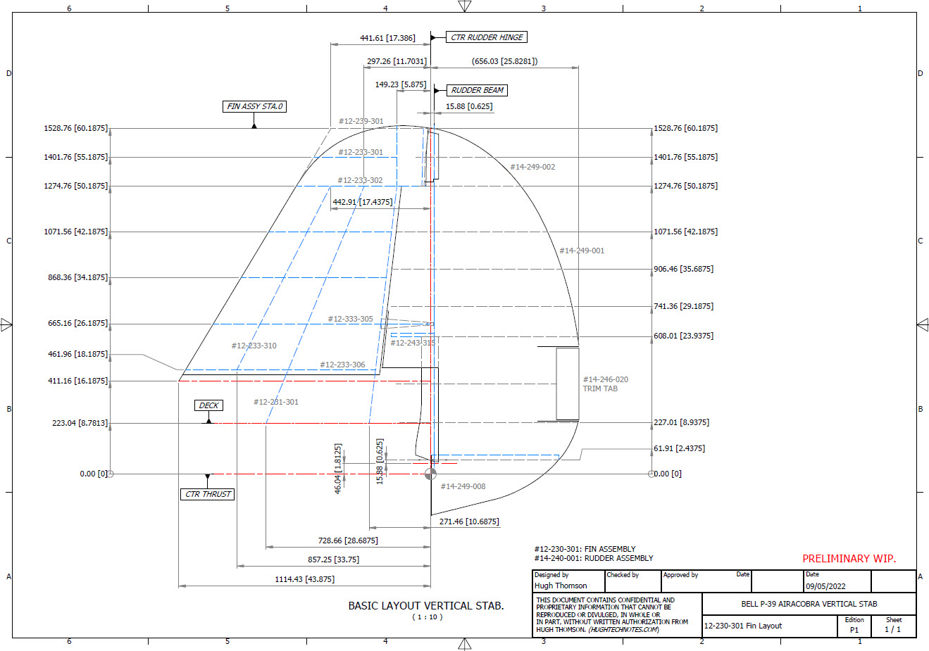
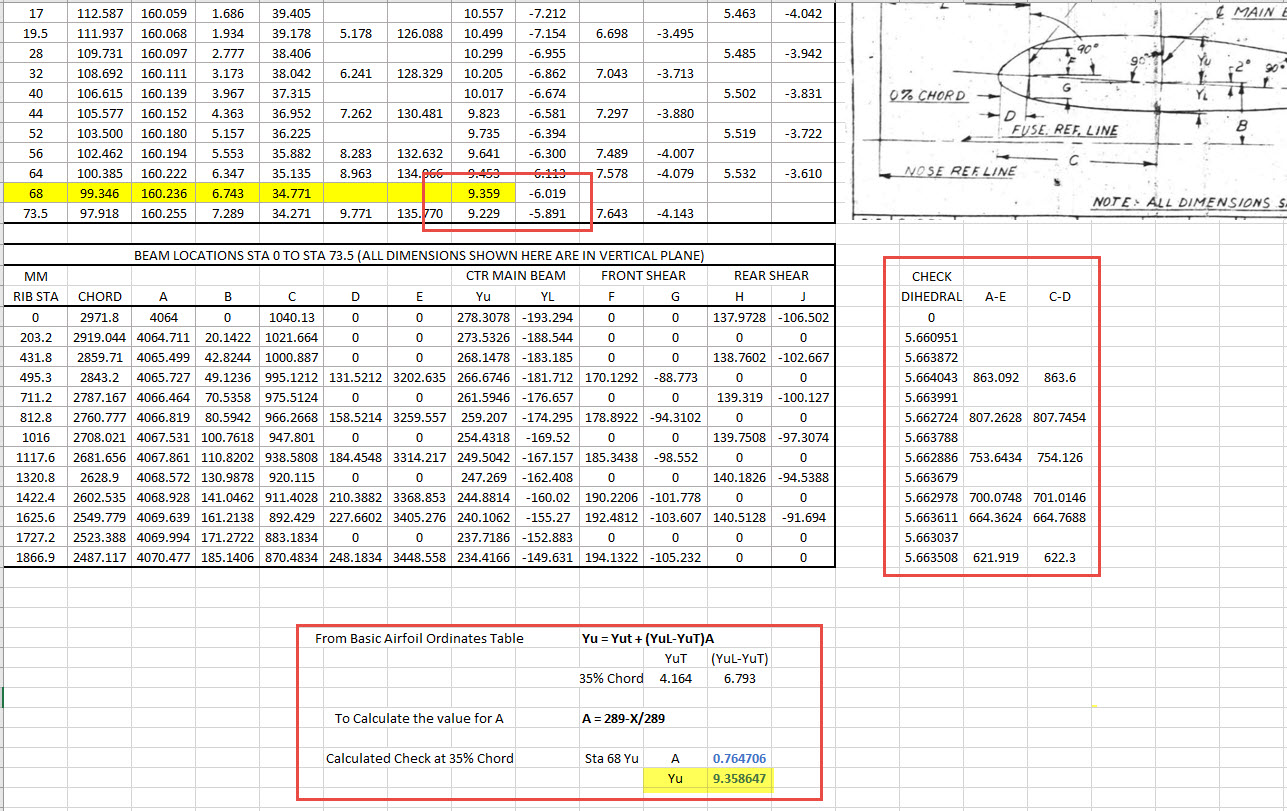
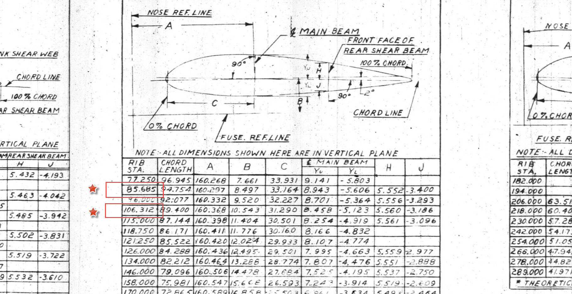
The other key consideration is that the Bell drawing dimensions are generally only accurate to 1/32″ and 1/16″ (0.8mm and 1.6mm respectively). This will invariably impact the eventual quality of the end product when using CAD so it is important to understand where and how you need to compensate.
Update: Internal Duct:
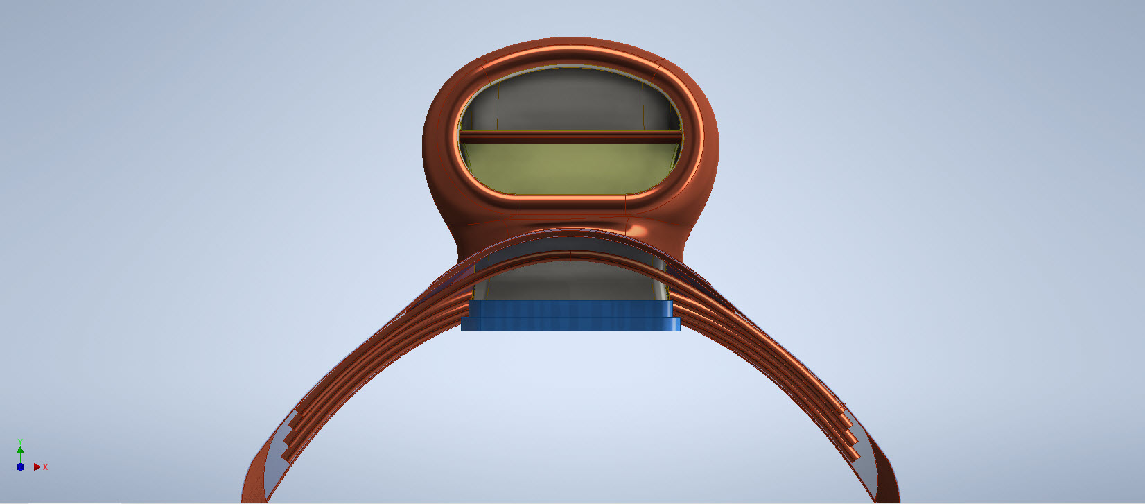
I have now modelled the internal duct which has a partial concave curve on both sides to allow clearance to the main scoop housing. That was a real pain to model and to be honest, to achieve continuity with the duct curvature I simplified it slightly.


The sides of the duct are shown on the Bell drawings as being flat from the base level almost to the scoop inlet itself; merging to a point just past the horizontal breaker bar. I tried various methods of doing this but failed to achieve a good result…even using freeform curves…mathematically it is not to be! I settled for a smooth loft of the various sections to ensure that at the very least I could still achieve the partial concave surface and a smooth shell.
The front curved edge of the scoop inlet has a weld seam which is shown in the centre of the edge on the Bell drawings. I decided to move that joint further inward because an extended flange may reduce the installation clearance when installing the duct.
The curved plate you see will be cut back to finalise the flange for the scoop, which I shall leave until the main parts are all modelled. More updates to follow.
Duct Vane and Scoop Ring Stiffeners:


All inquiries as usual to HughTechnotes@gmail.com
Update 11th Sept 2022: Almost There:
Looking good and is deadly accurate. Trimmed the flange for the scoop main body and added the fuselage frame stiffeners. I still have a small panel door, forward lip and a few miscellaneous items to finish. One more day should do it.


The Main Body Sorted: Just the Lip to model and add to the finished model.


If you require a professional design and draughting service for your projects then please do not hesitate to drop me a line. Providing professional engineering, draughting (time served, old school) and modelling services in CAD since 1985. Fully conversant with Geometrical Tolerancing, Geometric Dimensioning and Tolerancing (GD&T), ISO Geometrical Product Specification (ISO GPS), BS 8888 and mechanical specification.
Email: hughtechnotes@gmail.com
Update 12th Dec 2022:
I have just received word that the P-39 Carb Scoop has just come off the 3d printer after 4 days. They printed this in 2 parts as you can see. Still a lot of finishing work to do before they have a chance to fit it onto the P-39.


.


 I seriously think this will make a great foundation for an RC model at whatever scale you desire.
