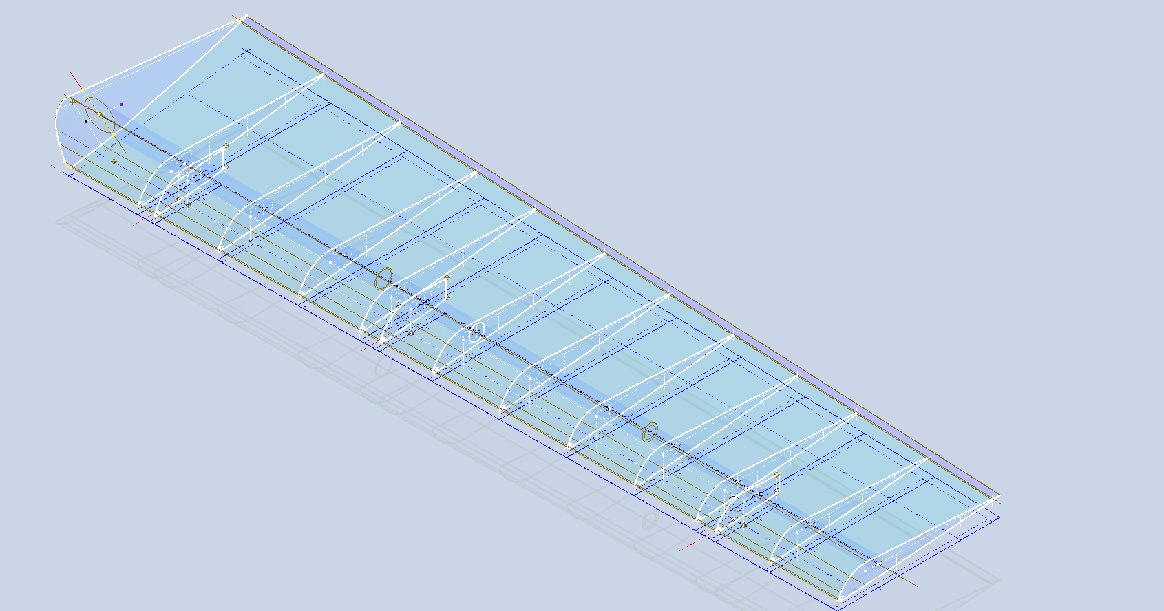
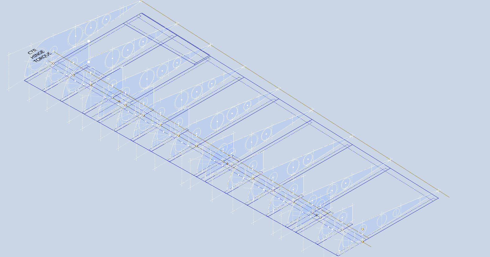
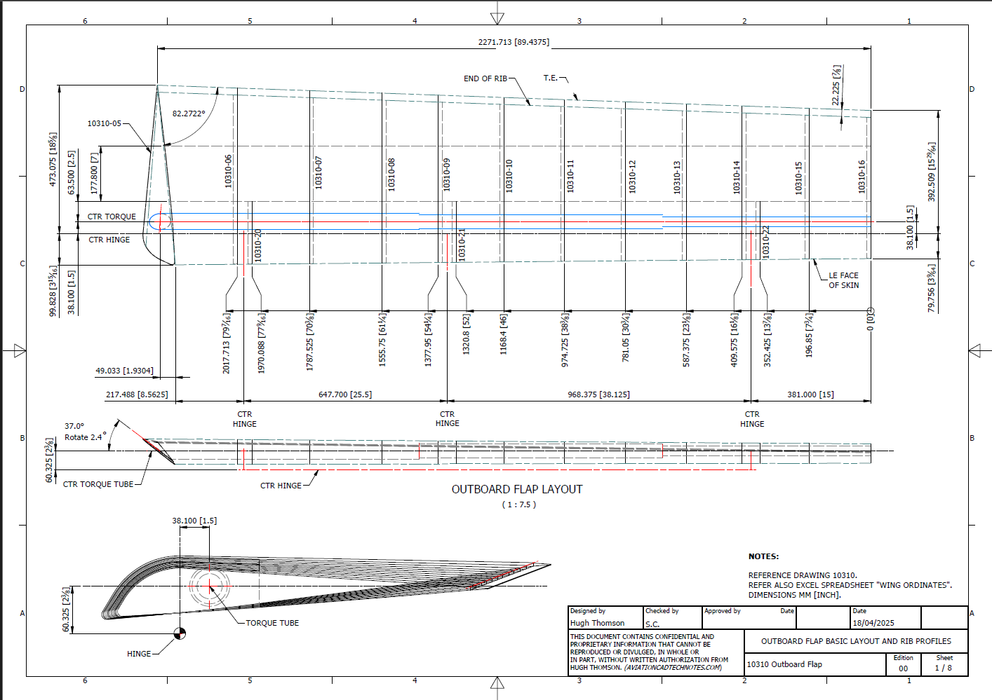
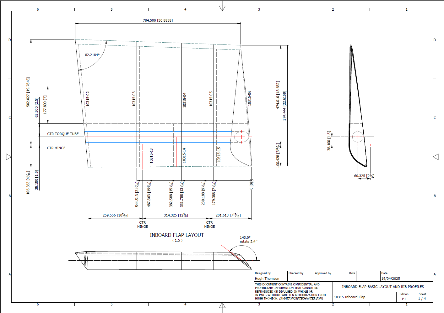
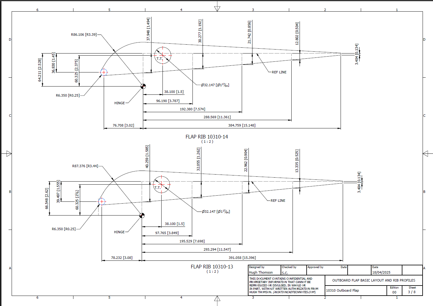
I have added new updates to the FM2 CAD/Ordinate dataset, completing assemblies for the Aileron, Outboard Flap, and Inboard Flap. In addition to the 3D CAD models, we have the fully dimensioned 2D drawings defining the profiles for all ribs.
Wing Layout and Rib Profiles:
The wing ribs comprise 3 separate rib profiles for the Leading edge, Mid-section, and Trailing edge. The detailed drawings show the complete profile and the individual component profiles separately. This will identify the blueprint drawing number in each case and the related blueprint scan file name.
Every drawing will be available as a full size Autocad DWG. All rib profile offsets are listed in a comprehensive Excel spreadsheet.
The first of the F4F/FM2 Project models will be ready from the 1st of March 2024. This is the first in a series of accurate CAD models for the F4F/FM2 Horizontal Stabiliser and Elevator. These models will only be available to project sponsors. Download links will be emailed to the sponsors on 1st March 2024.
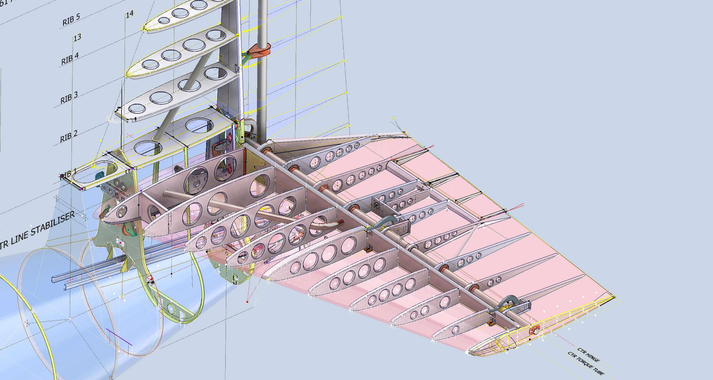
These images show the work in progress. I still have the Elevator Trim Tab, Trailing Edge and the lightening holes to add.
The red profiles at the ends of the Elevator are the skin end caps…all models will include skin profiles for reference. The single rib shown in blue is still to be dimensionally verified.
As usual all inquiries to hughtechnotes@gmail.com.
Update: 4th March 2024:
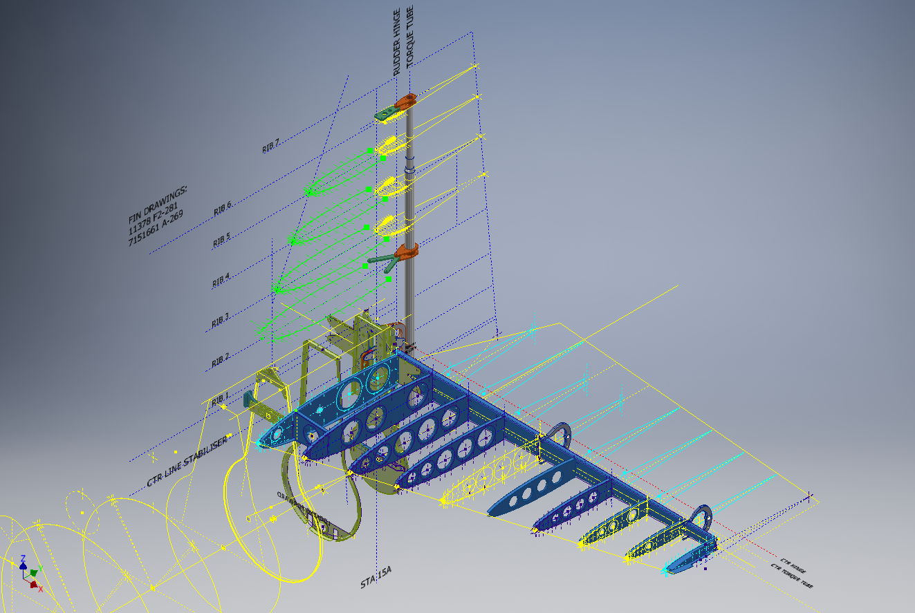
The horizontal Stabiliser and Elevator model is now done as far as is possible from current known information. As we don’t yet have details for the actuator this is not included…further research will hopefully provide more information.
I thought I might share some images on the progress of the F4F/FM2 project.
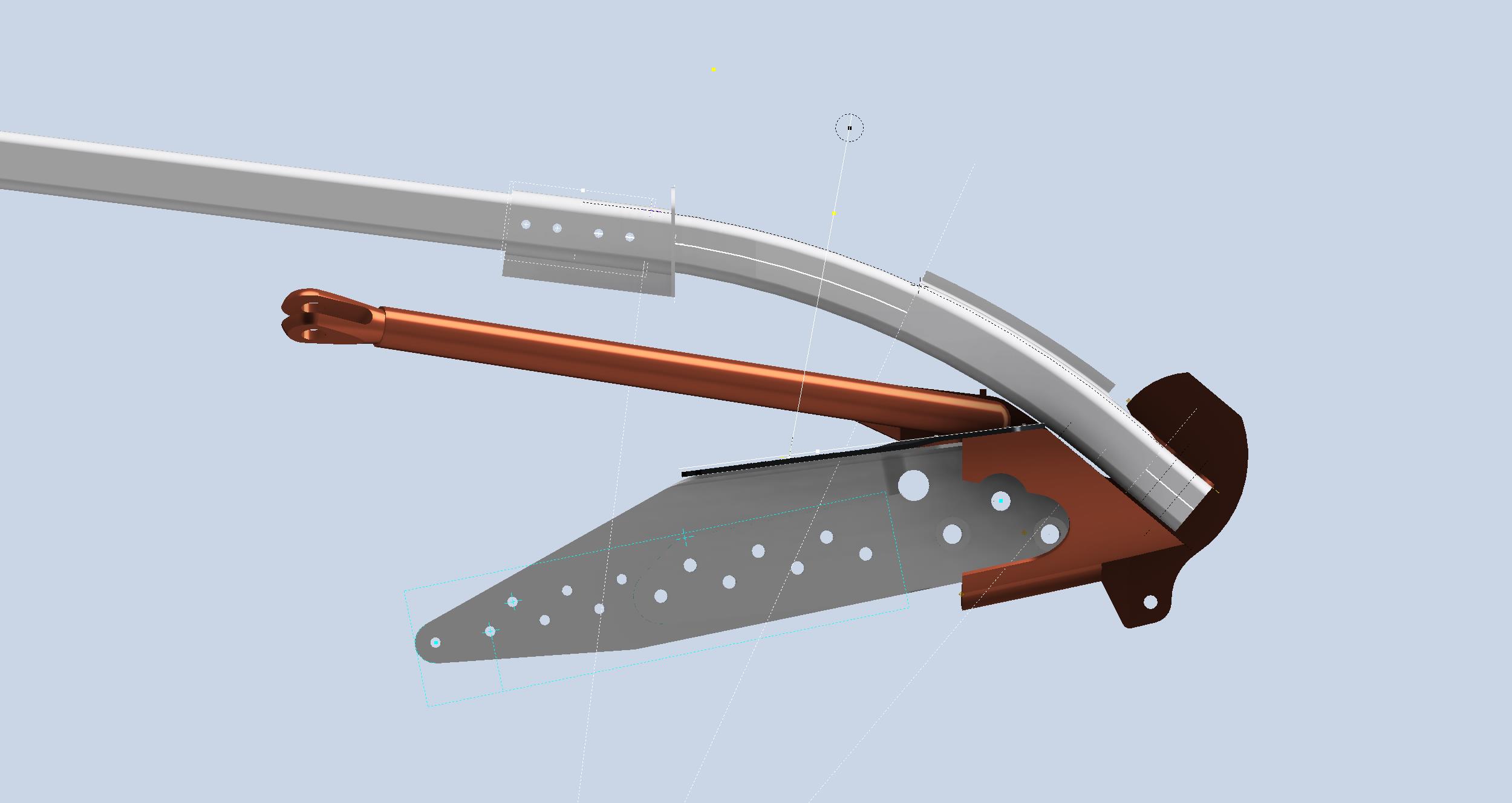
Arresting Gear Assembly:
This is surprisingly complex partly due to the poor quality of the blueprint archives, but also the fact that the key setting out information is fragmented and spread out over several resources; drawings and manuals.
I plan to document everything I have learned about this area and develop a single drawing showing all the key dimensions and datums for establishing the association between all the different components, fuselage bulkheads, and profiles for the skin surfaces.
Fuselage Updates:
Alongside the above, I have also been working on some updates to the fuselage bulkheads at Stations, 14, 15, and 15A. On the forward section of the fuselage, there are some minor updates at Stations 2 and 3 and a fully modeled bulkhead at Station 6.
I haven’t seen much daylight in this past week, literally working day and night on this project. Nothing is taken for granted nor assumed so a lot of time is spent on cross-referencing data and sourcing additional information. The project is moving forward quite well but I really need to take a few days off away from this computer so it may be a few weeks until my next update.
January has been a busy month with updates to both the F4F/FM2 and P-39 projects. The former CAD project now includes bulkheads at Stations 3 and 4 as well as ongoing work with the Landing Gear, Engine Mounts, Station 2 bulkhead, and Station 5.
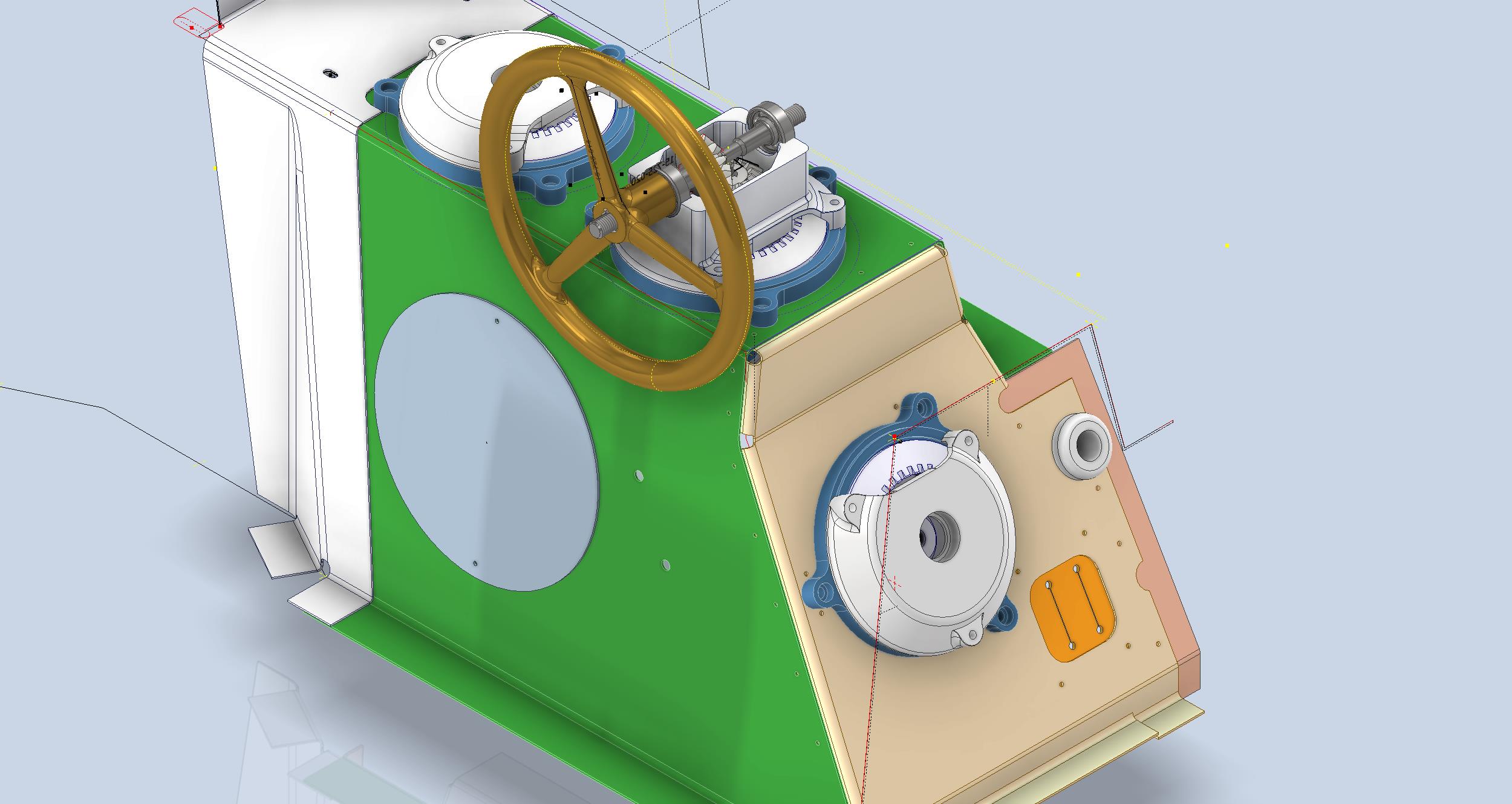
The P-39 project focus is now on the Cockpit arrangements starting with the Trim Tab Control Unit located adjacent to the pilot seat. The initial requirement is for the sheet metal work which is now complete and fully detailed with flat patterns. The dials you see are for a future requirement that may be 3d printed. I have also calculated the geometry for the gears and pinions if we need to manufacture new parts…this has all been tabulated in a separate drawing.
As mentioned previously these models will only be available to sponsors. The basic CAD/Ordinate datasets though are still available as listed on the CAD Resource page.
If you would like to sponsor either of these project builds then please get in touch at hughtechnotes@gmail.com
The F4F/FM2 project will be an accurate full structural 3D CAD reference model and likely will be ongoing for most of this year. The P-39 CAD project is dictated by the current restoration at Planes of Fame and is fully detailed for manufacturing purposes.
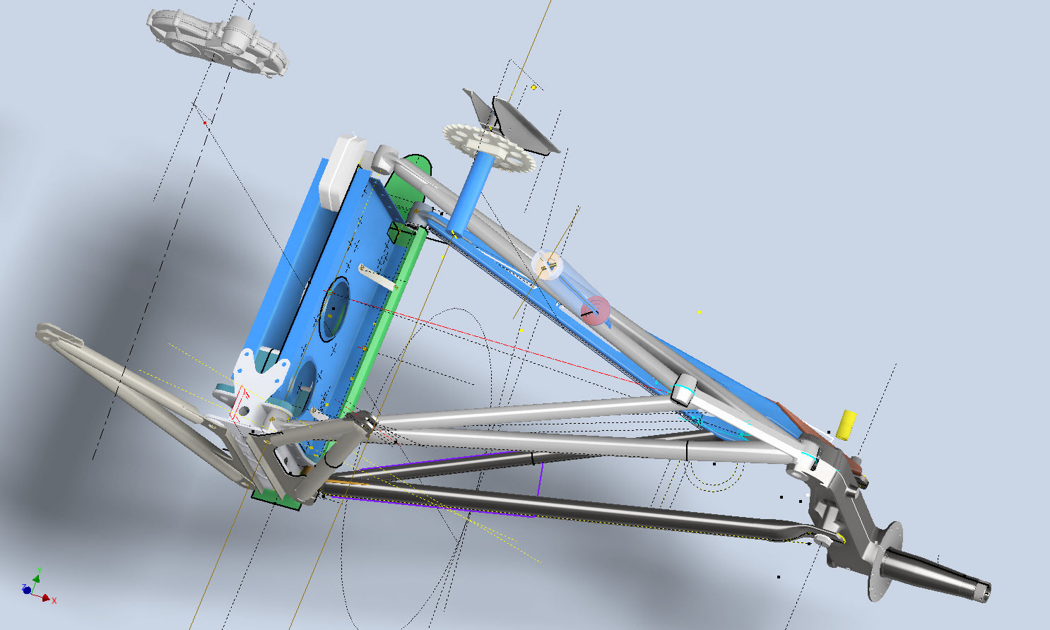
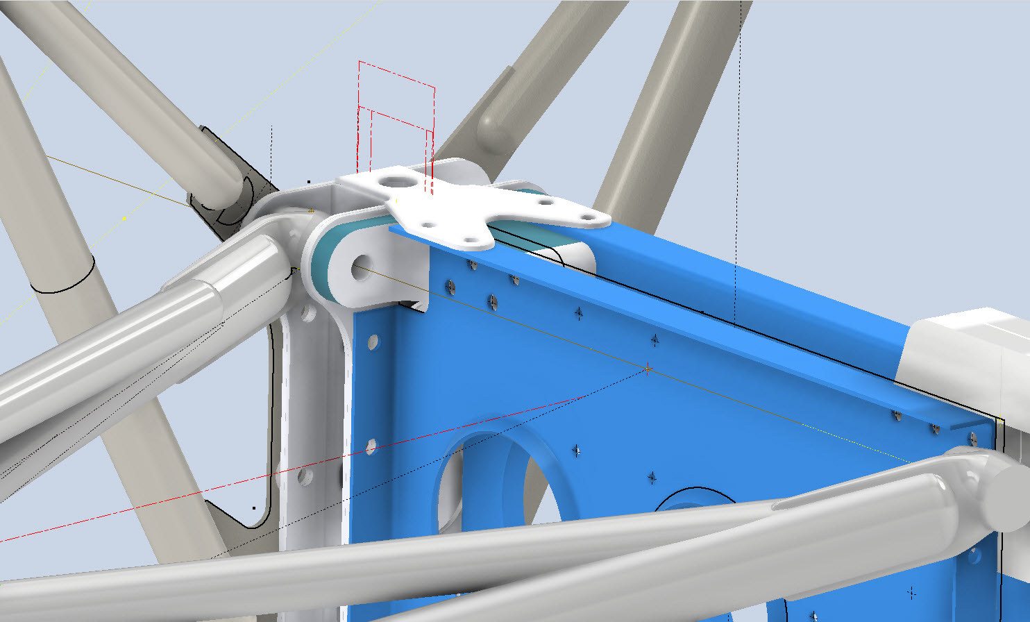
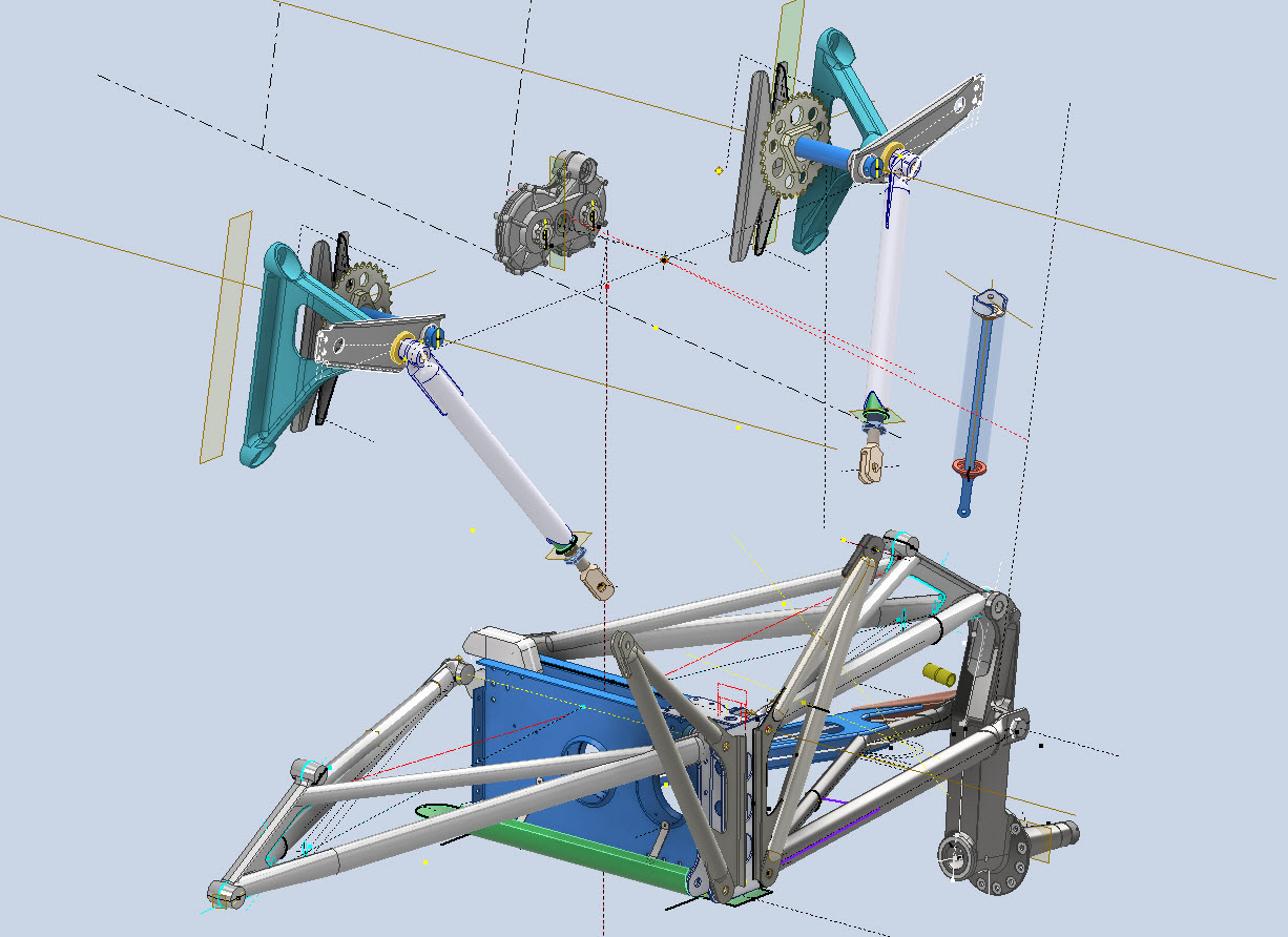
I have been busy with the Landing Gear CAD model for the F4F/FM2 Landing Gear assembly.
These images give you some idea of the progress to date. This is quite a challenging project due in part to the poor quality of a few drawings but also to the ongoing checking of dimensional relationships between the parts. Most notable is the forward Drag Link Support where you can see several red lines which is a visual indication of stated minimum and maximum tolerances. Also on this part, it is worth noting that the top pair of main holes are at 4.0625″ x/centres whereas the lower pair is at 4.1557″ x/centres…a minor variation but obviously critical dimensions.
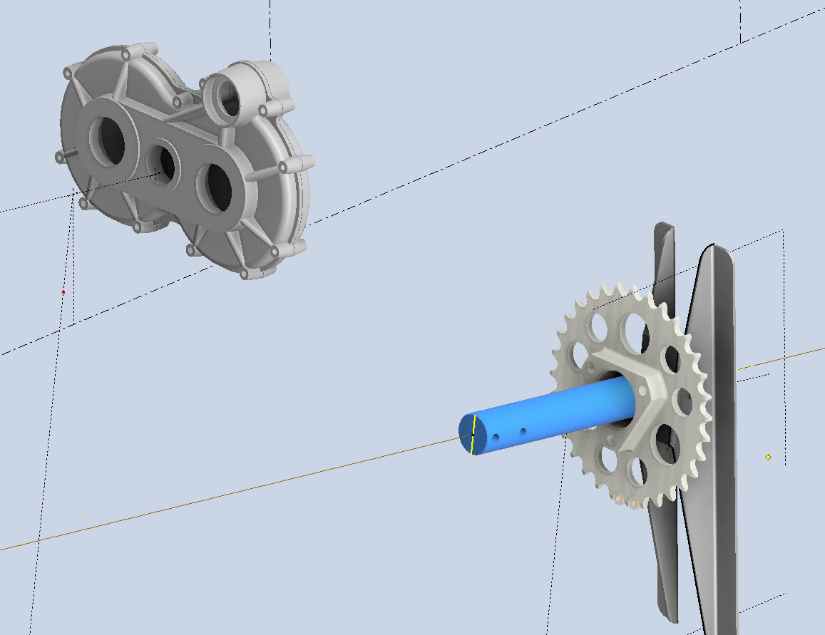
The roller chain sprocket is a calculated profile to suit the specified roller chain; there is a smaller sprocket yet to be added to the Retracting Mechanism gearbox. This part of the project will take a while to complete and it will eventually also include the Engine mounting frame.
The ordinate dimensional study for the f4F/FM2 Wildcat will now be ready in January. This will include dimensional information for all the rib, strut, and frame profiles fully documented in 3D CAD, 2D drawings, and Excel spreadsheets. Probably the most accurate dimensional study available.
In January I will be taking this project and the P-39 Airacobra to the next level. The plan is to fully 3D model in CAD all the primary structural components for the wings, flaps, ailerons, elevators, rudder, fuselage, empennage, cowl, and landing gear; and then produce a 3D printed scale model at either 1:15 or 1:10 scale. The F4F empennage is already partially fully 3D modeled in CAD which gets us off to a good start in the New Year.
These models will be printed on an Elegoo Saturn MSLA printer capable of producing a 0.02mm accuracy. The resin I will use will likely be PLA with a 10% mix flex resin to minimize brittleness. This is an ambitious project and will take most of the year to complete.
Many of the components are thin-walled profiles which may have to be adjusted to suit the scale of the printed model. Some testing will be done to find the minimum thickness to achieve model integrity and maintain dimensional accuracy.
This project is something I have been thinking about for a long time which is only now possible with the incredible accuracy achievable by the latest 3D printing technology. The final 3D CAD model; suitable for 3D printing; will NOT be available publicly but I am open to the idea of private sponsors.
As usual, all inquiries to hughtechnotes@gmail.com
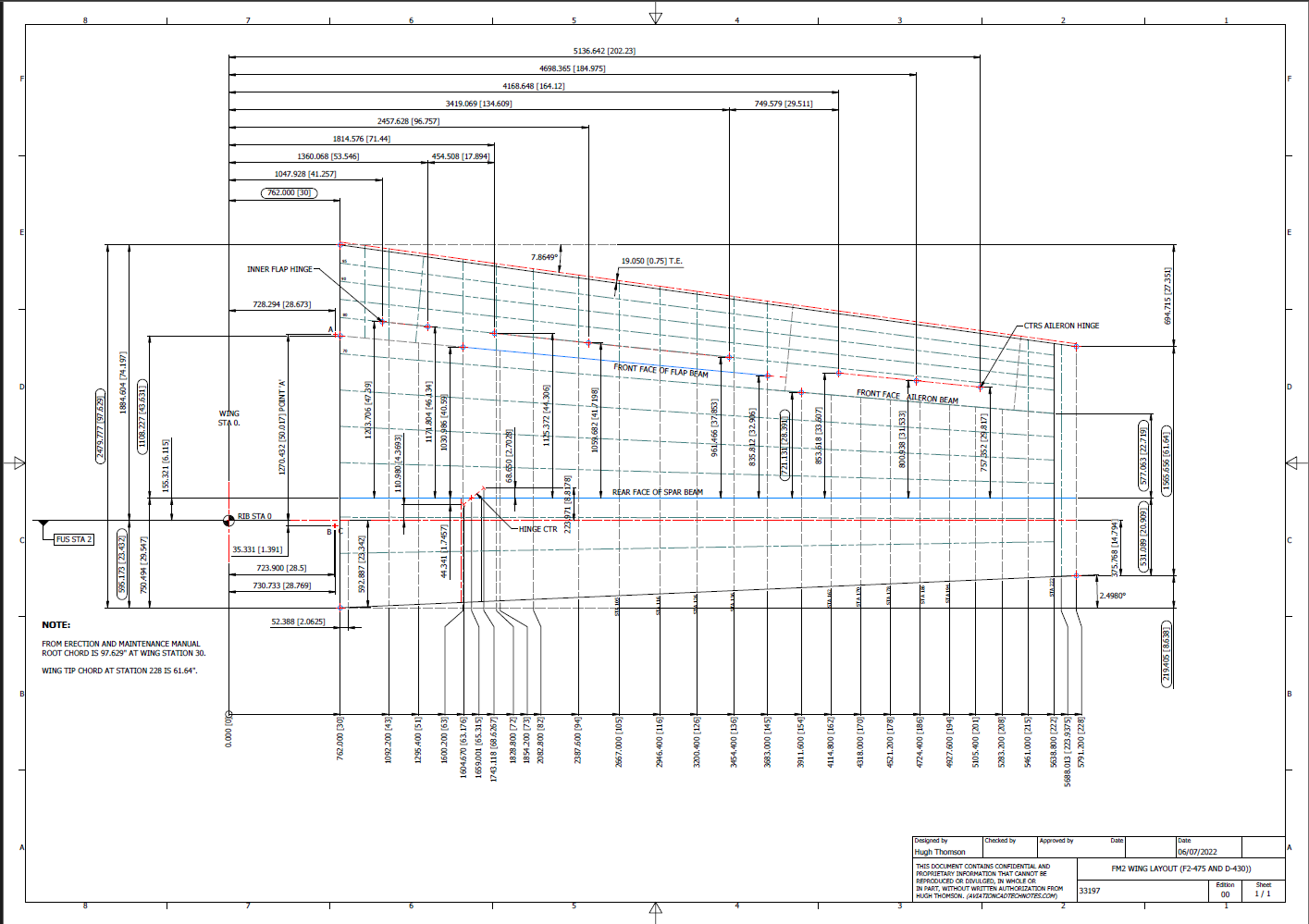
Since my last post, I have further developed the Wing layout which has revealed a number of key considerations that you may be interested in.
Wing Trailing Edge:
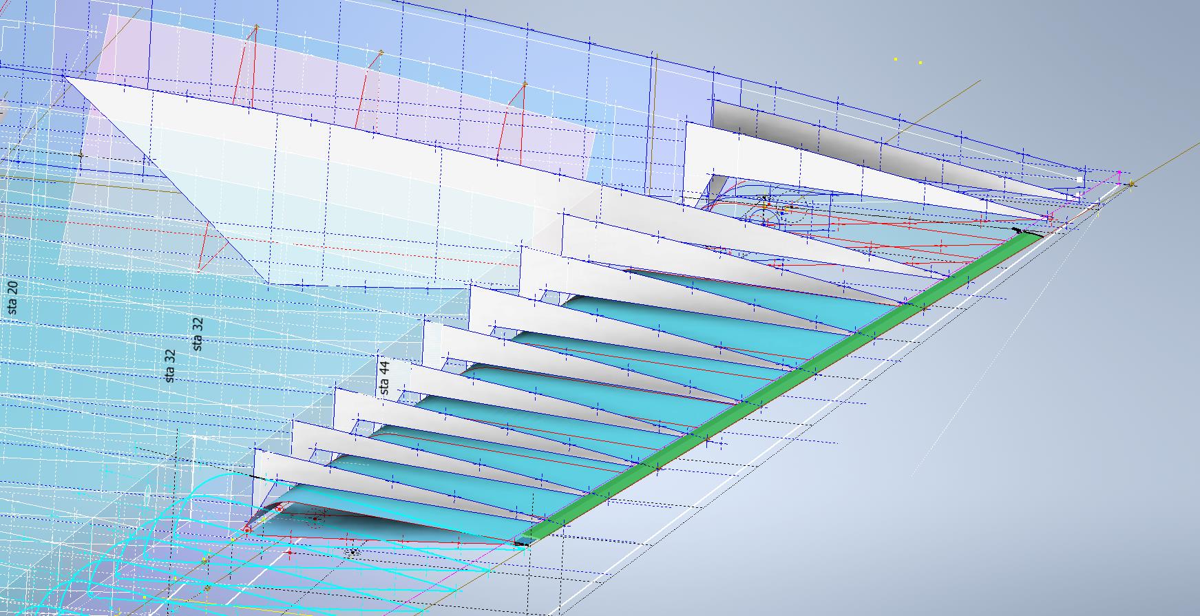
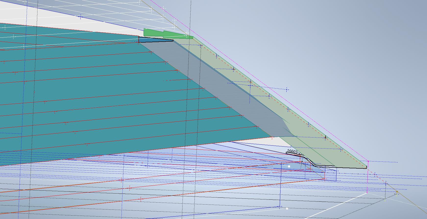
Other than a noted offset on the rib drawings there is no definitive alignment specified for the Wing Trailing Edge. What I found was the Wing Trailing Edge rib profiles were reasonably accurate from which I could determine this alignment.
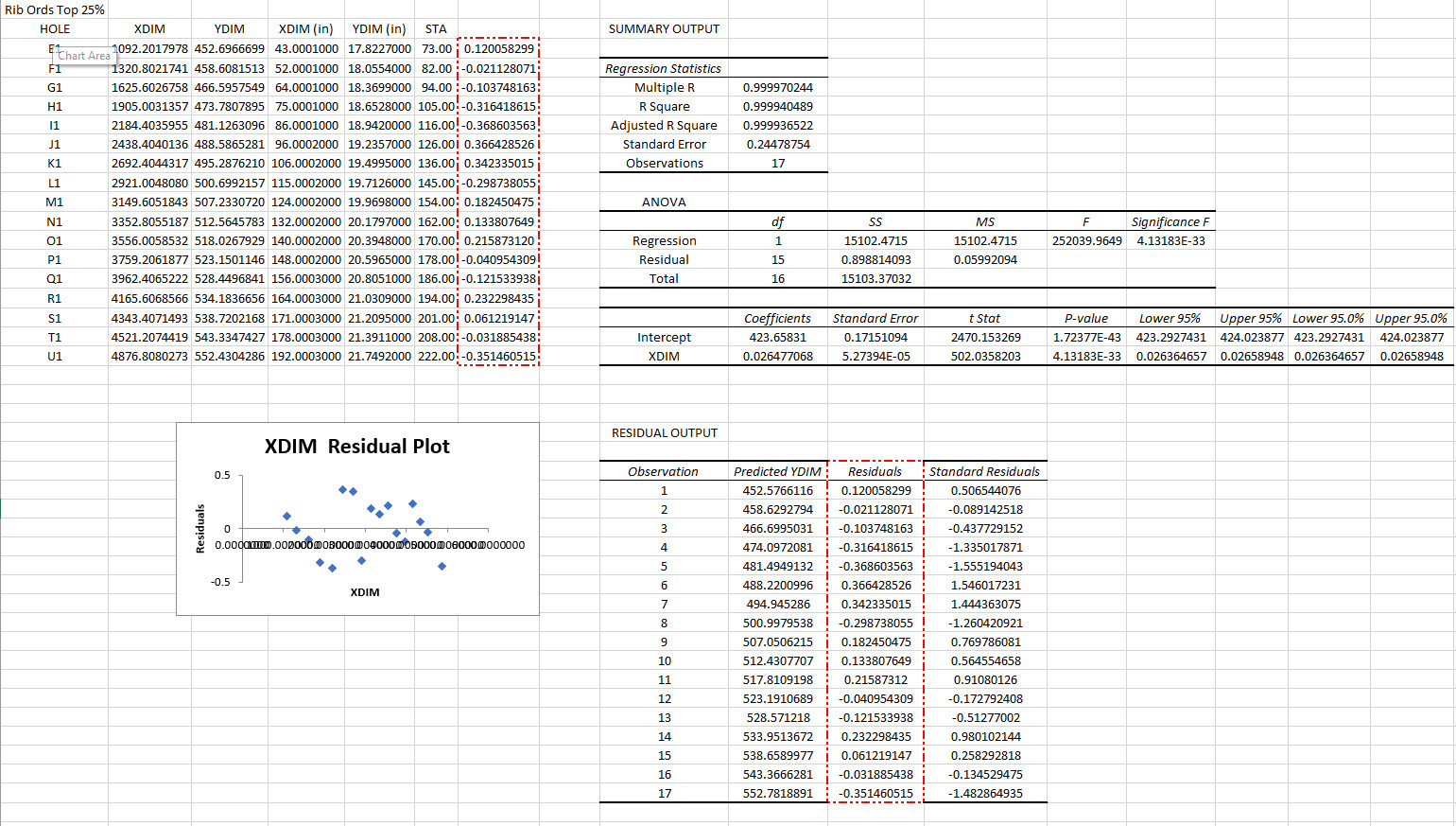
The component shown in green is the Alcoa K14403 standard Grumman profile for the trailing edge. When I developed each of the wing TE profiles (white) there was a minuscule variation in the alignment, so I needed to determine the best-fit line through those points using Linear Regression Analysis. I could just have easily selected 2 random points from the wing TE profiles which would have been okay but I like to get this stuff right.
By using Linear Regression there is no guesswork or random selection it simply analyses the point coordinates and calculates a line that best fits all these known points. As we have 11 coordinate points to analyze the end result will be an accurate placement of a Trailing Edge line that represents the collection of known coordinate points. The column named Residuals is the offset from the known coordinates to this line. As you can see the max offsets are in the region of 0.3mm…well within normal fabrication tolerances.
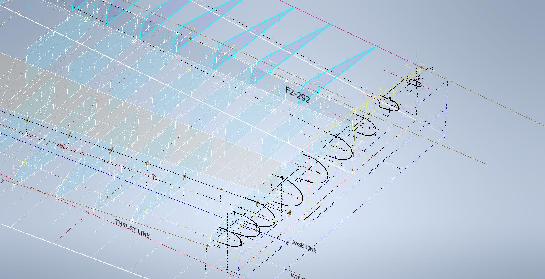
Having now established a correct Trailing Edge I checked this against the flaps (cyan) to see how well the assembly aligns with this newly defined trailing edge. I noted a deviation of 2.2mm on the outboard edge towards the wing tip.
Flaps:
In the image above you can see how the flap assembly does not align exactly with the wing trailing edge. My first impression was that I had made a mistake with the model, so I rebuilt it resulting in the same deviation. So I checked the location of the hinges…they are dimensioned to 4 decimal places of an inch so for all intents and purposes they are exactly located. Further research reveals that there is a return spring on these flaps and I think what is happening is the flap layout is deliberately set out this way so the flap first engages with the wing at the control cylinder end and then the return spring engages closure with the outboard end…hope that makes sense. Grumman has used this type of spring mechanism to engage the closure of wing surfaces elsewhere at the wing folding mechanism.
I believe the geometry for the flaps is correct however my dilemma is whether or not to adjust the alignment to align perfectly for the future purpose of design analysis…and of course should there be any interest in the development of an RC model. One to ponder.
Wing Folding Web:
On the inner wing stub section, there is a sloped web plate attached to 3 triangular gussets. This is basically the mating plane for the wing stub and the main wing assemblies at the wing folding joint. This is one area that is not so accurately dimensioned…when you develop the triangular gussets there is a slight variation in the edge slope that this web plate is fitted to and similarly, the profile of the web plate is also marginally out. We are talking about fractions of millimeters but it does matter. I developed this area in a separate assembly where the wing ribs were lofted and then the triangular ribs and web plate were sectioned. Incidentally, the second image above is the only drawing (#7150645) that indicates the slope of this web plate at 50 degrees. You can also see the numerous datum lines that we have for setting out this wing that I mentioned in previous articles.
The mating portion of the outboard wing that engages with this web plate is the spring-loaded assembly I mentioned above…I have yet to do that part…will probably feature in a future article.
Wing Folding Hinge:
Just a quick update on the Wing Folding Hinge. I have this fully dimensioned now as an ISO View, Front and Side elevations which enables alignment checks with associated ribs and web plates. It is important that the rear face of the main spar aligns with the center of the hinge so these dimensions help establish this correct relationship.
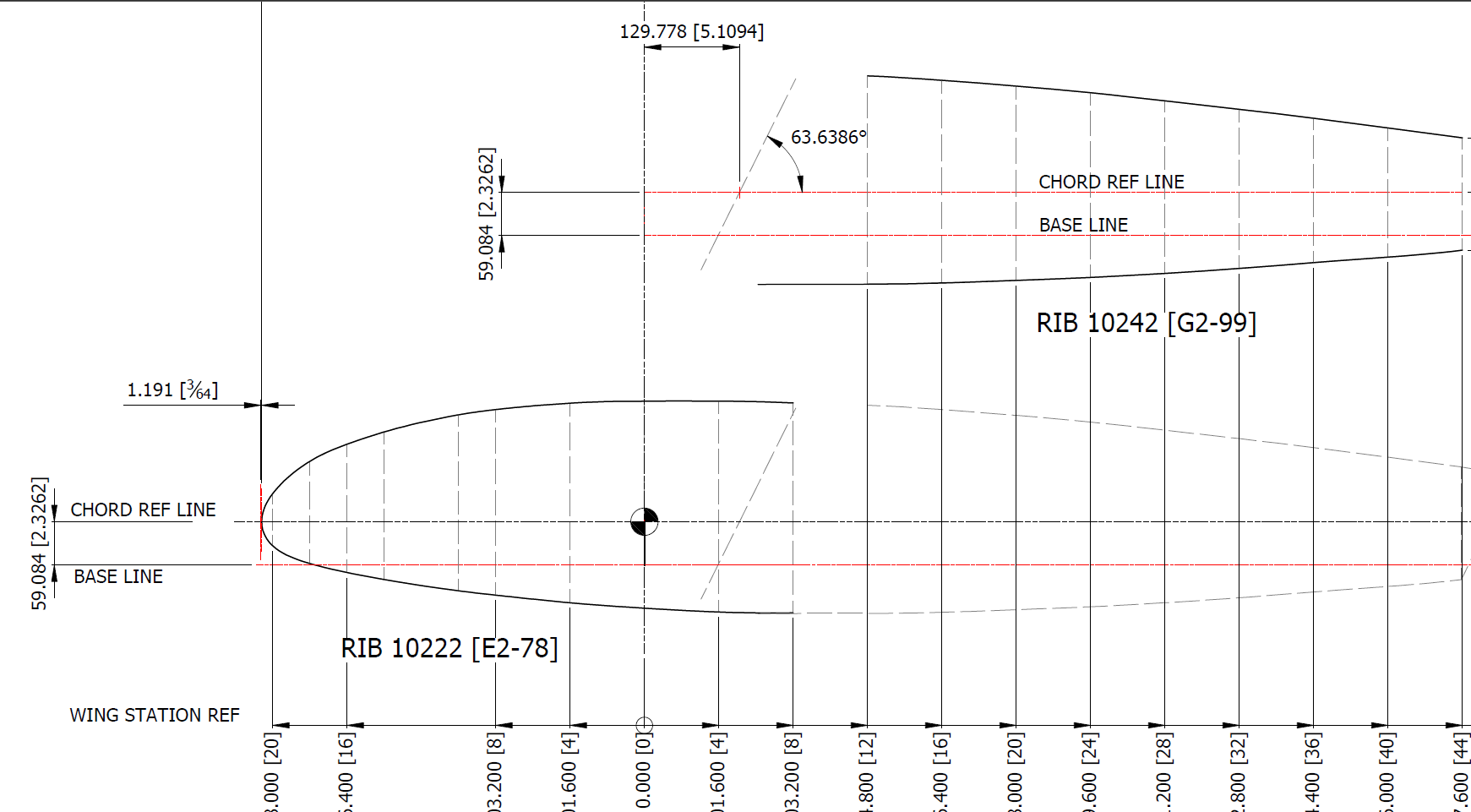
Wing Tip:
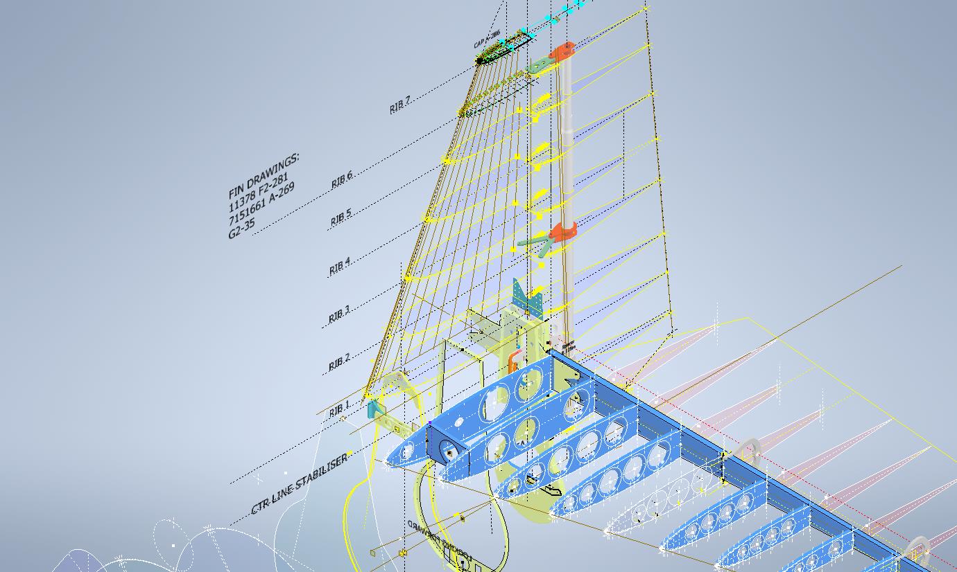
The wing tip sketch profiles are now drawn but there appears to be a slight mismatch with the wing tip rib profile at Sta 222. The Trailing Edge at 55/64″ below the Chord LIne was also puzzling as it did not align with the Trailing Edge line mentioned above. Again my first impression was that I made a mistake with the rib profile…drawn again…same result. I then checked the alignment with the Aileron assembly and whilst the wing rib TE aligns with the Aileron TE the Aileron does not align with the Wing Trailing Edge line.
This one is a bit more difficult to comprehend as there is no logical reason for the Aileron to essentially drop toward the Wing tip…yet the wing tip rib and aileron align well. Again I checked the hinge locations and they are exactly where they should be. I have been in touch with a number of museums and restoration companies to see if they have an explanation and also requested photographs along the edge of the aileron to visually examine the aileron alignment. I will get back to you on this one. By the way, I also carried out a linear regression analysis to determine the exact reference line locations for each aileron rib as a check.
This aircraft is surprisingly complex and whilst there may be perceived anomalies that at first cannot be explained there is usually a good reason for being the way they are. For example, the leading edge of the horizontal stabilizer has a negative camber towards the tip, essentially the leading drops….this is most unusual.
Finally, to make things even more puzzling the wing tip rib profile is not actually a NACA 23009…it is close in profile but it does match exactly…I believe this is a modified NACA 23009. Once I have all the ribs modeled according to the Grumman drawings I will calculate the wing rib ordinates to double-check the profiles…that will be a real pain and time-consuming thing to do as the ordinates are at 4-inch and 2-inch intervals along the chord and not by chord percentage as one would expect…so I need to transpose that data from the cad models to develop the equations for checking.
I have spent an incredible amount of time developing this wing, perhaps more than any other aircraft study I have done. This design is very complex and keeps throwing up small anomalies that at first are difficult to comprehend…it does require a lot of research to figure out the reasons why.
Update 17th Sept 2023:
Wing Rib Ordinate Check: As mentioned above I have now carried out a check on the wing rib profile ordinates. Normally I would do this the same way as I calculated the wing rib ordinates for the P-38 Lighting but that is only applicable when you know for certain the root and wing tip rib profiles. The main point of this exercise was to determine the accuracy of the FM2 wing tip profile which is apparently different from the stated NACA 23009 profile.
I resolved to do this using Linear Regression Analysis from plotted points on the 15%, 25%, 50%, and 60% chord planes. These percent chord planes actually have to be determined separately because the wing rib ordinates on the Grumman drawings are incrementally spaced at 2″ and 4″ intervals which of course does give us the straight-line projections we need.
Typically I did this for the top and lower ordinates recorded from each rib at each chord plane and compiled the resulting data into a table in Inventor which was then exported to MS Excel for analysis. The analysis confirms that the wing tip profile is accurately drawn and the ordinates on the drawing profile are correct. I shall also do a similar exercise to check the dimensions of the main beam at the flap and ailerons.
Drop me a line for further information at hughtechnotes@gmail.com
Please consider making a small donation, every contribution makes a real difference.
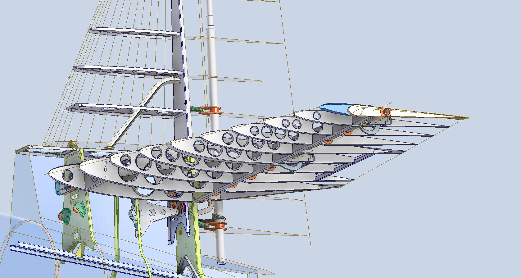
Following on from my previous posting regarding the Excel Transpose function; wherein I mentioned the updates to the Grumman F4F/FM2 Cad/ordinate dataset; I thought I would share a few screenshots of progress so far.
As you can see the aircraft is partially 3D modeled…there is actually a good reason for this other than the fact I enjoy the 3D modeling! I have found that on the main assembly layout drawings, the dimensions are often shown to one side of the spar whereas the actual connecting part is defined to the other side. To ensure I get this stuff right I would model the main spar to correct material thickness and check alignments. Admittedly I did get a bit carried away with modelling some of the ribs.
The wing is probably the most complex assembly to do due to the main ribs being in 3 parts…the leading edge, mid-section, and the trailing edge. Each profile will be recorded separately; as per the Grumman drawings and then compiled to provide full rib profiles at each station. The wing also has 5 datum lines that are occasionally misidentified in the part drawings which can be really frustrating alongside incorrectly placed dimensions…generally wrong vertical dimensions are associated with the wrong rib station, more common than I would like.
Still some work to do to finish these main areas as well as the cockpit canopy, fuselage, and front cowl. I haven’t looked at the undercarriage as yet… development of that will be dependent on available information…we will see!
It is not my intention to fully 3D model this aircraft but where it helps check associativity between parts then I will. The project will fully develop all key profiles for ribs and frames which will be fully documented on Excel spreadsheets as a permanent dimensional record. I plan to have this update completed by the end of September.
The aim of these cad/ordinate datasets is to produce the most accurate dimensional records available anywhere for the various aircraft…nothing is assumed or taken for granted.
If you can help me with the spiraling costs of these projects please consider making a small donation. As usual for all enquires please get in touch at hughtechnotes@gmail.com
Having made good progress on the ordinate set for the Grumman F4F/FM2 I decided to put the spreadsheets to one side and do some modeling to verify the dataset. Normally this would not be required to such an extent but I needed to do this to check the relationship between the components and aircraft datums.
I was spoiled with the P-39 project where virtually every component has reference dimensions to the ship center line or thrust lines so positioning was a breeze. However, the F4F drawings sadly lack this reference information on many of the key drawings so developing the 3d cad model is the only sure way to ascertain this data.
The above model is the left-hand Aileron modeled in Inventor and rendered in Keyshot. Keyshot is a very good renderer, even for a novice like myself; in which you can generate acceptable renderings very quickly. The real-time rendering is very good and will continue without glitches even on a modestly specced system (unlike some of the alternative products). The user interface is logically set out with a good library of materials and textures. I would highly recommend this product.
Getting back on subject; the Aileron ordinates took a long time to complete for various reasons; requiring constant checking and verifying. Once this was done, the modeling was reasonably straightforward except for the small trimming tab. The drawing dimensions are slightly out, so I extracted the neighboring rib profiles to create the template for a finished model.
I also decided to create a few scrap drawing views as a matter of record that will be useful when I eventually move onto modeling the wings themselves.
For reference; the following image shows the Ailerons attached to the wing assembly. Hinge positions checked and verified with hinge brackets (orange) fitted achieving a planar variation of less than 0.04mm.
There are still a few items required to complete this model but this is not a priority for me right now. My next objective is to develop the ordinates and perhaps some modeling for the vertical and horizontal stabilizers.
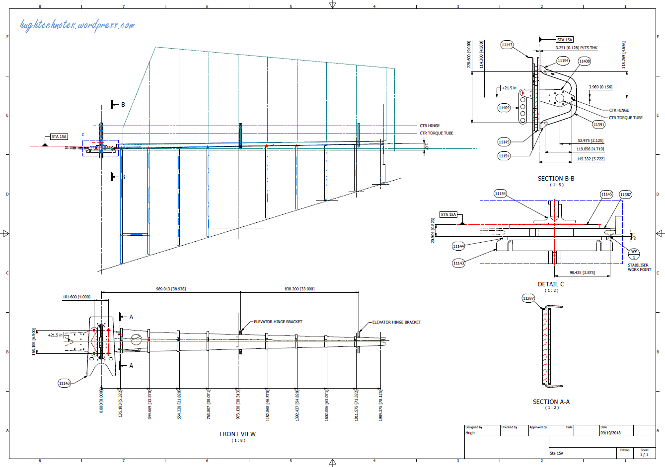
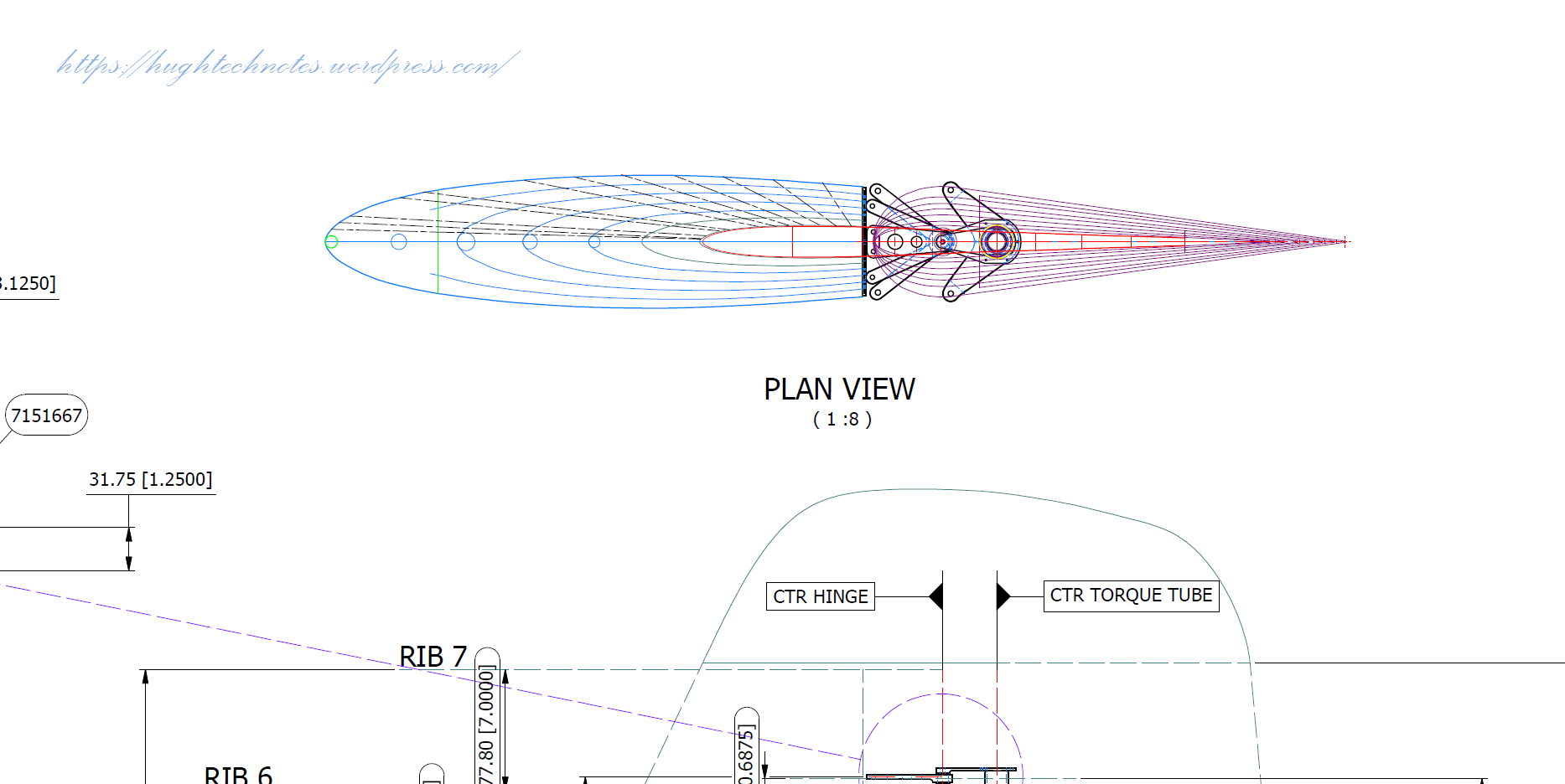
Horizontal Stabiliser & Elevator:
Tail Fin & Rudder:
Fuselage Frame 3:
If you are interested in obtaining my research data for this aircraft then please send me an email. At the moment this is an unfinished project but the available drawings (12) are fully dimensioned which will help you with establishing correct datums and station frame associations along with a few spreadsheets. HughTechnotes@gmail.com