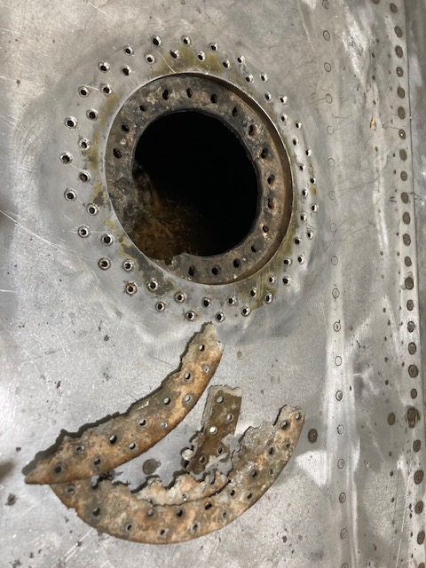
The P-39 restoration project is still very much a work-in-progress. The latest addition to the project is the Fuel Tank Covers and Filler Cap. When the existing components were removed there were visible signs of corrosion so it was decided to replace the inner mounting rings as well as the covers/caps.
Each cap assembly consists of an inner mounting ring, a Goodyear-type sealing ring, and cover plates. It is important to consider the varying thicknesses of the sheet metal at each location, as this can lead to slight differences in the profiles of the mounting rings. Typically, when we develop these types of parts, we mark the holes in situ based on existing hole patterns to ensure a proper fit. This is usually done because the holes are evenly spaced between two known locations, which can vary during manufacturing. However, for these covers and caps, we have precise knowledge of the hole locations, allowing us to ensure an accurate match.
The flush rivets used throughout are the 35R1 Bell standard, featuring a 120-degree countersink designed for thin sheet materials. An equivalent Boeing standard for this type of rivet is also available. In the assembly drawings, I have spaced the components apart to enhance clarity. I should note that the drawings shown are still a work in progress.
Update: Ready for issue:
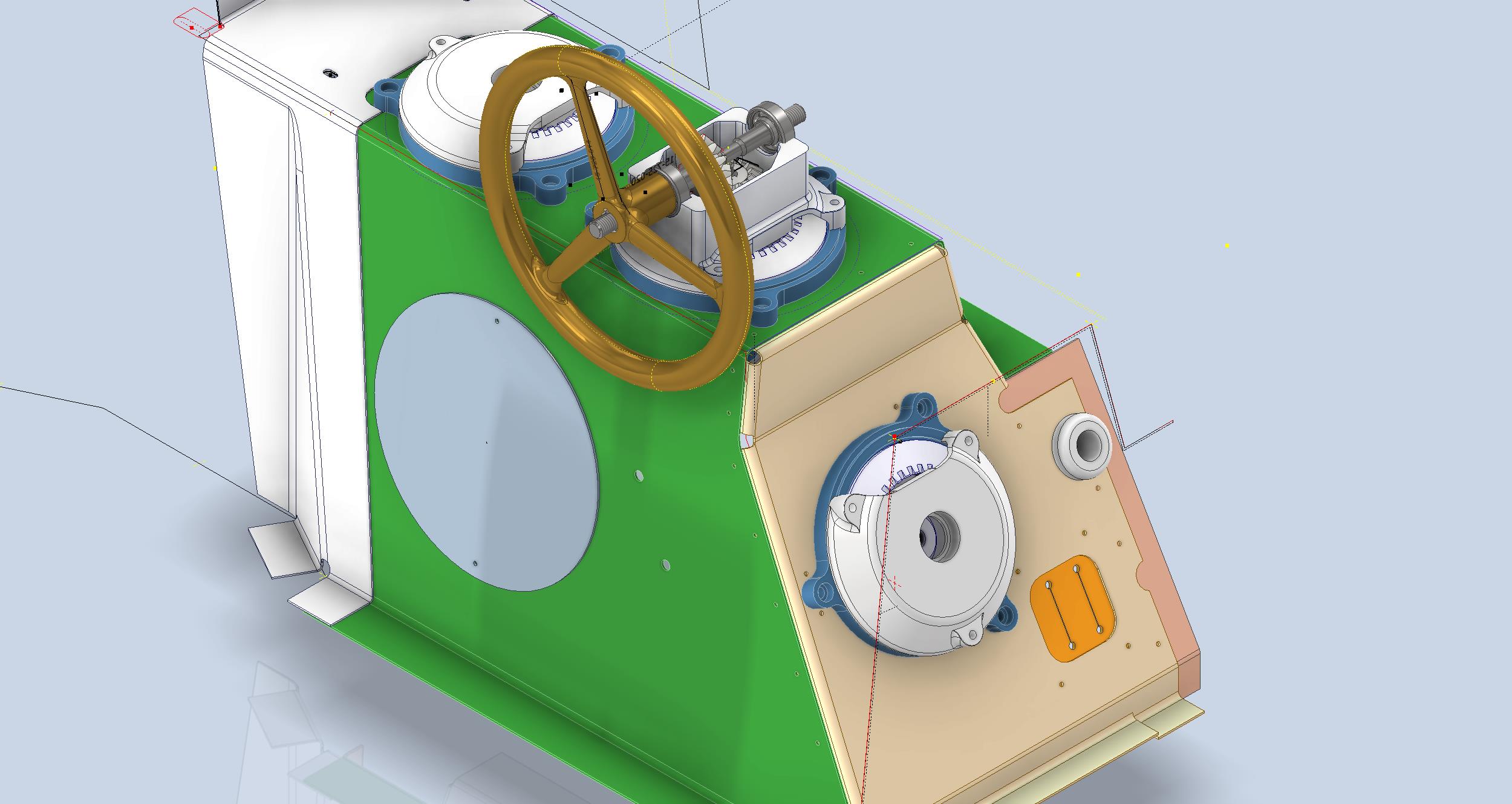
This is the final assembly, typical for the fuel tank covers and caps.
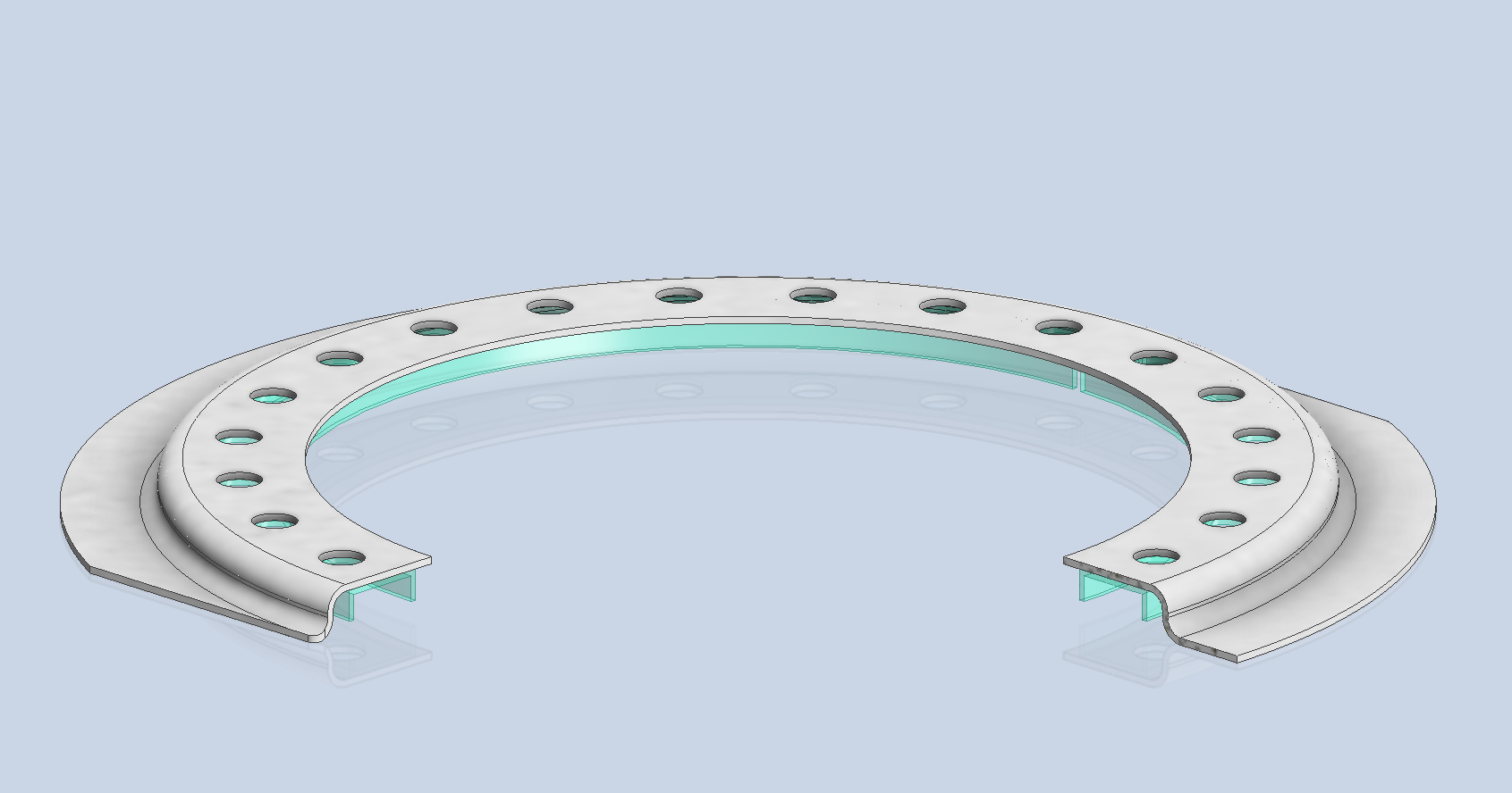
The lower ring features an Elastic Stop Nut Gang Channel. It is presumed that this channel was designed according to Bell standards when it was constructed. I have examined various companies that supply similar Gang Channels; however, the hole centers in their standard components differ slightly from our specifications. I suspect that we will need to have a bespoke fabricated item to meet our requirements.
It may be possible to purchase Elastic Stop Nuts and retaining springs from companies like Howmet Aerospace and create a channel to match the design in the second image below. I will provide an update later on how we will proceed.
I will also soon be able to provide you with more information about the P-39 restoration and a gallery of images showcasing the latest work.
January has been a busy month with updates to both the F4F/FM2 and P-39 projects. The former CAD project now includes bulkheads at Stations 3 and 4 as well as ongoing work with the Landing Gear, Engine Mounts, Station 2 bulkhead, and Station 5.
The P-39 project focus is now on the Cockpit arrangements starting with the Trim Tab Control Unit located adjacent to the pilot seat. The initial requirement is for the sheet metal work which is now complete and fully detailed with flat patterns. The dials you see are for a future requirement that may be 3d printed. I have also calculated the geometry for the gears and pinions if we need to manufacture new parts…this has all been tabulated in a separate drawing.
As mentioned previously these models will only be available to sponsors. The basic CAD/Ordinate datasets though are still available as listed on the CAD Resource page.
If you would like to sponsor either of these project builds then please get in touch at hughtechnotes@gmail.com
The F4F/FM2 project will be an accurate full structural 3D CAD reference model and likely will be ongoing for most of this year. The P-39 CAD project is dictated by the current restoration at Planes of Fame and is fully detailed for manufacturing purposes.
An update on some recent work I have done for the P-38 Lightning and P-39 Airacobra. For the P38 Lightning, I now have the Boom Tailend interface with the Empennage and for the P-39 Airacobra, the new work includes the Auxiliary Fuel tank, Wing and underside panels at the Centre Section.
P-39 Airacobra Wing Layout and Aux Tank:
I was doing some research into the various closed penetrations on the underside panel as shown in the photograph on the right. So I modeled this panel to get a clearer idea of what was happening in this area as marked “A” in the underside view and front view images above. The 2 oblong holes are actually openings that normally would have a curved reinforcement which I understand would be used for the Auxiliary Fuel tank pipes and hoses. The Teardrops are for domed covers, which you can see more clearly in the first image view.
The Square cutout towards the rear of the panel is for the exhaust Flap and the slot to the front is for a removable panel that houses the Auxiliary Fuel tank mounting. The Aux fuel tank itself was well documented and was an interesting model to develop…I still have the fuel cap and vent pipe to add along with a few bracing struts to complete.
Following this exercise, I decided to further develop the wing layout. Although the CAD work for the wing was well-dimensioned with outlines for the Wing plan, Front Beam, Rear Beam, and Aux Rear Beam there was not much information on the actual rib profiles. We know that at STA 1 (22″) from the center of the ship the rib profile is a NACA 0015 and at the wing tip this is a NACA 23009 profile (204″ outboard). Other than that we have virtually no ordinate information for the ribs except for a partial profile at STA 7 +7.
The arrangement for the wing has been a subject of debate on several forums mainly regarding the construction of the Wing Tip. Usually, when there is a change in the rib profile the change occurs at the intersection of the wing tip and main wing however in this instance it is located at the extreme point of the wing tip. So the surface model is based on a loft between the 0015 profile at the root and the proxy 23009 profile at the extremities. This loft reveals an interesting caveat related to the evident wing twist and alignment of the Leading Edge.
Clarification on the location of the different NACA profiles was actually found in the NACA Report L-602 on the Flying Quality of the P-39 which defines the relative positions of the profiles. The caveat I was talking about relates to the wing twist…normally when we think of Wing twist or Washout we visualize the rib rotated about the 30% or 35% chord with the leading edge dropping and the trailing edge lifting slightly…but that is not what is happening here. The entire 23009 rib drops from a static position at the trailing edge towards the leading edge…the rotation is roughly 1.257 degrees. This results in a continuous leading edge downward alignment all along the length of the wing from the root to the tip.
As this is most unusual I was able to check the resulting surface model against known dimensional information for the beams and the partial profile at STA 7 +7 which matches. I still have to model the wing tip which has an interesting upward curvature.
P-38 Lightning Boom Tail End:
Another challenging aspect of the P-38 Lightning was determining the geometry for the Boom Tailend…essentially the intersection of the Boom and Empennage. We do have the lines of intersection for the Vertical Stabiliser, Horizontal Stabiliser, and the end of the boom but we don’t have any dimensional information for the curved profiles though we do have drawings that give us some idea of the profiles.
This was surprisingly difficult to get right and to be honest this final version is the result of 3 different attempts to achieve a viable solution. At first, I attempted to draw the Boom section, and stabilizers then fill the void with a surface patch to naturally define the curved fillets…with a few guidelines I managed to get a reasonable result but I incurred a few anomalies with the finished surface which I couldn’t correct. The second effort was more structured with a number of contours traced from the available drawings as a reference to gauge the curvature and then try again with surface patches but this time is broken down into quadrants, top 2 sections, and bottom sections…this was better and very close but again I had a few surface deviations at the leading edges.
Finally, I decided to have a look at using variable radius fillets…although I had already tried this unsuccessfully I changed my approach slightly which gave me good results. The fillets I used initially were tangential which caused a few problems where they met particularly on the top surface…what was happening was a sharp edge developing where the fillets intersected…so that was no good. It also mattered in which order the fillets were generated.
Eventually, I figured why not try G2 fillets and see if that worked…I am always wary of using G2 fillets due to some bad experiences using them before but I was running out of ideas and I was keen to find a workable solution. I started with variable G2 fillets at “1” and “2” with several control points to control the curvature and avoid folding the surface at the leading edges. After some fine-tuning, this worked out well for the first 3 locations. The remaining fillet for the Vertical Stabiliser did not go quite so well as it was impossible for the CAD software to give me a G2 variable fillet…so this one ended up being tangential. Perhaps with a bit more tweaking, it may have achieved a G2 fillet but I had spent many hours on this and I needed to make a decision.
There is a very very slight edging but it is almost unnoticeable on the final product. The final curvature of this model matches well with the guidelines extrapolated from the drawings and I am satisfied it is a very good representation of the Boom Tail End.
I hope you find this article useful and as usual any inquiries please get in touch at hughtechnotes@gmail.com
Following a recent inquiry about the P-39 Airacobra, I was asked if I had a model for the P-39 Carburettor Air Scoop. At the time I didn’t, though I did have some preliminary outlines that were done as part of the dimensional ordinate study. So I decided to get stuck in on this new project and see what can be accomplished…by the way did I mention this will be used on a real aircraft. The template moulds will be 3d printed and used to form the aluminium plates.
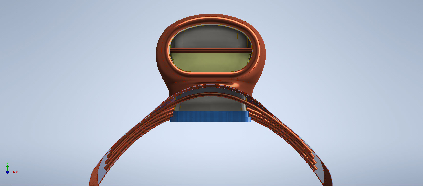
When you look at a photograph of the Carb Scoop it looks deceivingly uncomplicated however it turns out this part is surprisingly complex. The main body part itself is challenging with the curved profiles and filleted interfaces, the curvature of the fuselage; which by the way is not actually documented anywhere and the transitions from one frame to another to achieve smooth curvature. The internal duct comprises many varying profiles…the profiles tend to be rectangular with different corner radii throughout culminating in what can be described as a slot profile for the Air Scoop inlet.
I have been working on this for a few days now studying various modelling methods to achieve the most accurate and consistent results. So far I have the main scoop body and the fuselage skin modelled. The internal ductwork is set out on a sketch, though I will still have to define a number of intermittent profiles to ensure I get that right as well. Overall there are 12 individual parts for this assembly all detailed on one drawing…so some interpolation of design intent and cross-referencing with a few external drawings is essential.
At the Scoop inlet, there is a small lip that I have yet to model. The drawing has very little information on this so I decided to model the scoop without the Lip and then I will have to sculpt the curved form from extrapolated model information. That Lip at the end of the day will probably look inconsequential but the development work for such a small item cannot be understated. I shall update this article as work progresses.
An overview of the underlying geometry sketches for the CAD model. Point “1” is the fuselage skin…as mentioned the ordinates for this profile do not exist on available Bell drawings. So I work with what I know, namely the fuselage frames fore and aft and below. These were surface lofted and then the profile at “1” was patched to align with curvatures of known surfaces. using tangency and G2 on selected edges.
Point “2” is the scoop outline sketches, in which I made continuous elliptical profiles with an additional circular profile at the very tip below the fuselage plate surface.
The blue lines at “3” are the lofting guidelines, absolutely essential to getting this right. I initially skimped on this, instead, I attempted to just loft and use G2 or Tangency adjustments…it did not work well…so if you are doing this don’t skimp on these guidelines. Once the scoop body was lofted there was trimming to do with the flange plate (it was the offset from the fuselage surface) and then the 2 items were stitched. This provided an edge to which a variable fillet was applied. Cautionary note on the variable fillet…when initially applied don’t try and create adjustment points all at once…take your time, just create one pair at a time making micro adjustments and let the model regen and repeat.
The other key consideration is that the Bell drawing dimensions are generally only accurate to 1/32″ and 1/16″ (0.8mm and 1.6mm respectively). This will invariably impact the eventual quality of the end product when using CAD so it is important to understand where and how you need to compensate.
Update: Internal Duct:
I have now modelled the internal duct which has a partial concave curve on both sides to allow clearance to the main scoop housing. That was a real pain to model and to be honest, to achieve continuity with the duct curvature I simplified it slightly.
The sides of the duct are shown on the Bell drawings as being flat from the base level almost to the scoop inlet itself; merging to a point just past the horizontal breaker bar. I tried various methods of doing this but failed to achieve a good result…even using freeform curves…mathematically it is not to be! I settled for a smooth loft of the various sections to ensure that at the very least I could still achieve the partial concave surface and a smooth shell.
The front curved edge of the scoop inlet has a weld seam which is shown in the centre of the edge on the Bell drawings. I decided to move that joint further inward because an extended flange may reduce the installation clearance when installing the duct.
The curved plate you see will be cut back to finalise the flange for the scoop, which I shall leave until the main parts are all modelled. More updates to follow.
Duct Vane and Scoop Ring Stiffeners:
All inquiries as usual to HughTechnotes@gmail.com
Update 11th Sept 2022: Almost There:
Looking good and is deadly accurate. Trimmed the flange for the scoop main body and added the fuselage frame stiffeners. I still have a small panel door, forward lip and a few miscellaneous items to finish. One more day should do it.
The Main Body Sorted: Just the Lip to model and add to the finished model.
If you require a professional design and draughting service for your projects then please do not hesitate to drop me a line. Providing professional engineering, draughting (time served, old school) and modelling services in CAD since 1985. Fully conversant with Geometrical Tolerancing, Geometric Dimensioning and Tolerancing (GD&T), ISO Geometrical Product Specification (ISO GPS), BS 8888 and mechanical specification.
Email: hughtechnotes@gmail.com
Update 12th Dec 2022:
I have just received word that the P-39 Carb Scoop has just come off the 3d printer after 4 days. They printed this in 2 parts as you can see. Still a lot of finishing work to do before they have a chance to fit it onto the P-39.
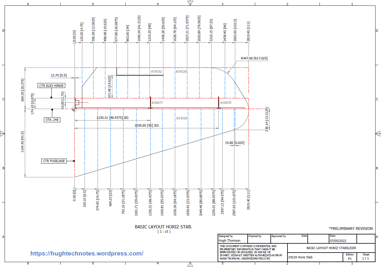
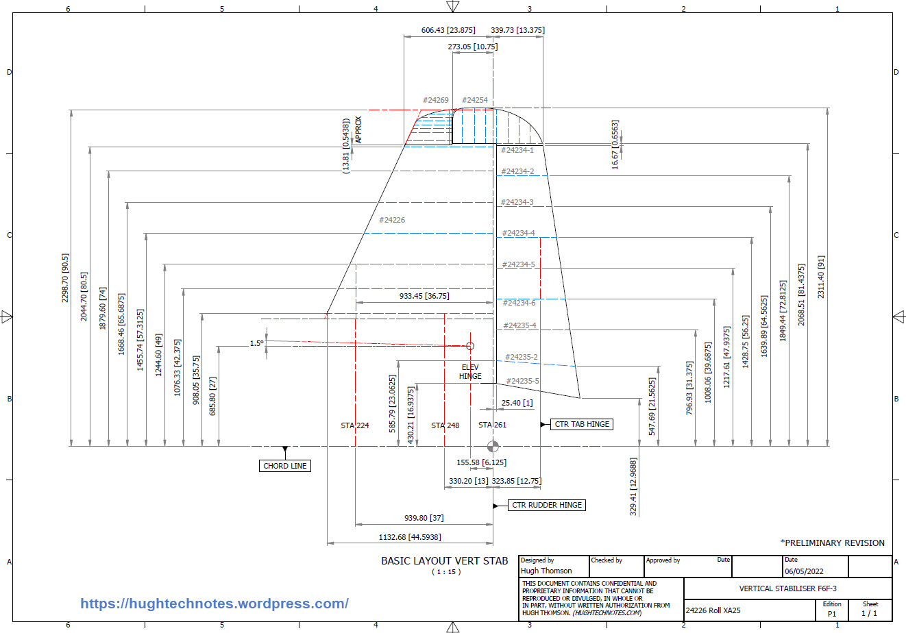
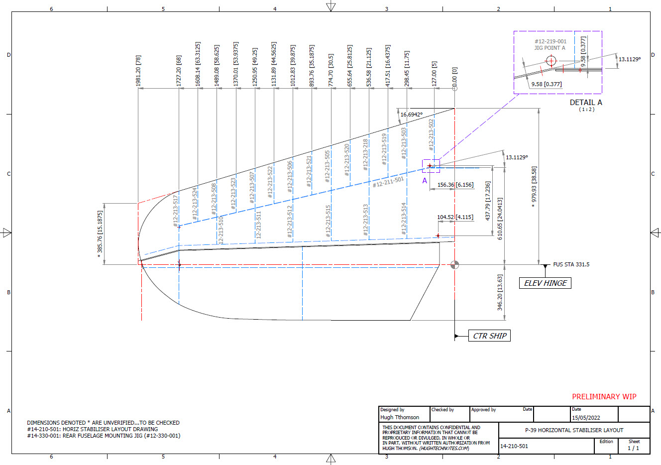
For the last 3 weeks I have been working on an update to the Bell P-39 Airacobra Ordinate and CAD dataset. The original P-39 was intended to be a personal study of the construction and structure and therefore never actually finished. However following a request from a good friend who asked if I could do some work on the Vertical and Horizontal Stabilisers I decided to have a look and see what I could do.
This model is brand new, effectively replacing the old model with a new direction in how these models are presented. The majority of the CAD/Ordinate datasets comprise extensive spreadsheets of dimensional data, drawings and a 3d cad model of the profiles. The idea is that all this data will provide the end-user with a number of options for their own projects. To develop their own models, from either the 3D cad model provided, the 2d drawings or using the spreadsheet data. Fundamental to all this is getting the core dimensions correct which was my primary goal.
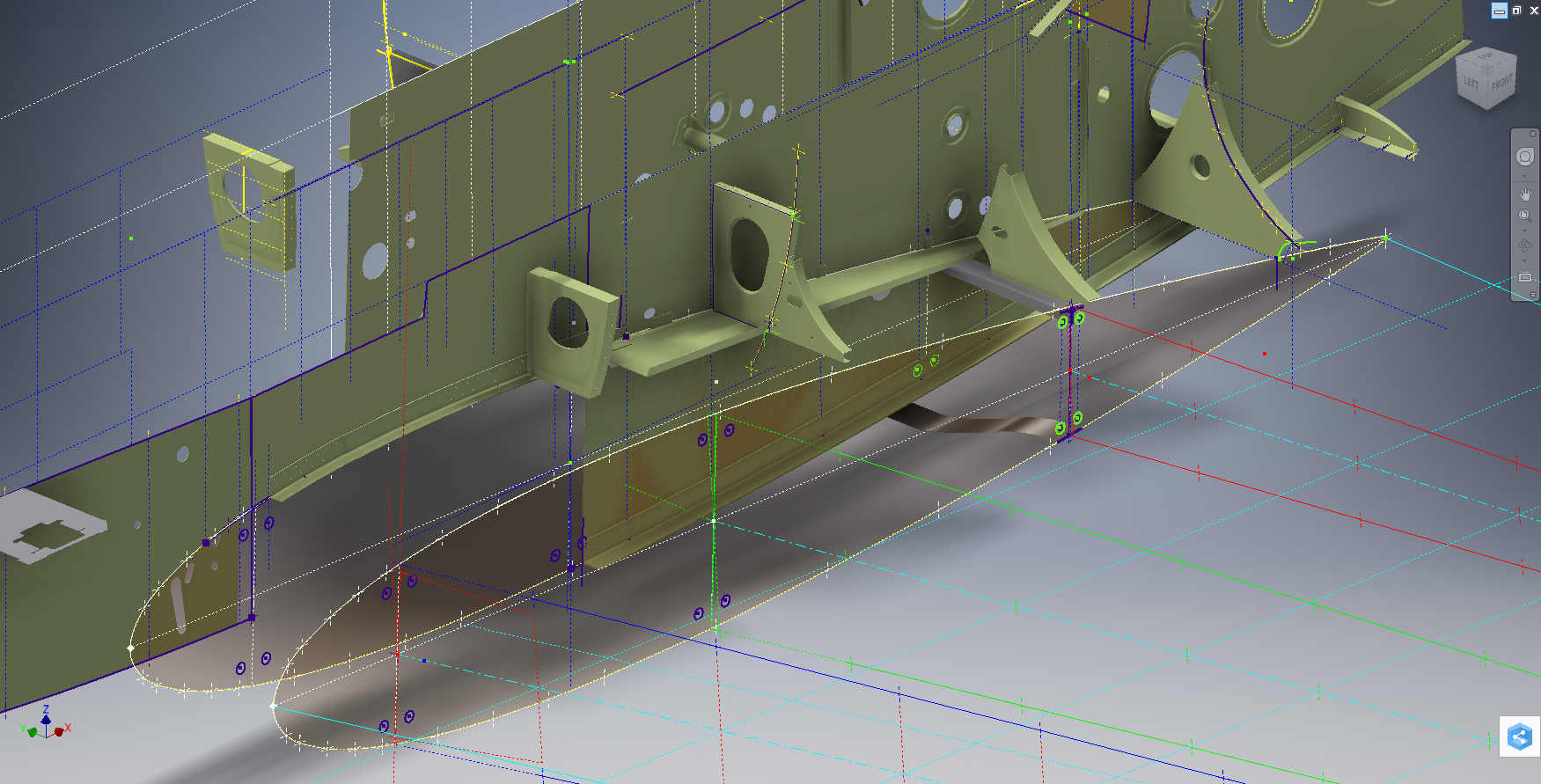
I have extended that concept further by applying a base material thickness to the frames and ribs using the Sheet Metal function. For reasons of clarity it is just the basic web profile but what it does is provide the end-user with an actual solid 3d model; dimensionally correct. This can be further utilised for production or used for RC models with the basic frames in place.
This development came about as a consequence of building the Horizontal Stabiliser. This was hampered due to a number of significant Bell drawings that don’t seem to exist as well as a few-dimensional error in the drawings I do have.
Developing this model required a lot of research to achieve the most accurate model possible for the P-39 Stabiliser. For example, the angle noted at “3” is defined on the Bell drawings as 13 degrees but when you check the layout against the Jig mounting points on the fuselage the angle is actually 13.1127 degrees. The material thickness of the ribs was an important factor when calculating this angle.
The dimension at “1” is not on the drawings but I did eventually find this quoted on a NACA Wartime report which aligns perfectly with expectations. The Leading Edge sweep angle is derived after I developed the LE ribs and aligned with known information. This is close and guaranteed to be within plus or minus 0.2 degrees. I have also written to a few companies that have P-39s to see if they are able to verify this angle. Update: Note the leading edge angle has been verified with a new value; see later post on this blog dated 12 July 2022.
The new P-39 Airacobra model and Excel spreadsheets are now online. Dimensionally it covers all aspects, wings, fuselage and empennage. There is also a copy of the old model which is still relevant.
Old Model (more 3d cad bits):
The plan is eventually to revisit the previous CAD Models for the other aircraft projects and add the web material thickness as I have done with the new study. This adds value to the potential use of these models far beyond what I initially intended.
As usual for more information drop me a line at hughtechnotes@gmail.com
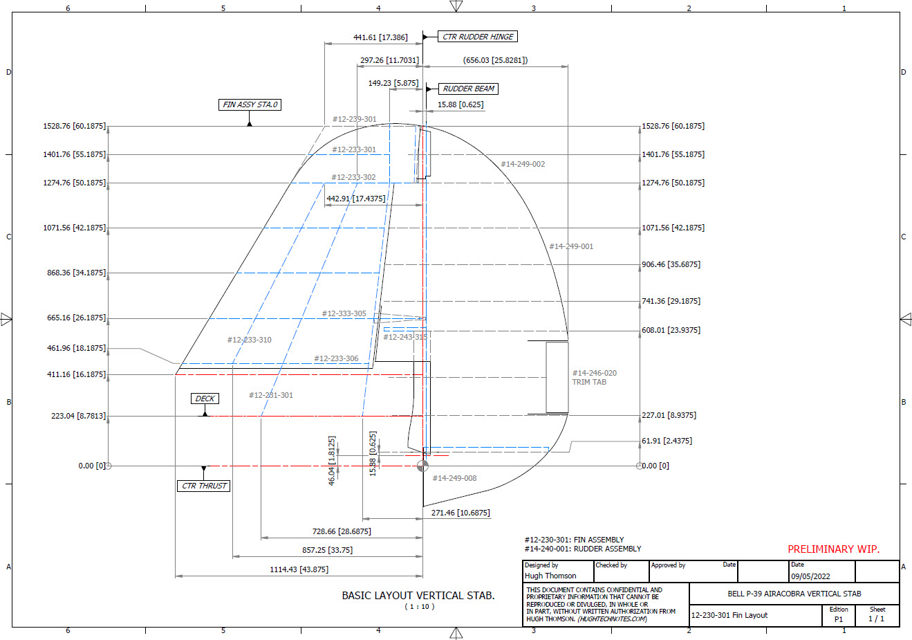
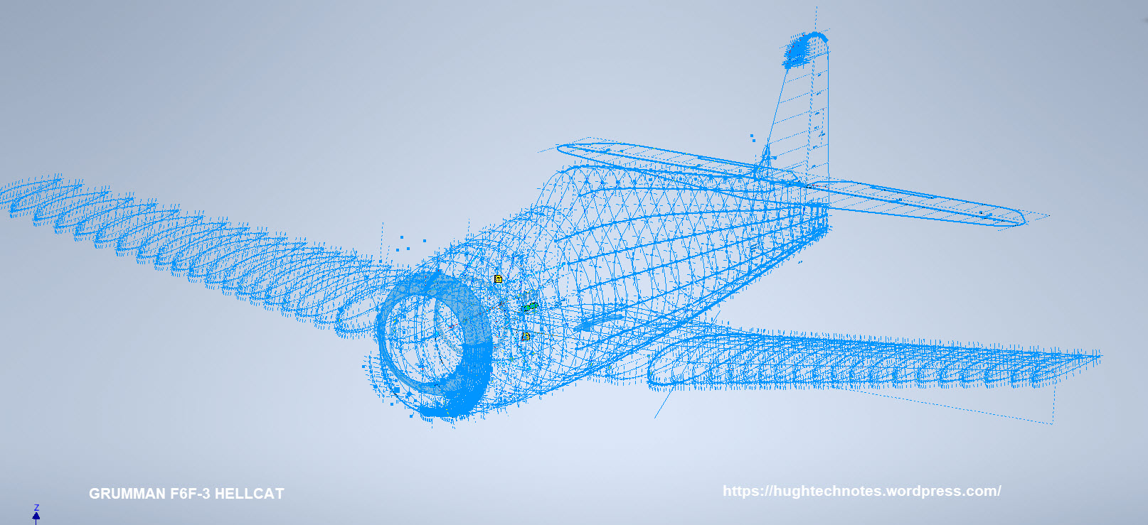
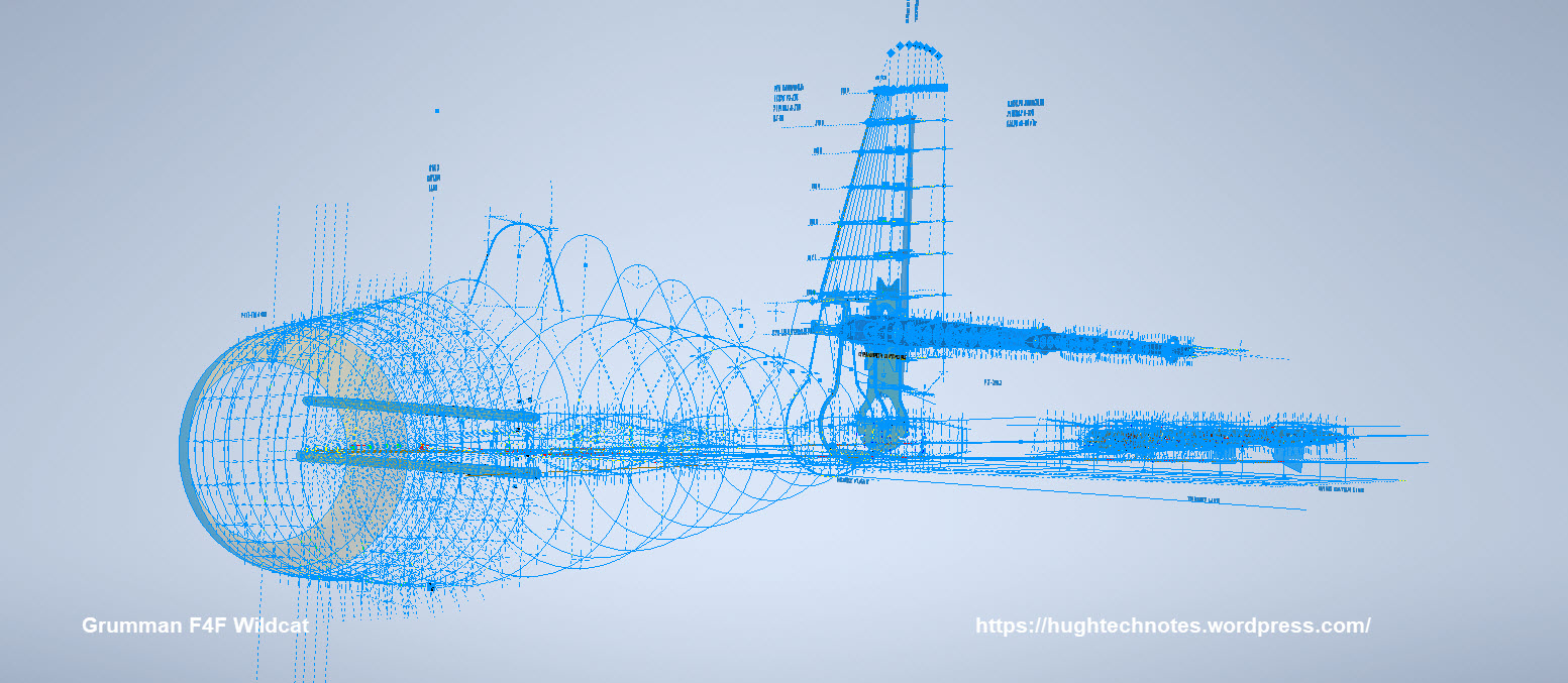
While I source new information for the P-38 Lightning I decided to revisit and update the Grumman F6F Hellcat and the Bell P-39 Airacobra Cad/Ordinate datasets. This work relates to the empennage for which I have decided to make the Autocad DWG and a PDF copy of these documents available for download.
These drawings are preliminary Basic Layouts for early release. The 3D CAD model updates will only be available to those that have previously purchased a copy from me directly. Though these won’t be finalised until nearer the end of May 2022. I shall contact the buyers directly in that respect.
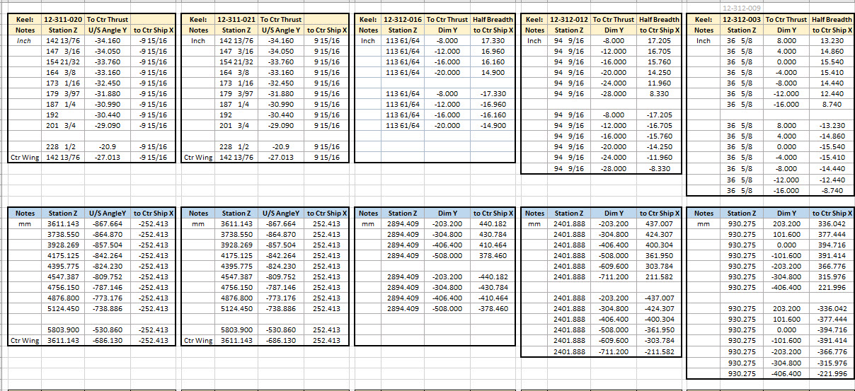
I am also in the process of tidying up the Ordinate datasheets to make them easier to read. The datasheets list the ordinates for each frame/station profile in both Inches and Millimetres with a second sheet that extrapolates this data and compiles the data as X, Y, and Z coordinates for input into any CAD system. These X, Y and Z coordinates have initially 3 columns for each ordinate which is ideal for Mechanical systems like Autodesk Inventor plus an additional concatenate column which combines all coordinates comma-delimited for Multiple Point input into Autocad.
Other CAD/Ordinate Datasets:
These CAD/Ordinate packages are designed to help you kickstart your own projects. All the dimensional research has been done for you, which will save you weeks of work.
For more information drop me a line at: hughtechnotes@gmail.com
Another project that is long overdue is a drawing register for the P-39 Airacobra. This will be an Excel spreadsheet complete with drawing number, description and a link to the actual drawing file.
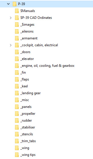
Assuming you have the P-39 folder arrangement as default the links will work fine.
The spreadsheet contains multiple worksheets each designated according to the folder name. The names are tabbed along the bottom to open each worksheet. The links will open the connected file in Adobe Acrobat so make sure you have the Acrobat Reader as a minimum.
The spreadsheet is still work in progress which hopefully will be available for free download this evening. The spreadsheet needs to be deposited in the root P-39 folder.
The spreadsheet is fully editable so you can adapt it for your own project. I should note that columns G and H are temporarily hidden columns that contain the hyperlink address…so don’t be alarmed when they suddenly pop up when you are developing your own adaptations.
To HIDE or UNHIDE a column, select the column header, right-click and select the option from the menu.
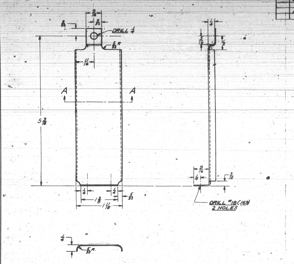
This is a sheet metal part for the P-39 Airacobra (#12-509-052) sent to me by a fellow enthusiast for comment. Before I get immersed in discussion on this subject I would just say that this part is a cable cover that is unlikely to be under any substantial stress and thus would probably be fine as modelled.
The part comprises 2 tabs, one on the top and one on the bottom. It is the fillet radius that I will focus on. The first bend is offset from the edge of the plate. The drawing specifies a 5/32″ (4mm) radius for the fillets at the intersection of the top tab and the main body which overlaps the sheet metal bend. The originator has taken this literally and attempted to create a finished fillet of 5/32″.
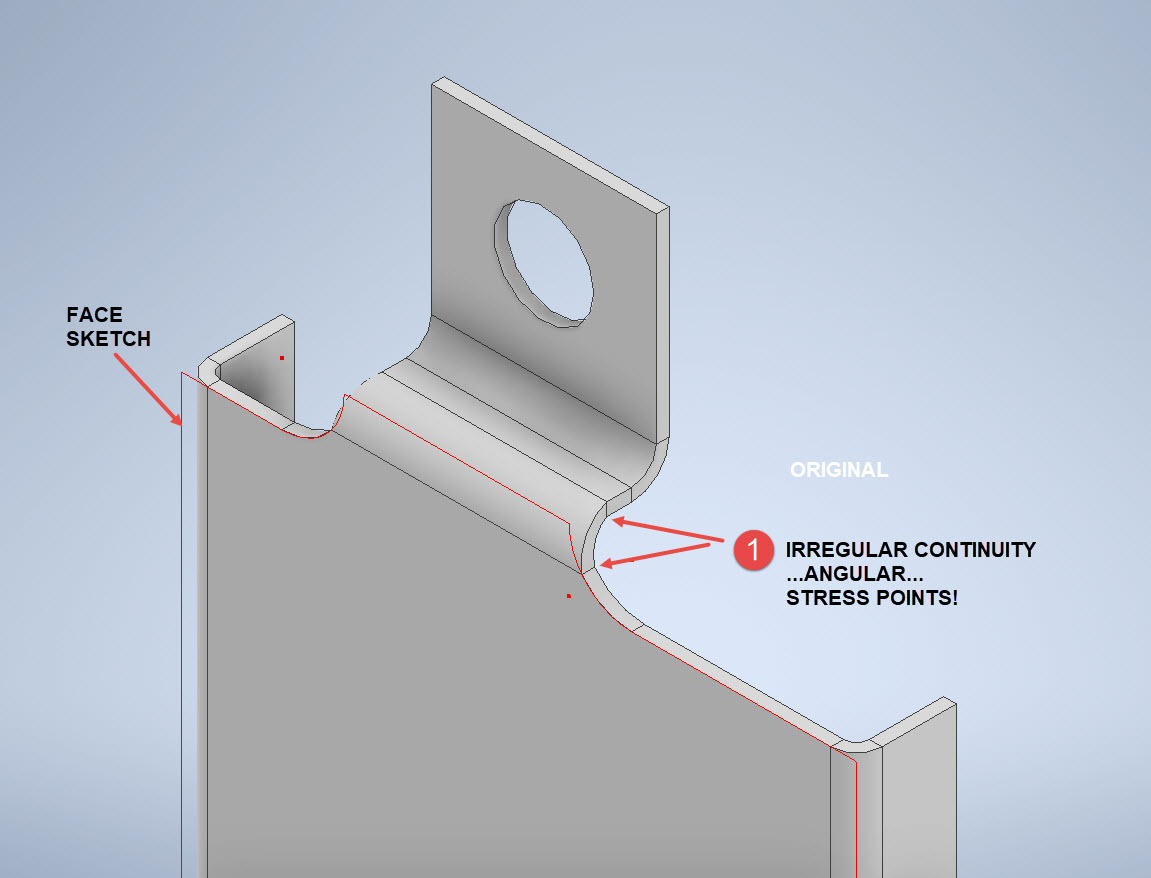
I suspect that the drawing is actually referring to a 5/32″ radius as it would be for the developed flat pattern because doing so otherwise; due to the bend being offset as illustrated on the cad model; this introduces stress points.
The images show the irregular continuity which creates angular edges that essentially become focussed stress points. It is often best to try to achieve smooth continuity both for bending purposes and of course when in use. What they did was sketch a face profile; which included the specified radius (#1)and then proceeded to adopt the standard commands to build the flanges. Technically it is not wrong but as the manufacturer’s drawing does not contain a developed flat pattern it is often misinterpreted…the radius should perhaps be applied to the pattern before bending.
Similarly, at the bottom tab, we also have irregular continuity as shown at #2.
I rebuilt this model to address these issues and you can see how a small change in modelling technique can obviate some of these issues.
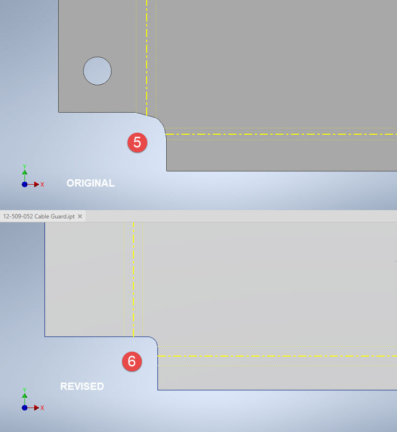
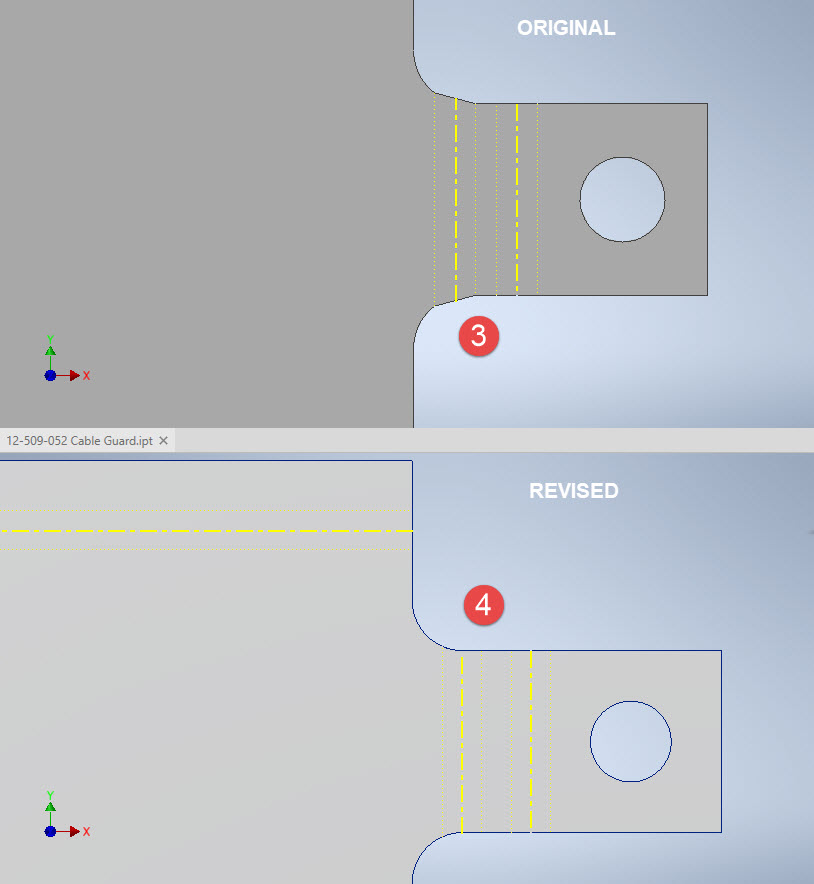
The images show the developed pattern with the original cad model on the top and the new version on the bottom. At #3 the outline of the tab would be difficult to cut with the small taper before the fillet, whereas the lower profile at #4 is easier to cut with no stress points. Similarly for the base tab at #5 and #6. I should note that the bottom tab radius is not specified so I opted for the default minimum which fits nicely before the bend lines.
There are several ways to do this with the easiest being accomplished by using the Unfold command on a square flange and then applying the fillet before refolding. The option I have used here is first to draw an extended flange as part of the initial face sketch, create the first part of the model as a Face then apply the 5/32″ fillet before bending along a predetermined bend line sketch.
The sketched tab outline is a lot bigger than is required which of course can be trimmed once the tab is complete. You can see the extents of the tab on the initial sketch…you only need to add a plane at that point to trim. The resulting fillet is a smooth continuity with no obvious stress points.
Understandably the designers wished to increase the amount of material at the bend to maximise strength so it is advised to try to achieve those goals. As I said before, for a cover like this it is probably not too critical if we only applied a small fillet but for framing and structural elements, it may be critical.
One quick note on the 2 vertical flanges…the drawing specified an internal radius of 5/32″ which to be honest is unworkable as the resulting bend would overlap the bottom tab…in this case, I opted for the minimum specified.
At the end of the day, it is down to the interpretation of the designer intent. For the majority of sheet-metal drawings, they often do not include developed flat patterns but may contain information that is actually applicable to the flat pattern and not necessarily the finished folded profile.
“SIMFEROPOL, September 25. / TASS /. An expedition of the Russian Geographical Society (RGO), together with the Russian Ministry of Defense, lifted a Bell P-39 Airacobra fighter from the bottom of the Black Sea from the regiment that took part in the air cover of the Yalta conference of leaders of the anti-Hitler coalition in 1945, a specialist from the Expeditionary Center of the Ministry of Defense Anatoly told TASS on Friday Kalemberg.”
As many of you know I am a huge fan of the P-39 Airacobra. So I was particularly interested to read these reports of the recovery of this P-39 from the Black Sea. These are the links to the articles I have read so far from various news publications.
If anyone has any further information to share on this project please drop me a line and I will feature updates in future articles; perhaps even progress on the restoration.
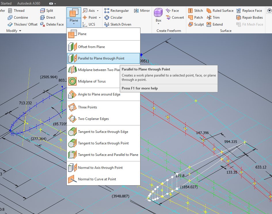
This is one of those instances where you do something on a regular basis and don’t really appreciate the significance of the process. What I am referring to is when you create a sketch Plane using the option “Parallel to Plane Through Point”.
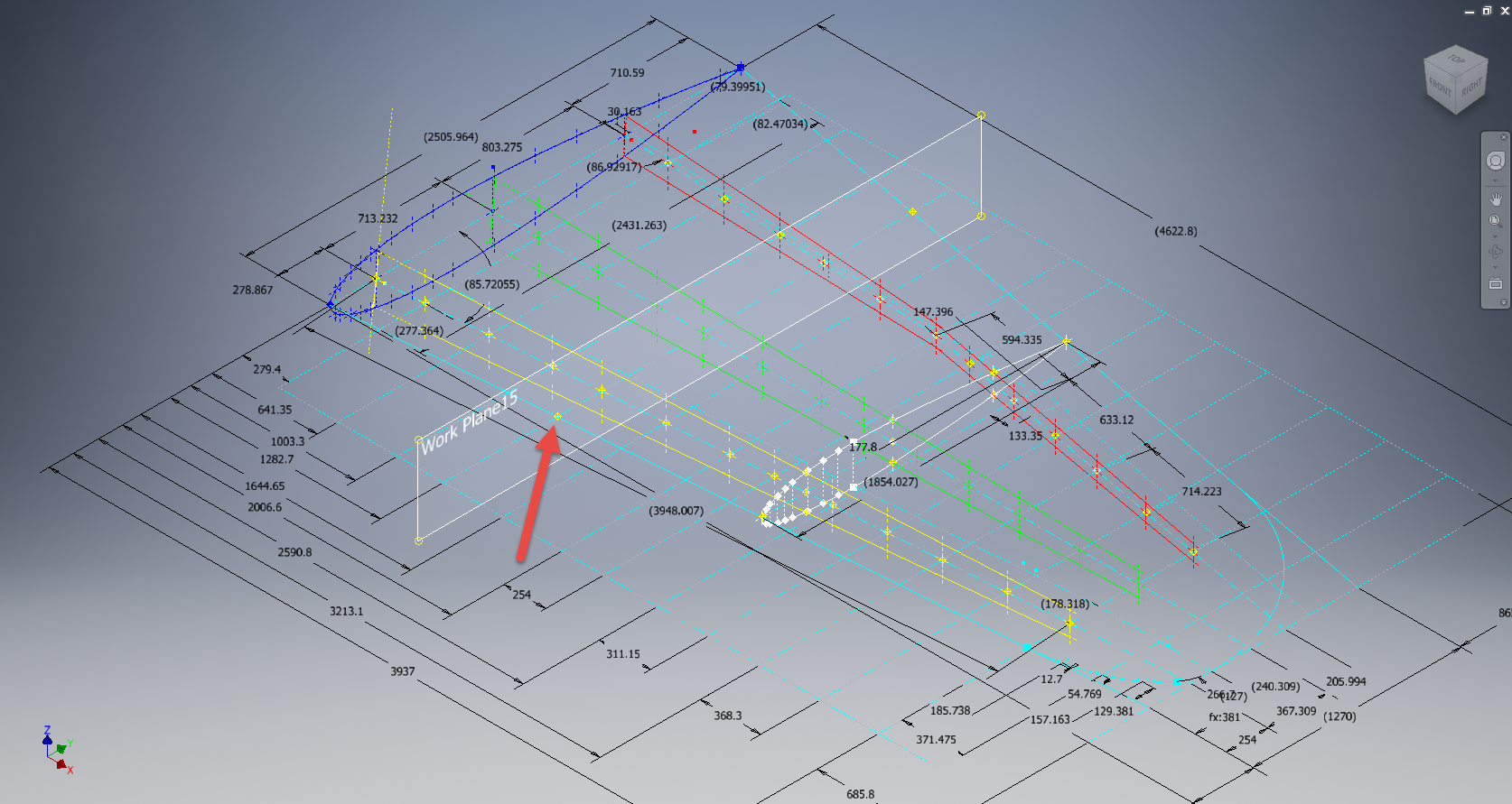
It transpires that this selected point becomes the datum for the particular sketch created on this plane. For this example, for a P-39 wing rib, we have selected a point for the Plane location along the wing leading edge as shown.
The Bell P-39 and similarly for the P-51 Mustang the wing ordinates are set out from the leading edge of the wing so it makes sense that the rib sketch is setup with a suitable datum point. You can tell the location of the temporary datum in the sketch applied to this plane by the position of the main axis.
This is the really interesting part, when you now import a set of points from the Ordinate spreadsheets it will recognize this sketch datum and import the points relative to this point irrespective of the model origin.
This is very useful particularly for these aircraft projects as we tend to use a lot of ordinate data for the outline geometry.
Another Quick Tip:
To automatically apply a tangent constraint to a sketch line just select and drag the line from an existing line and the tangent constraint will be applied.