Technote: Rivets:
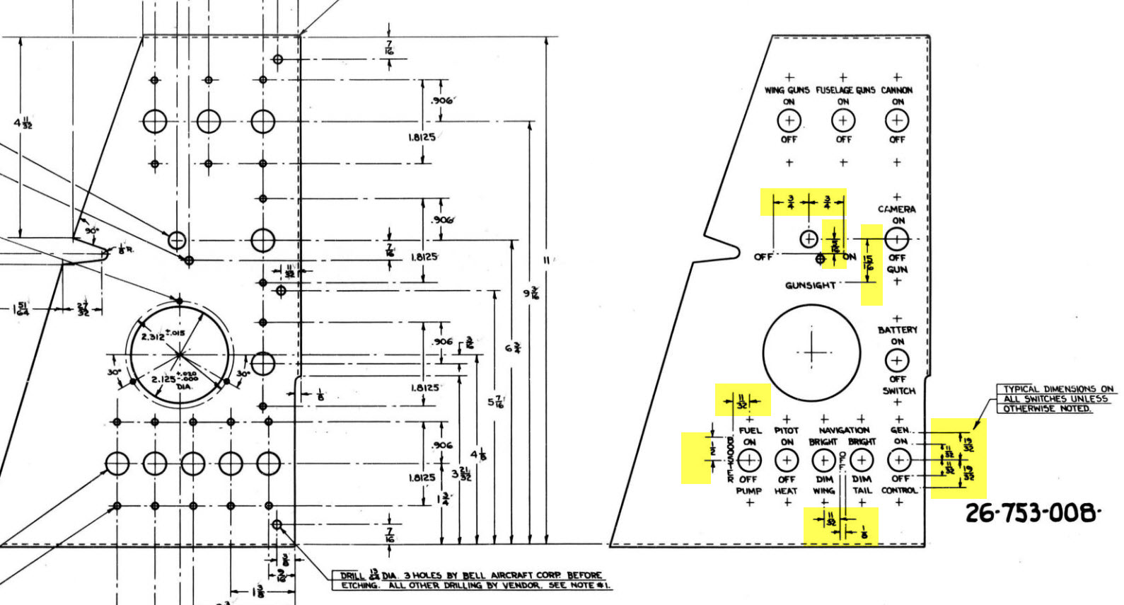
Developing the CAD standards for Rivets has been on my to-do list for far too long..so with the progression of the P-39 cockpit instruments it has become a priority. Typically on the Bell drawings and other aircraft manufacturers’ drawings we may only have the hole sizes noted, the rivet designation or information pertaining to the same but unreadable. Also occasionally even when we do have the hole sizes and the rivet designation often we don’t have the length required.
Something needed to be done to make this task a lot easier, particularly when you have instrument panels that incorporate many different types and sizes of rivets.
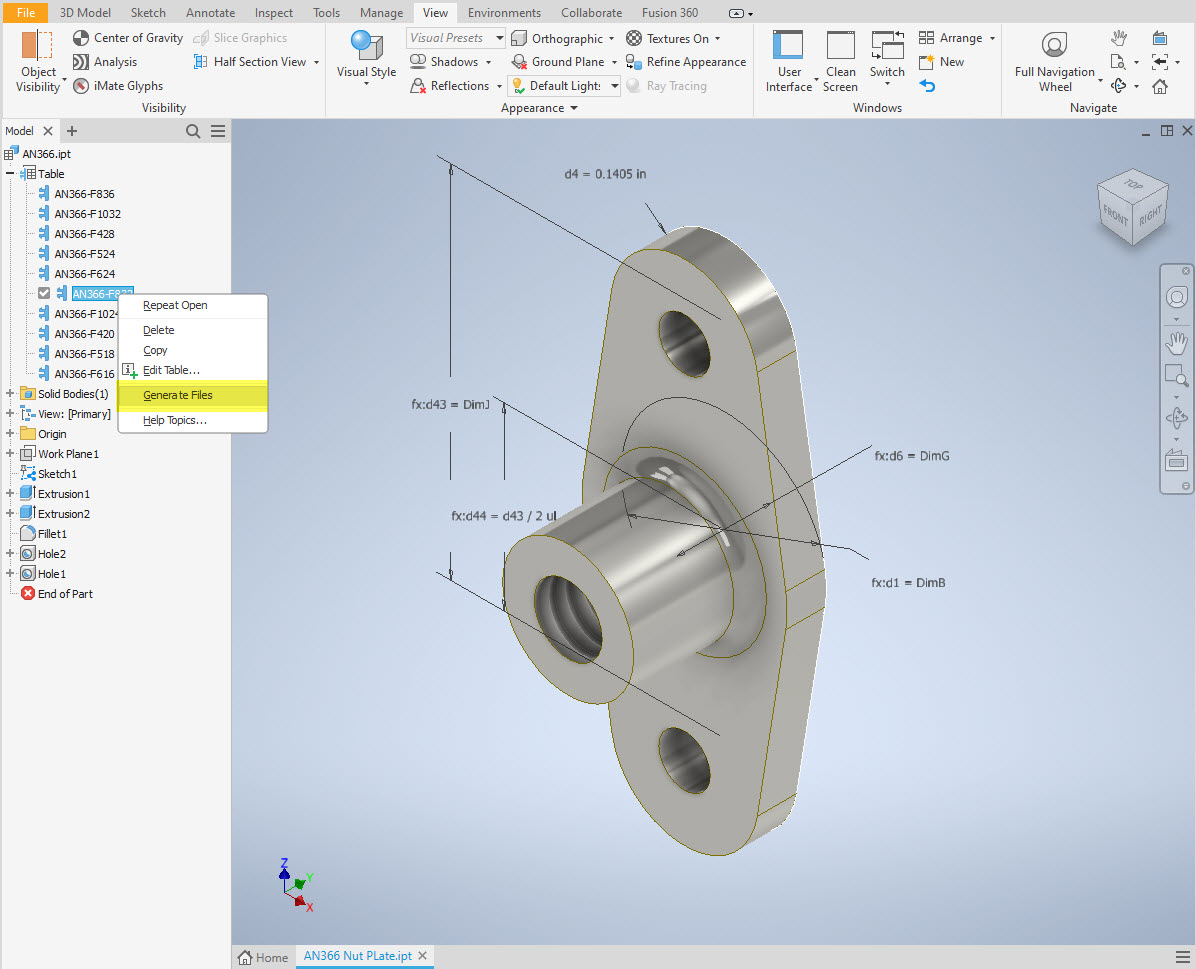
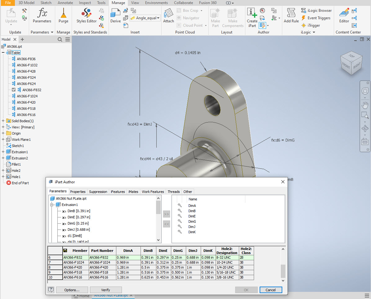
The first part of the process is to create several parts for the various types of rivets; which at the moment are listing the most common sizes I need right now. You will notice that the Rivet Name does not include the material type as doing so would require an extraordinarily large table of data. So the name is simplified to make this task easier to correlate but also because the priority at this time is dimensional correctness for rivet type, diameter, hole sizes and rivet length. At some stage, I will invest some time into deriving the various information sources to correctly name the rivets according to the AN and MS standards.
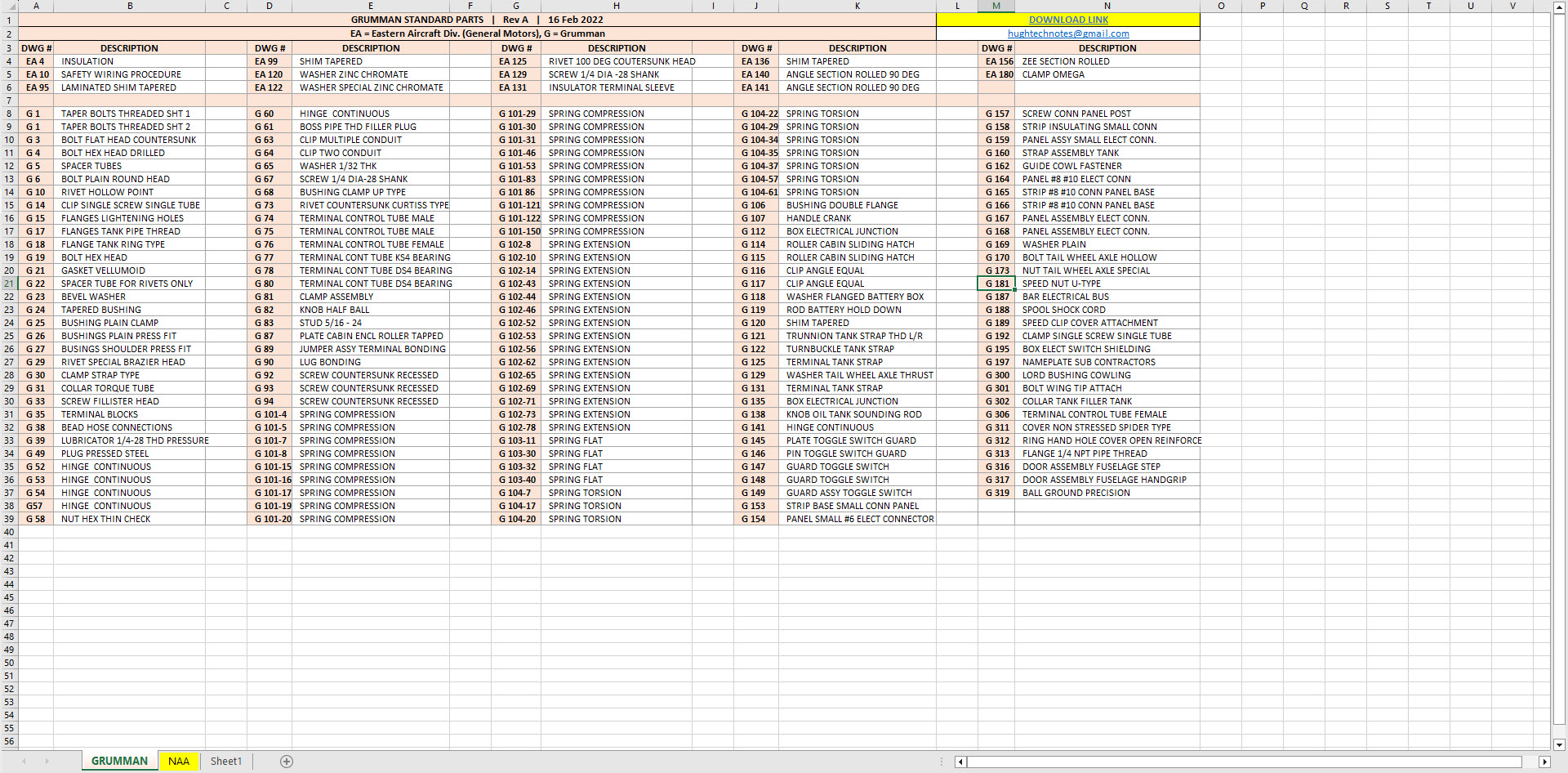
To complement the CAD iParts I also have a few spreadsheets listing key parameters and fabrication criteria.
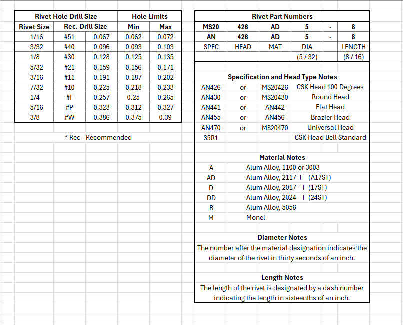


The above tables are self-explanatory with the inclusion of a designation for a Bell Standard Rivet 35R1. I have actually found dimensional information for this type which I will include in the CAD library. This is where things get interesting because of the scarcity of historical components that may no longer be available, it may be necessary to find suitable alternatives.
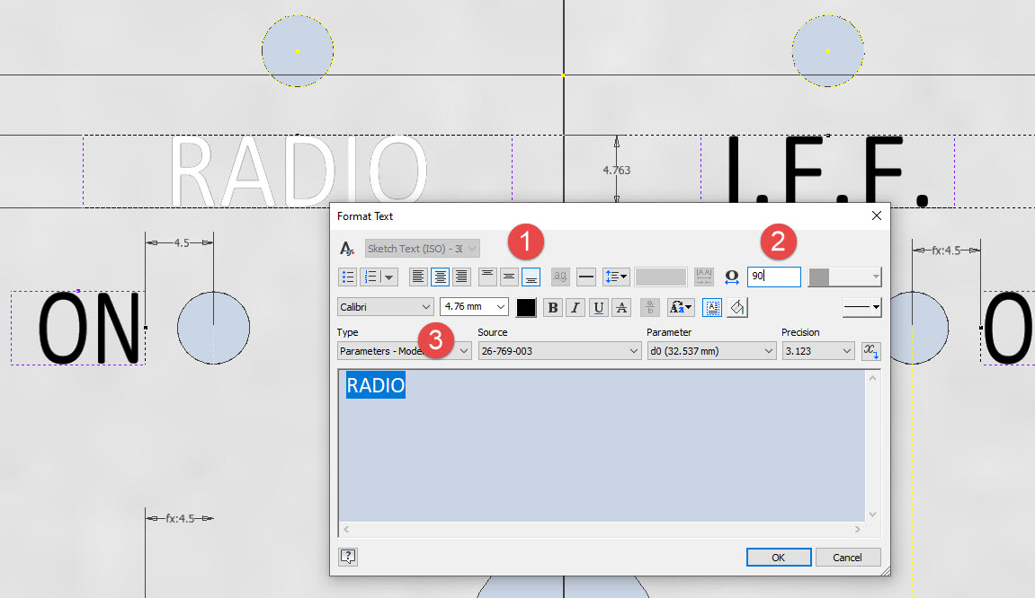
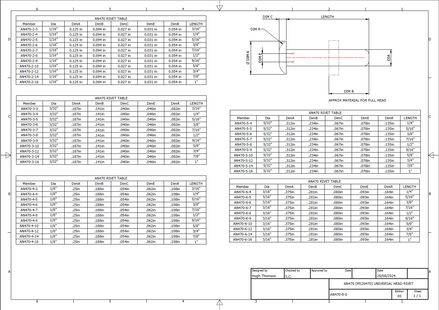
You will notice that the Rivet Grip tables are in inches and mm…as I tend to work using metric mm templates (although the dimensions are input as inches) it makes it easier to measure the material thicknesses in mm and determine from that the rivet length. There is a technote somewhere on my blog that describes the process of inputting inch dimensions in metric mm templated models.
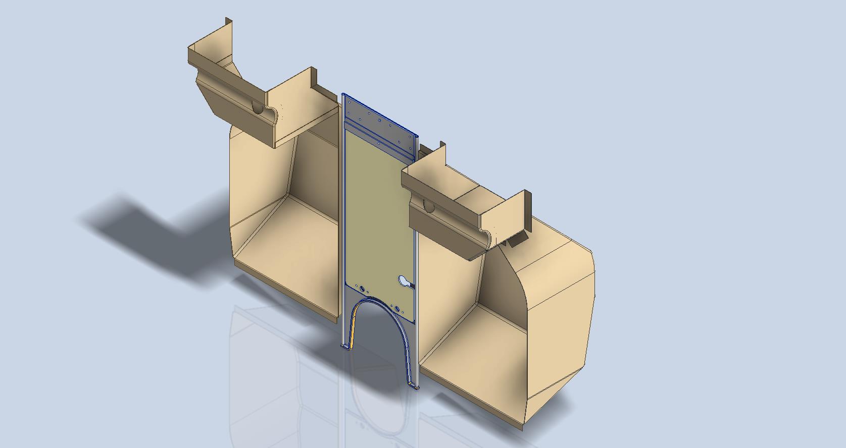
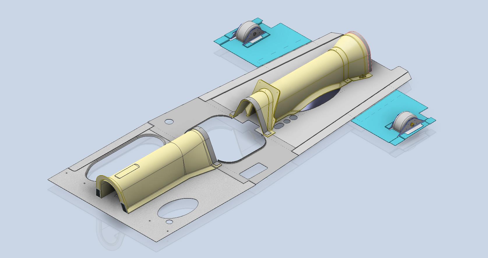
This will be an invaluable asset moving forward with the cockpit rebuild on the P-39. For example where there are issues with the legibility of key information on the Bell assembly drawings I can refer to other connecting part drawings that may only have hole diameters but will be sufficient to determine the correct rivet type and size.
This is very much a work in progress and will be updated as needed.
Update: 28th August 2024:
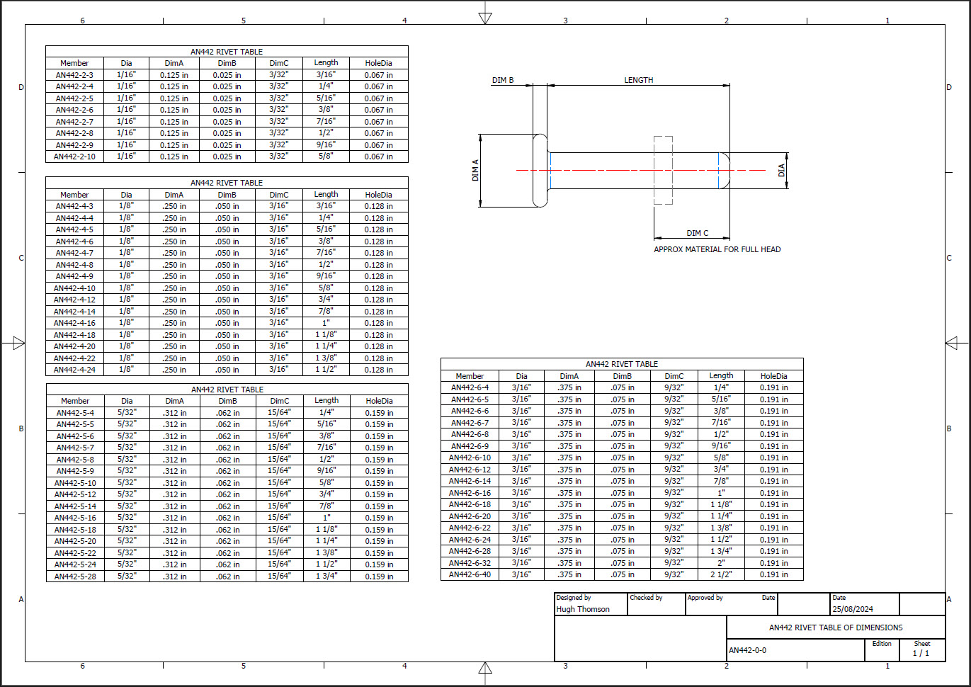
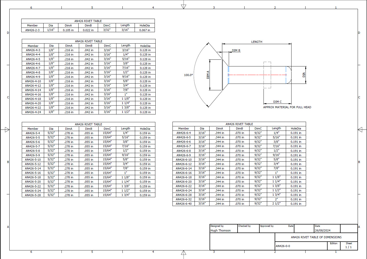
I have updated the Rivet CAD files which now include AN426, AN430, AN442, AN470 and of course the Bell standard 35R1.


All Rivet CAD data files (iParts) are now included in the CAD Standard library (see CAD resource tab for further details) along with original spreadsheets of Rivet Grip and general details.