Goose Bumps!
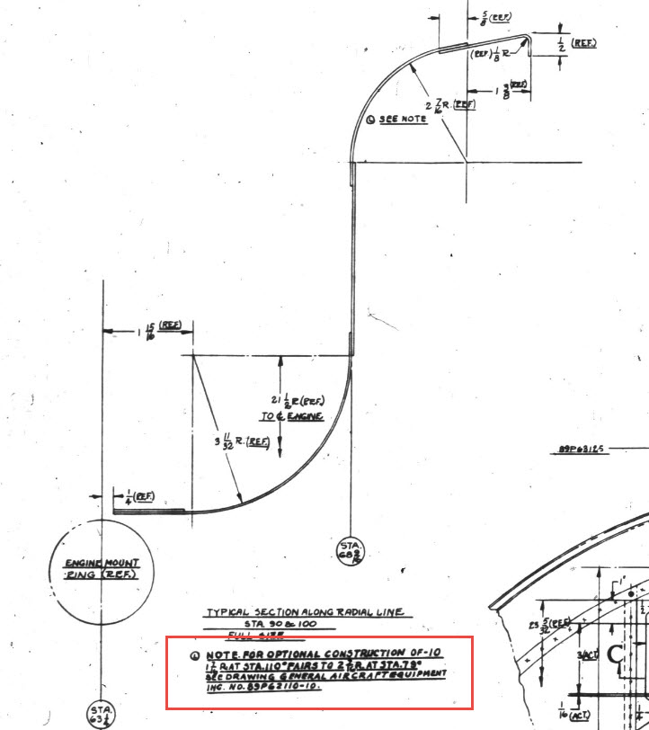
The Grumman Goose project is both challenging and frustrating; it is definitely not a straightforward aircraft to work on. I have primarily focused on updating the empennage, which includes the vertical stabilizer, horizontal stabilizer, rudder, and elevator. During the development of the ordinate study, I observed discrepancies in the documented locations of various components. Let me explain what I mean.


Upon reviewing the CAD drawings on the left and comparing them with the Maintenance Manual diagram, I noticed that the level of the ribs varies by 1/16 of an inch. This discrepancy caused me immediate concern, and I began to wonder where I might have misinterpreted the Grumman drawing data. Therefore, I felt it was necessary to review and verify the information.
Initially, we do not have any reference location information on the Rudder Layout drawing. Normally, you would expect reference dimensions to the fuselage centerline or a fuselage station reference, but there are none. We do, though, have locations of the Hinges on other drawings for the Station bulkheads and Fin layout which in turn will help derive location information for the Rudder.


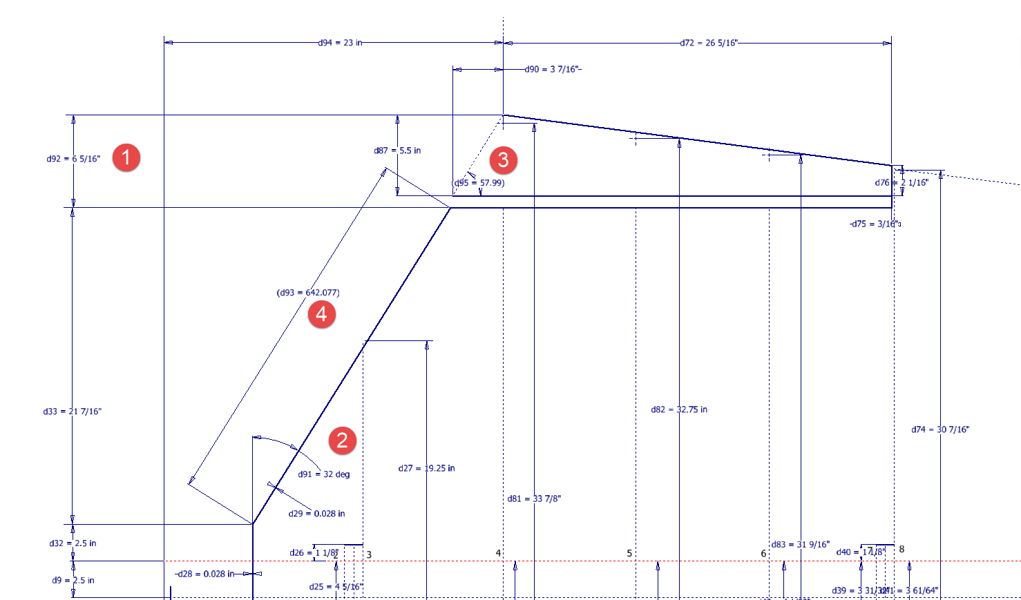
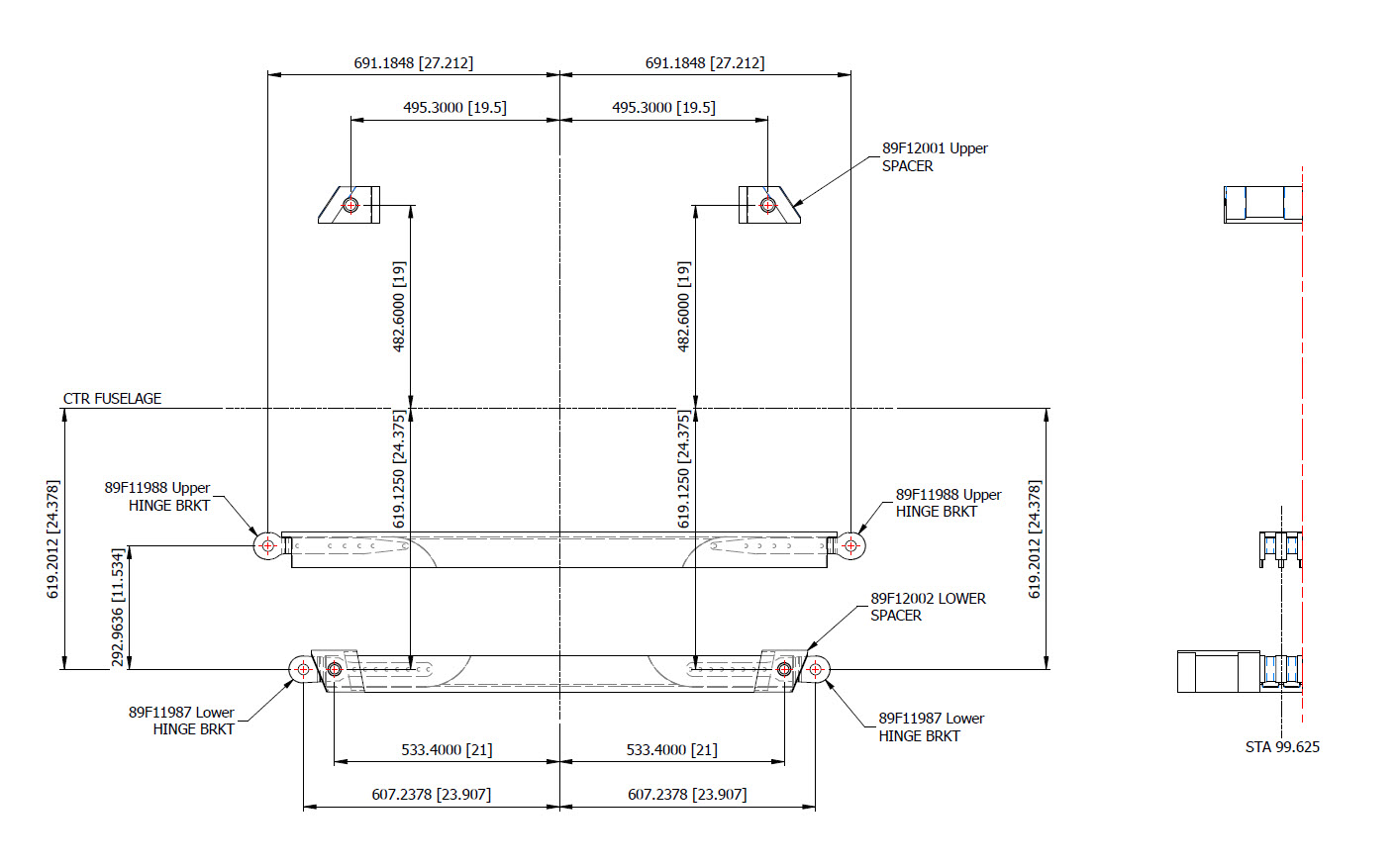
The first image above is the bulkhead layout at Station 36, which specifies the centre of the hinges 1, 2, 3, and 4 relative to the Fuselage Ref Line.. The second image is the bulkhead at Station 33, which shows the dimension of 65 13/16″ to the top of the Lower Rib on the Vertical stabilizer Fin.
I am looking to verify the dimensions and locations of the rudder ribs and hinges in relation to the Fuselage Reference Line. To accomplish this, we will start with the information we have and determine what additional information we need. The first image confirms that the CAD drawings for the rudder accurately depict the positions of the hinges. The second drawing further supports this; the “Top of Rib” location refers to the lower rib of the fin which includes the locations of the hinge centers. At this point, we have established the correct locations of the rudder hinges from two different sources.
Having determined the hinge locations, we know that the ribs for the rudder are offset by 5/8″ on either side of those locations, which allows us to derive the final levels noted on the Rudder Layout CAD drawing. Does this mean that the Grumman drawings, and therefore the CAD drawings, are correct while the manuals are incorrect? Yes and No…let me explain…
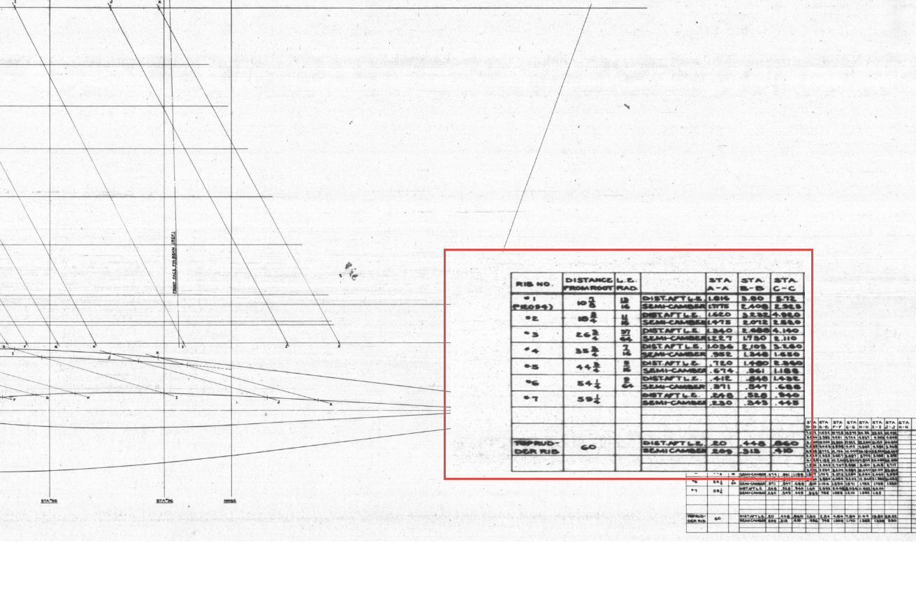

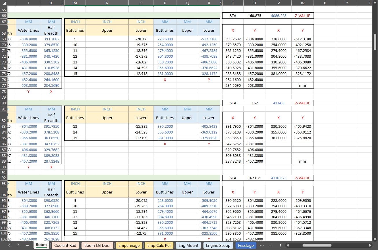
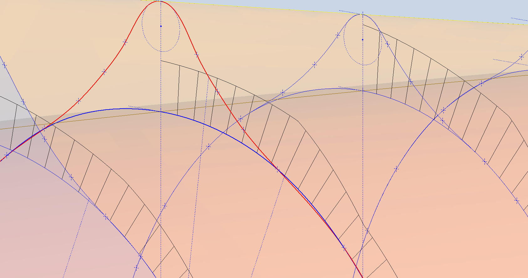
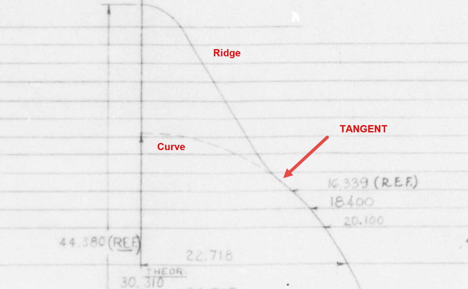
The first image is the Lines Diagram for the Vertical Stabilizer Fin Ribs. In the Table of Offsets, you will notice a list of dimensions from the “Root,” with the first rib specified at 10 7/8 inches. If we overlay these dimensions onto the CAD drawing, we observe a 1/16-inch discrepancy to the top of the first rib. However, all other sources, including those mentioned above and additional references not listed, such as the fuselage Lines layout, indicate that the top of the rib is correctly positioned in the CAD model (second image), contradicting the information provided in this Table of Offsets.
So what is going on?
We should take into account the revision history of the Grumman Goose development. If you examine their drawings, you’ll notice that they have made numerous revisions, some of which are labeled with letters as late in the alphabet as “R.” That indicates a significant number of changes.
I believe that various details have changed over the year, with the more prominent aspects being updated while the less prominent drawings remain unchanged. Regarding the manuals, it seems they were created early in the project, and it may have been considered too labor-intensive to update the level references. This aircraft is quite complex, and I can only imagine the effort involved in both its development and the ongoing updates to its design.
Whenever a small anomaly becomes apparent, I will make an effort to gather information from other drawings to verify the final result. This is one reason why these Odinate studies take so much time; it is crucial to ensure that the final study represents the most accurate dataset possible. If I were building a Grumman Goose replica, I would be using my datasets.
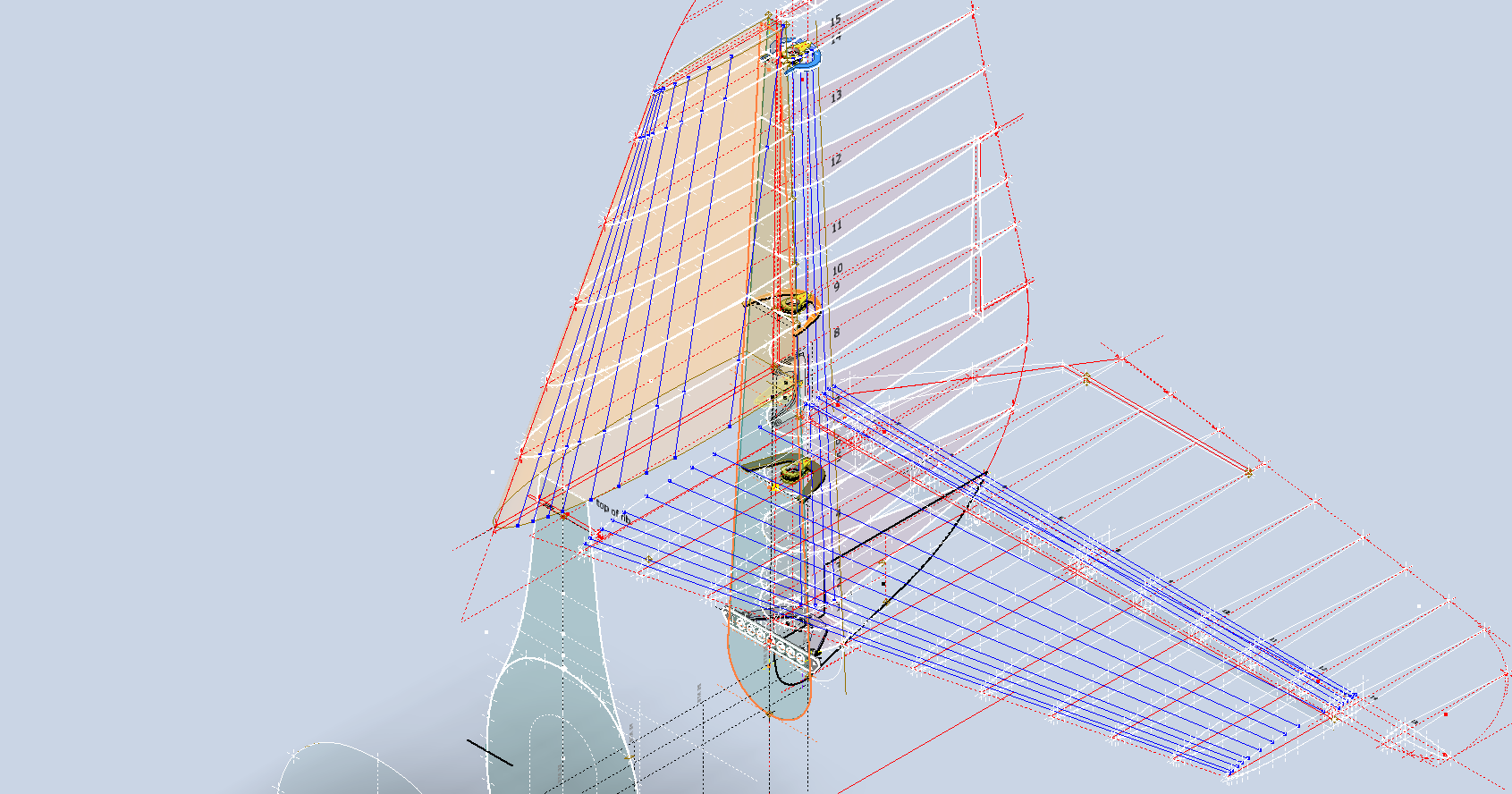
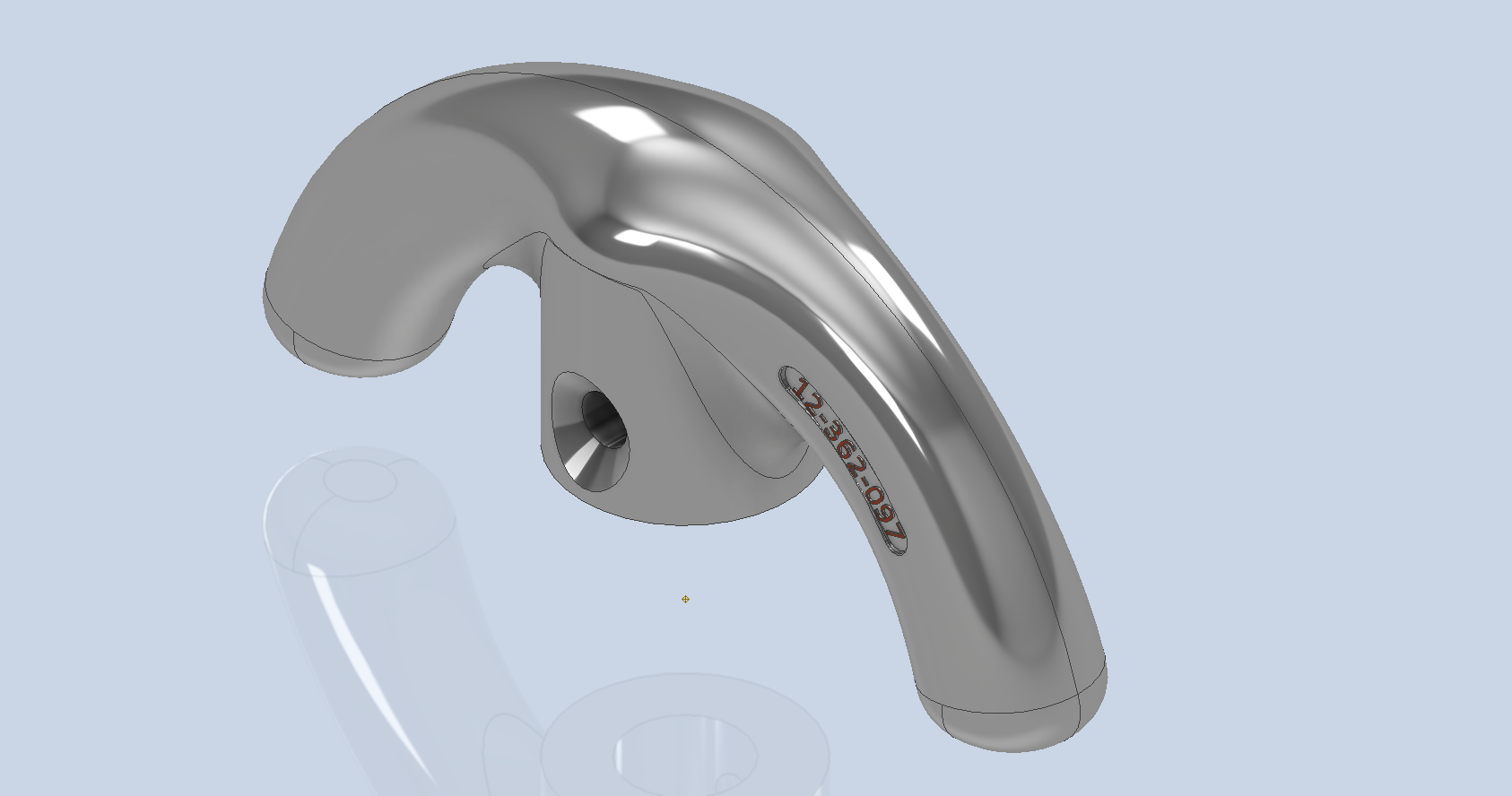
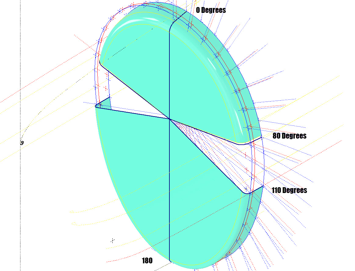
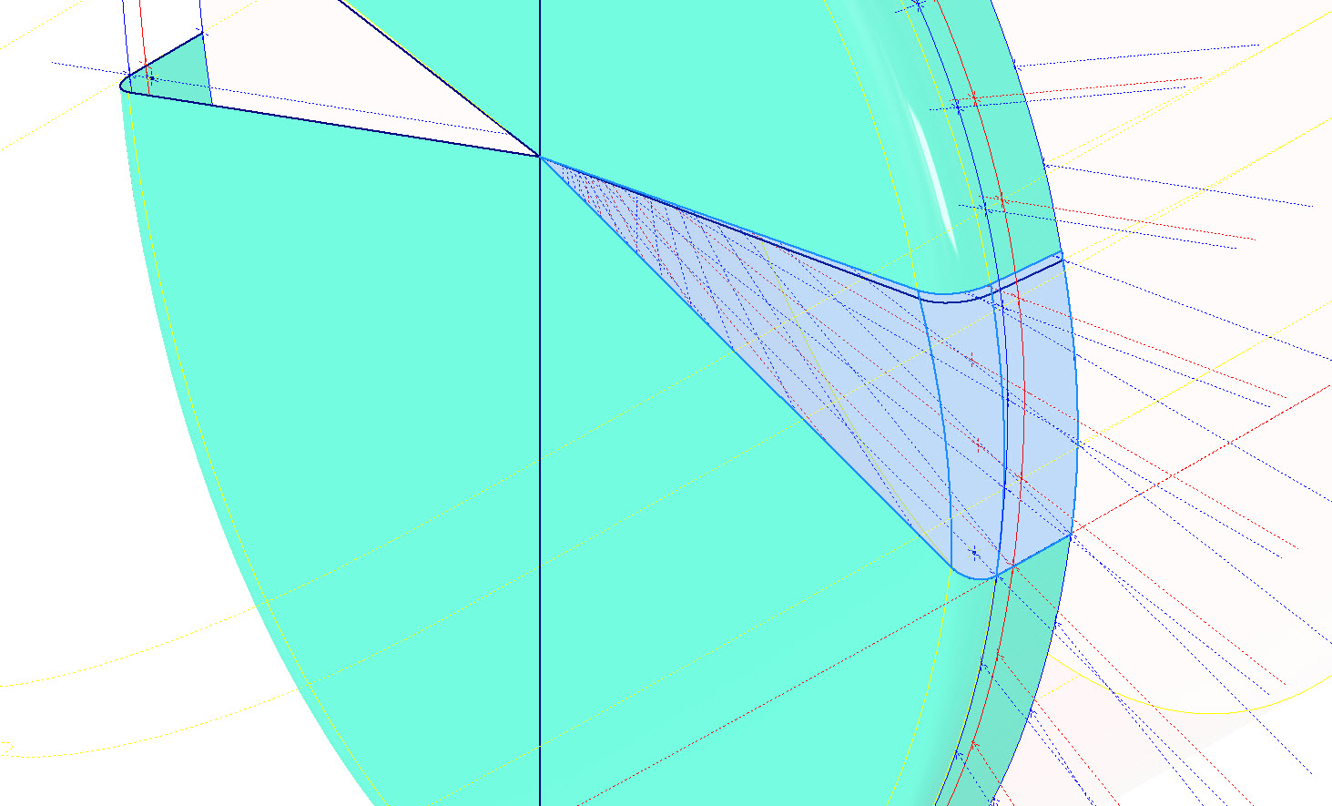
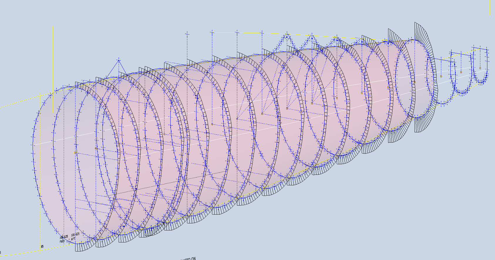
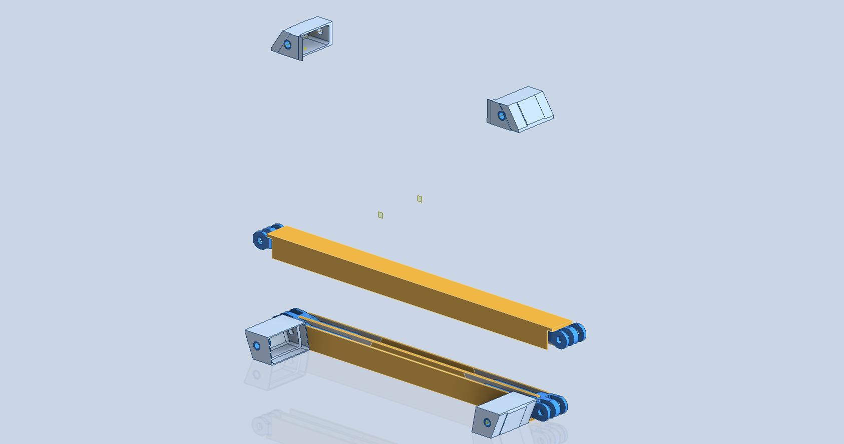
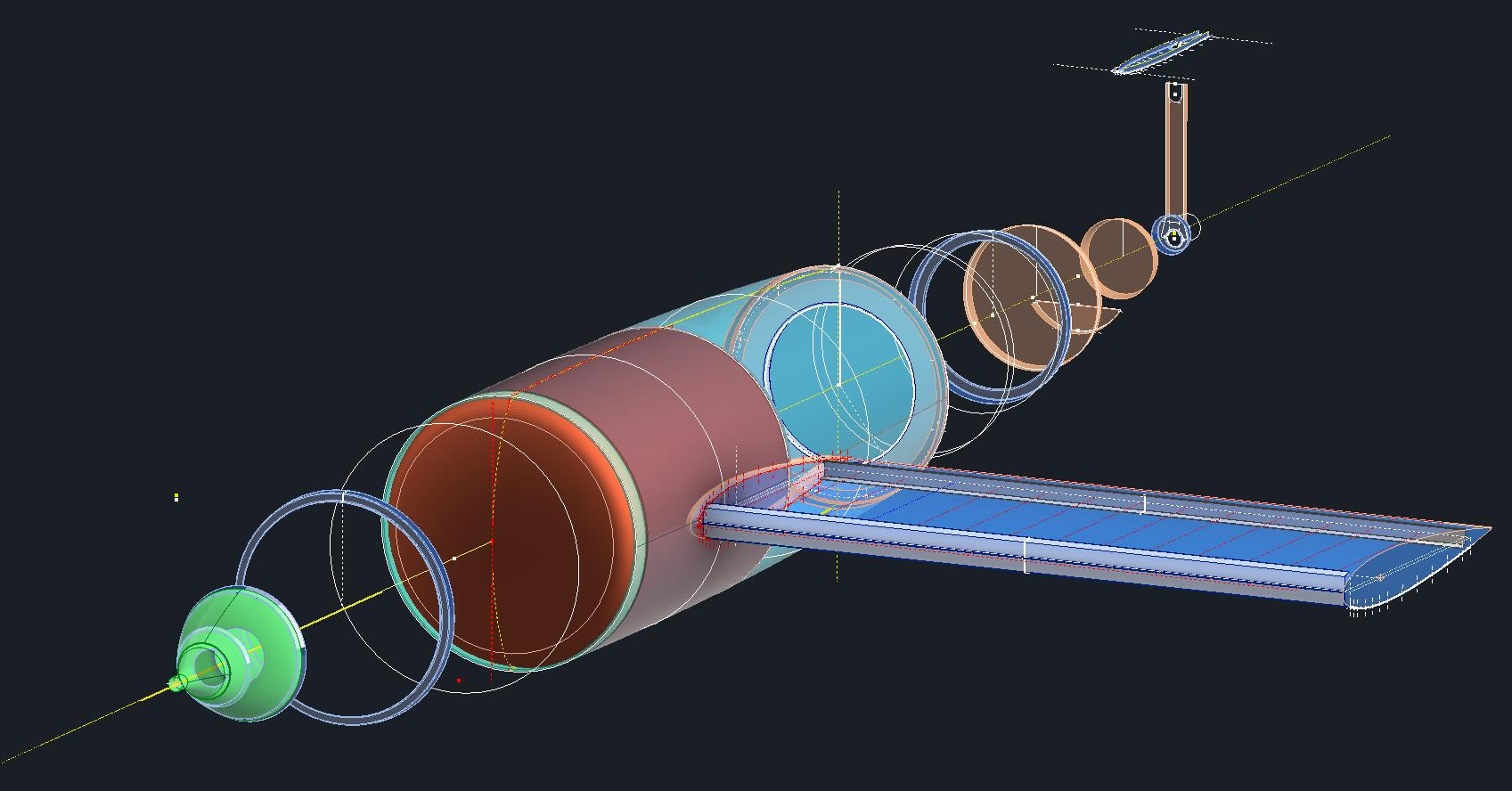
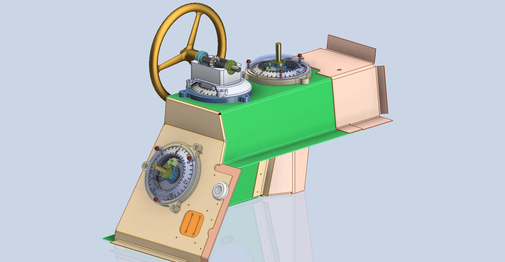
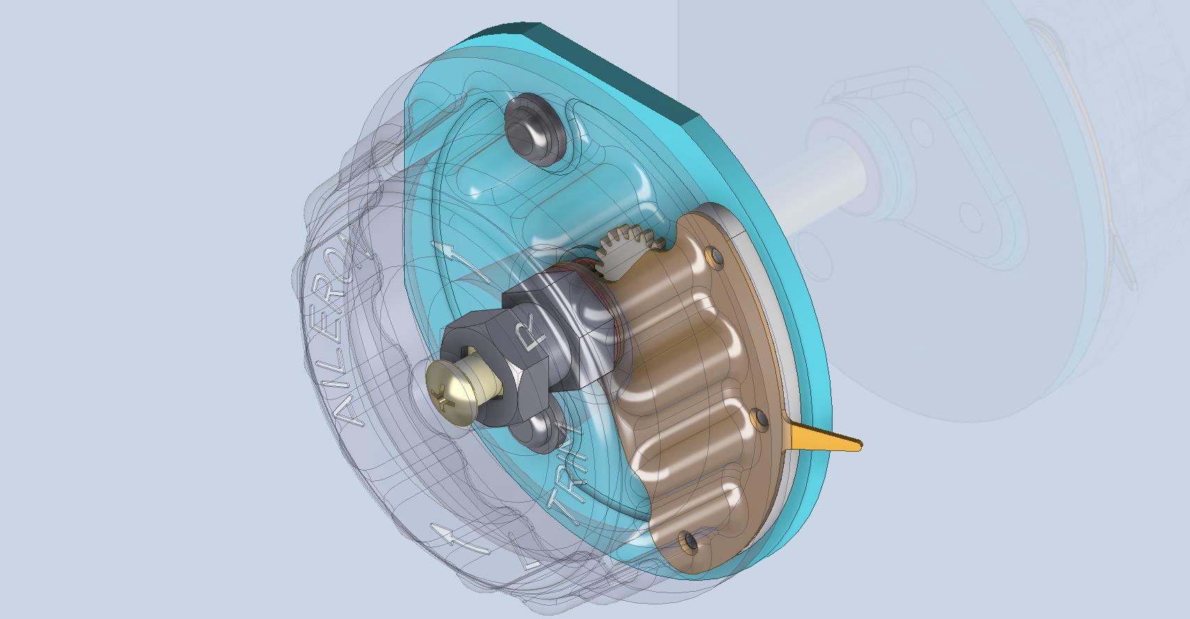
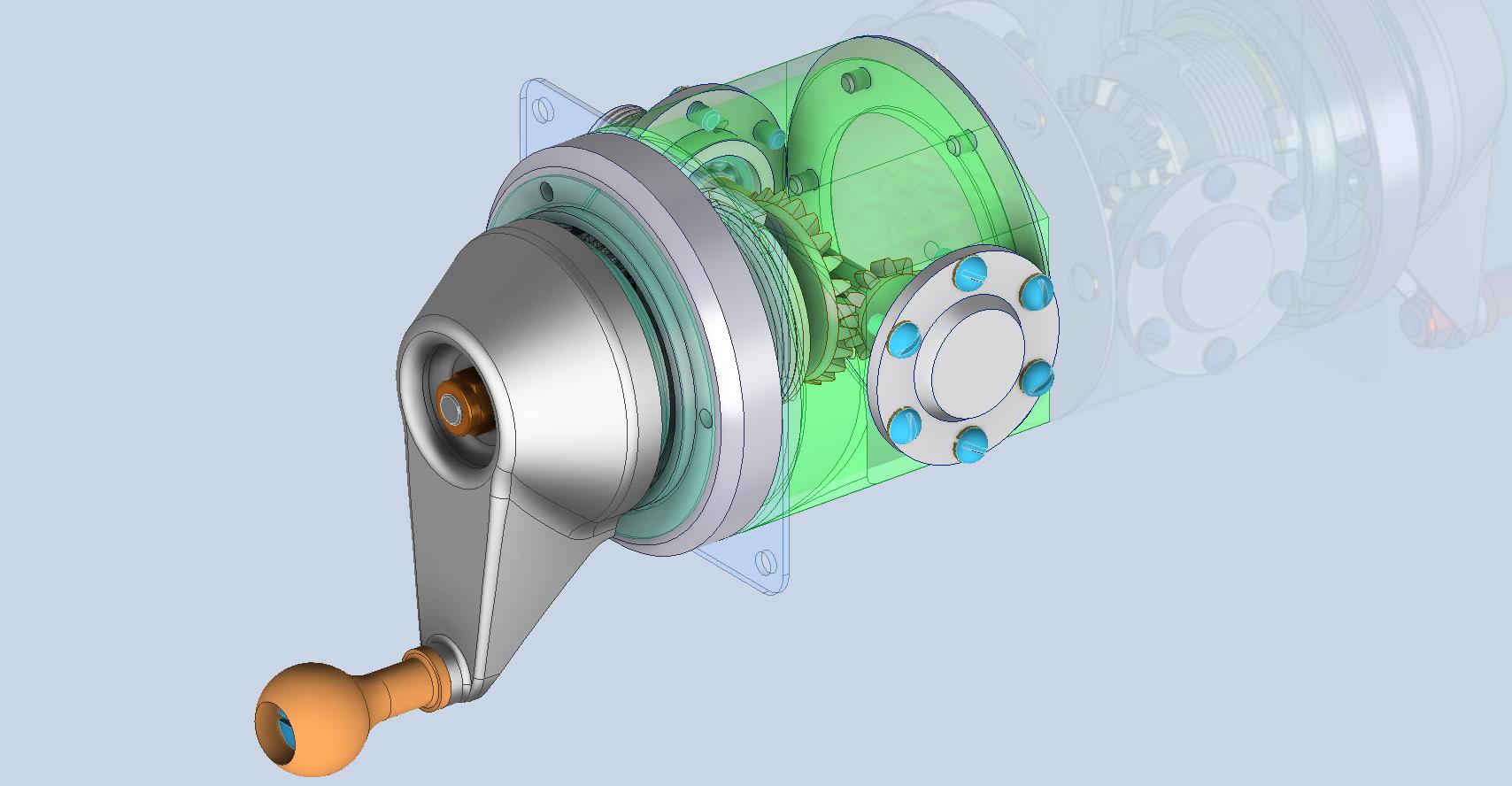
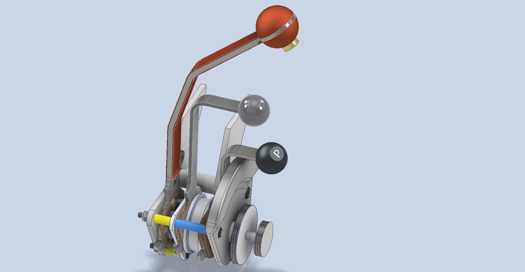
Progress Update 18th March:
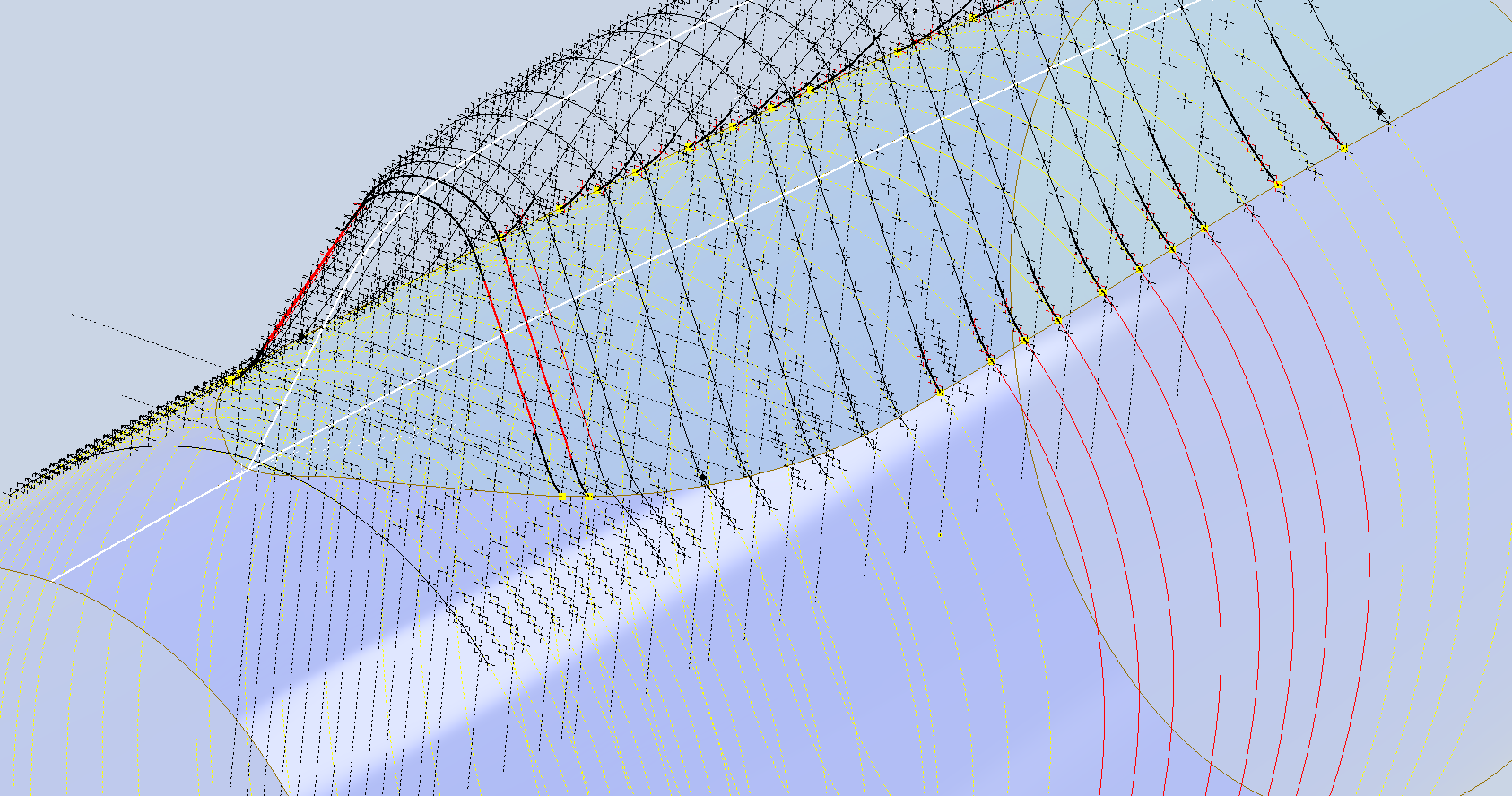
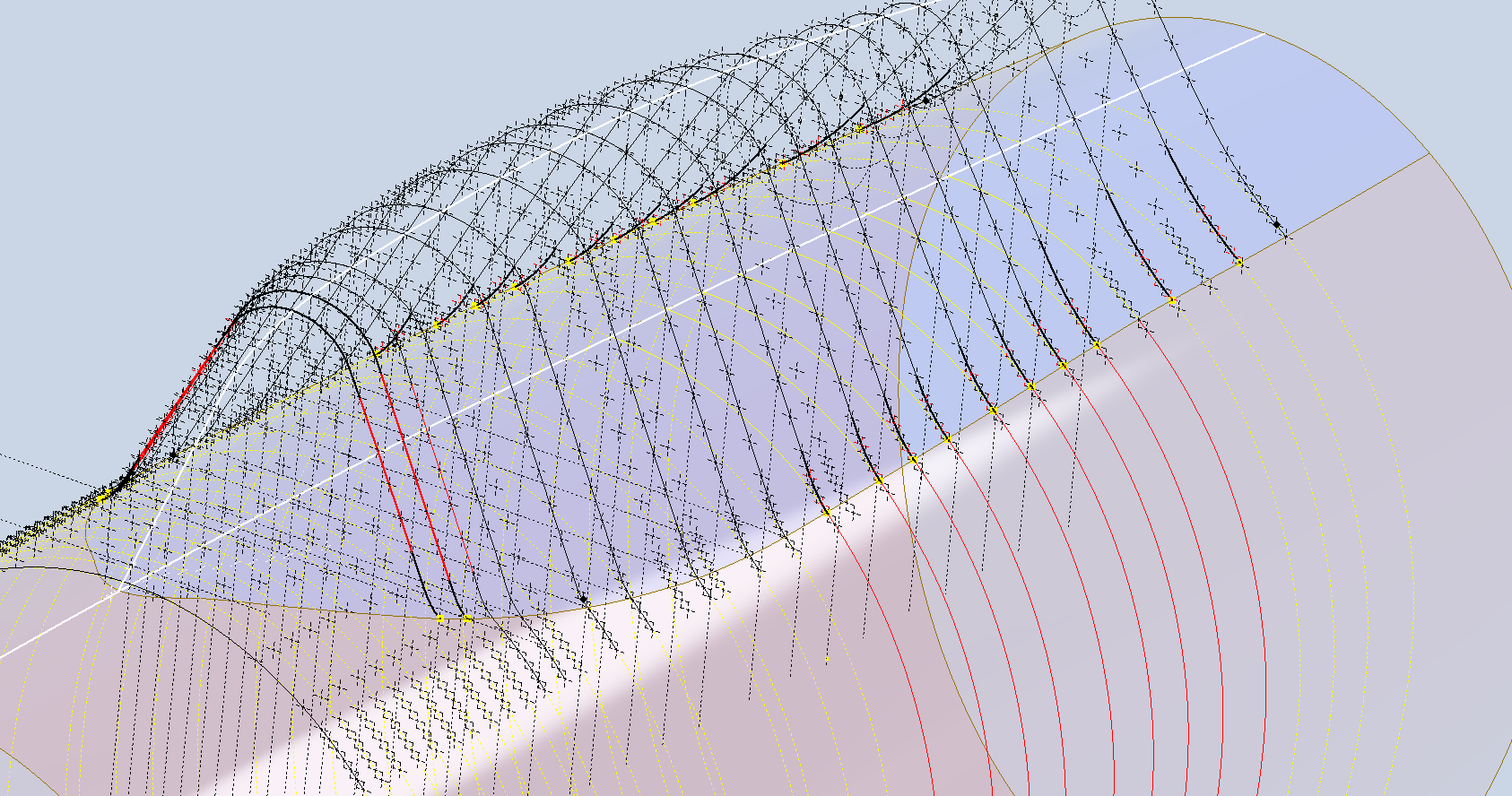
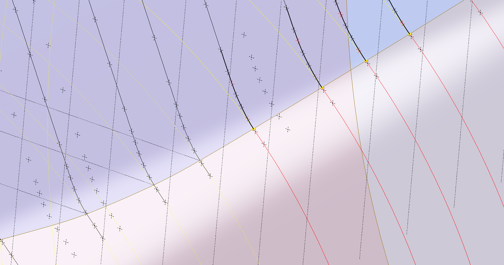
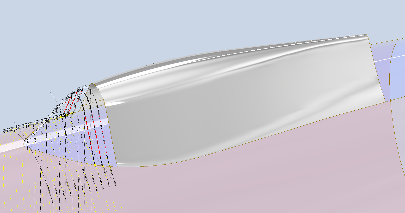
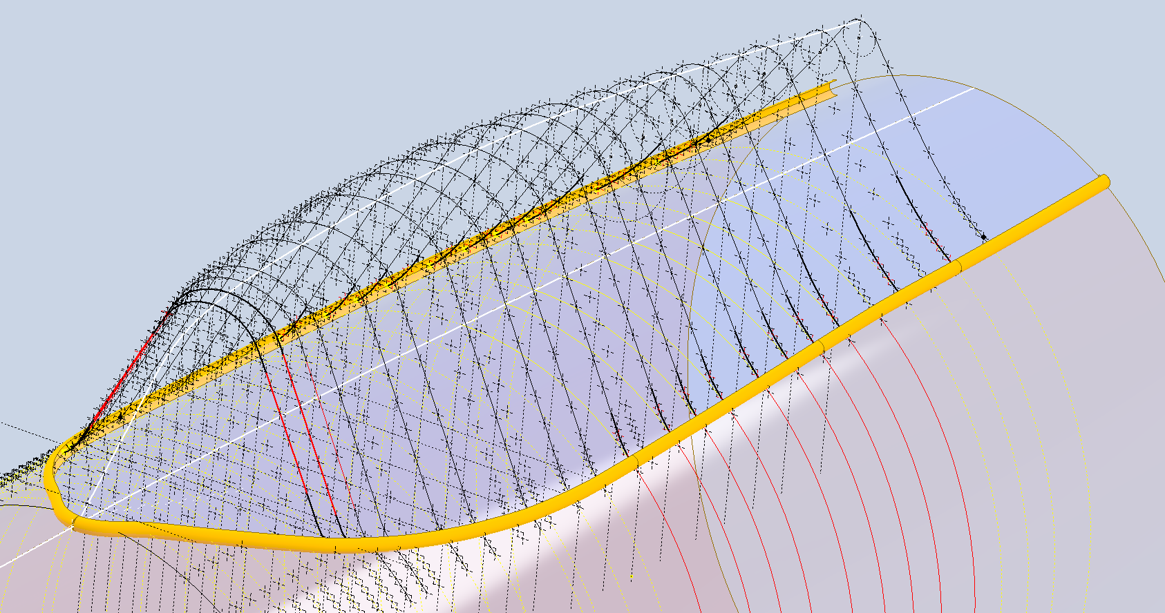
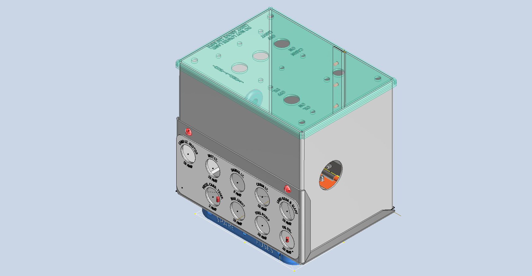
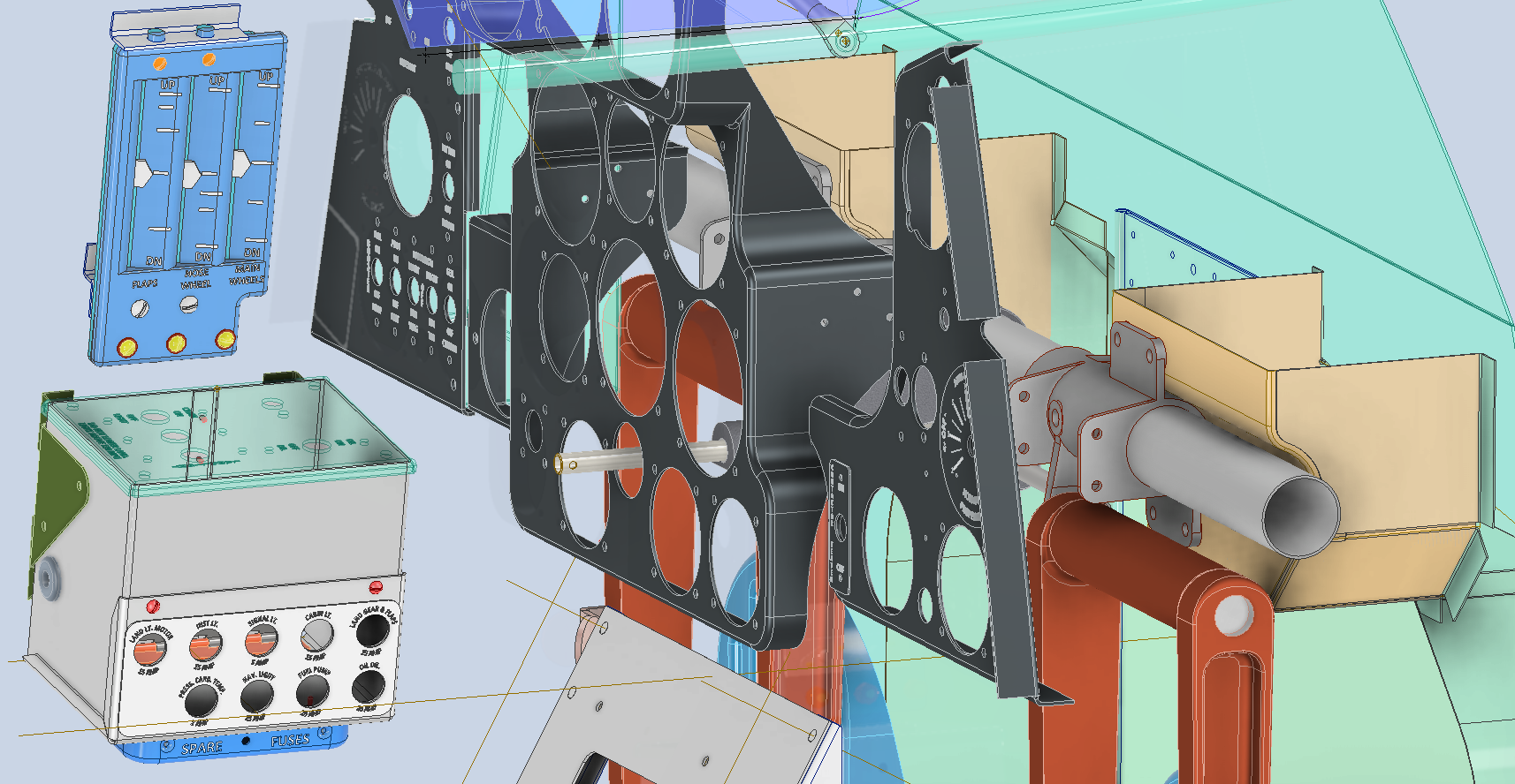
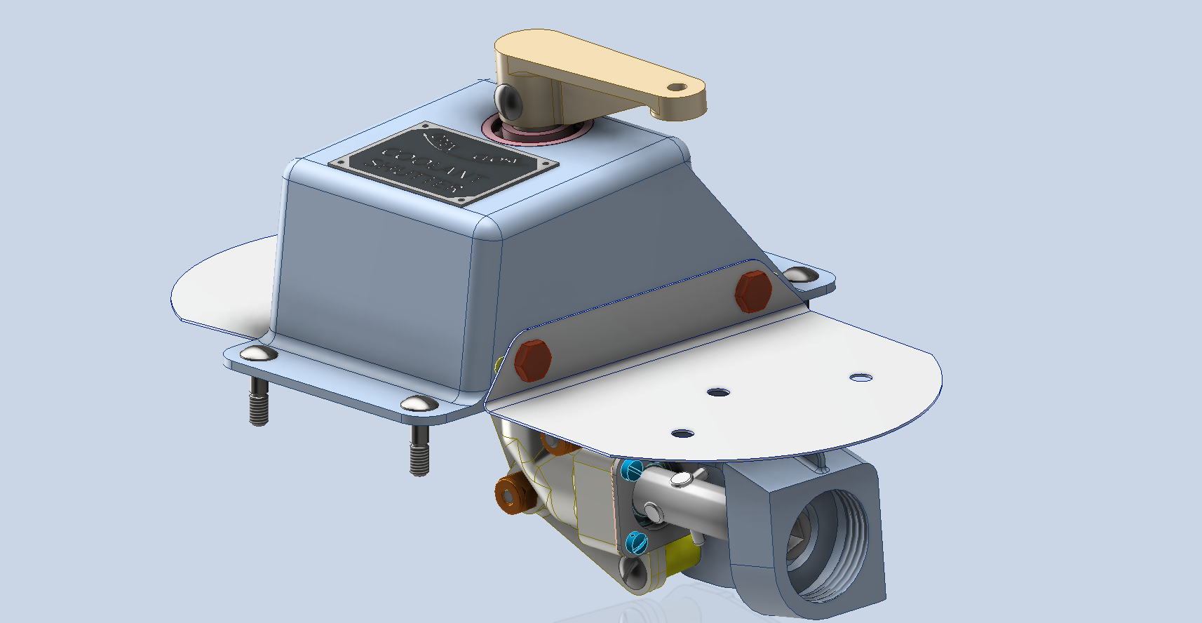
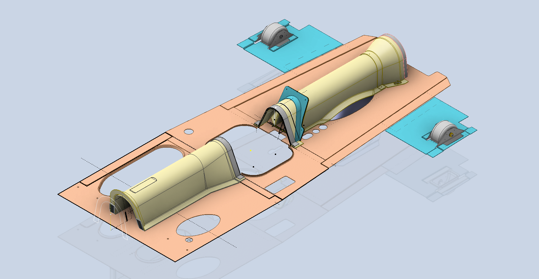
A few screen shots showing the latest updates to the JRF Goose. The wing has been completely rebuilt with all dimensions verified.