Technote: P-38 Forged Parts

Technote: P-38 Forged Parts

I had promised an article on the P-38 Flap CAD development as a follow-up to my earlier article on this topic…but I deviated slightly to address a question from a reader about Forged Parts.

Typically for all these aircraft Forged parts are the main element in the process of manufacturing complex parts that may be used in such applications as Landing Gear. Such is the case with the P-38 Lightning where we have the main support members that are machined forged parts.

I have touched on this briefly in previous posts: Technote P-39 Inventor Face draft and P-51d Mustang Tailwheel Down Position support. Those articles tend to focus on using the Face draft feature in Inventor and using Derived model parts to differentiate between model states i.e. Forged and machined. I should note that with the later versions of Inventor, it is possible to contain the various Model states in one part file but I prefer to use separate derived Part files. The reason is that they are in fact 2 very different manufacturing processes and the drawings for each model may be sent to different departments or indeed different companies. So it makes sense to keep them separate.

In the example above we have 2 components for the Main Landing Gear and the Nose Landing Gear. Both examples use the derived parts process as you can see. In this article, I wanted to cover some of the frustrating differences that you will likely encounter when building these models.

Forged Parts are notoriously complex and the Lockheed drawings tend to only provide the main dimensions and key elements often omitting small details that are likely to have been decided by the mold maker. To determine missing details I often build the models as a surface and then turn that into a final solid.

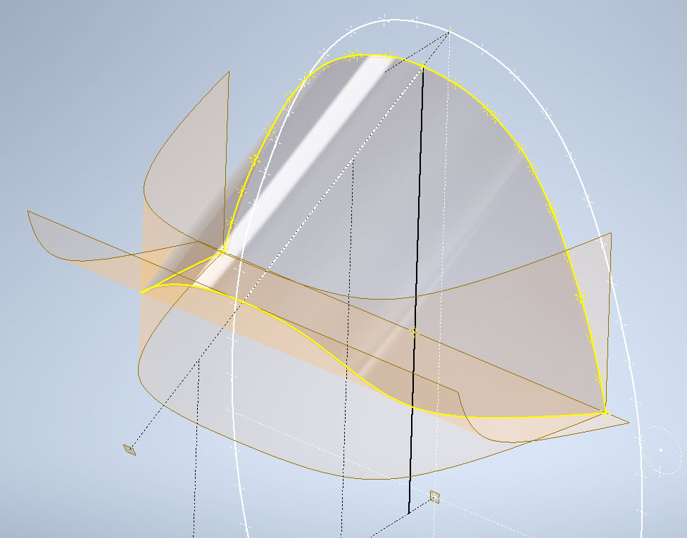
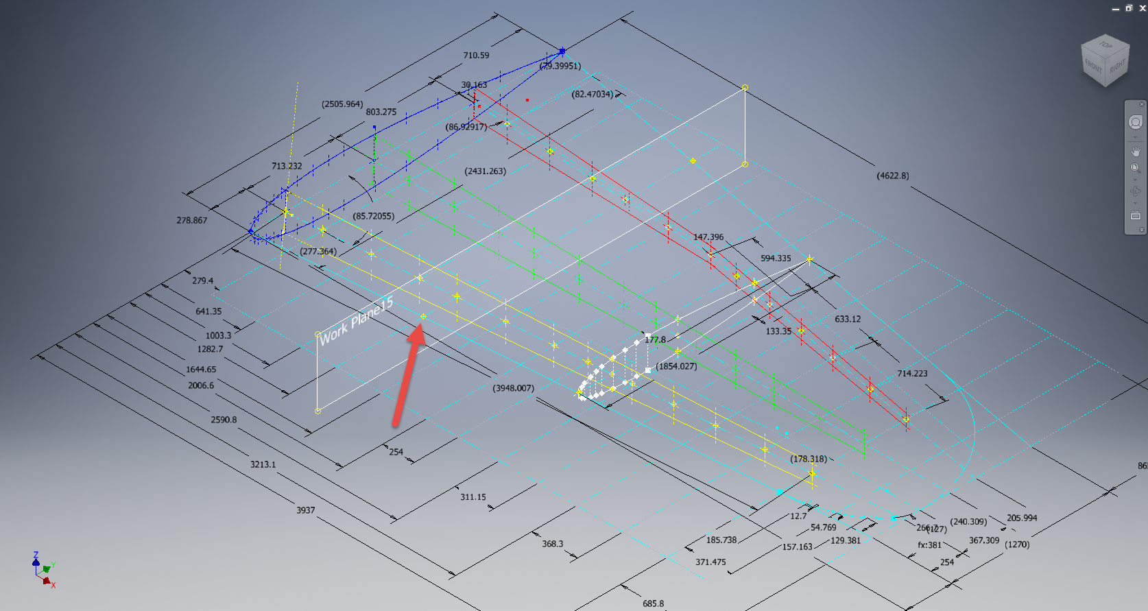
In the above images, this part had an elevated top and bottom section interspersed with a waveform for the main body. The 2d sketches were drawn outside the main part body to make it easier to visualize and manipulate the part data. This part used 3d intersection curves to generate a sweep path for the top and bottom profiles and the surface trim command to profile the main body.

Incidentally, although the sketches do not share the same space as the main model you can still select a single line from any of the sketches in order to trim parts and surfaces in the model…they do not need to be connected. I have often seen folks extrude surfaces from external sketches and then trimmings to that surface but you don’t have to do that…just select the line.

One of the key details that is not clear in this particular example was the protrusion just above the cylinder at the front of the model. All you have on the drawings is a line on elevation and 2 lines on the plan sketches..the specific details of how this small detail interfaces with the main body is down to interpretation. I modeled it with the flat upper surfaces tangent to the curved edge and applied a fillet to the intersecting sides. I did look at a number of variations but I think the end product is close to how it will actually be. This is the frustrating bit when trying to decipher designer intent with limited information.

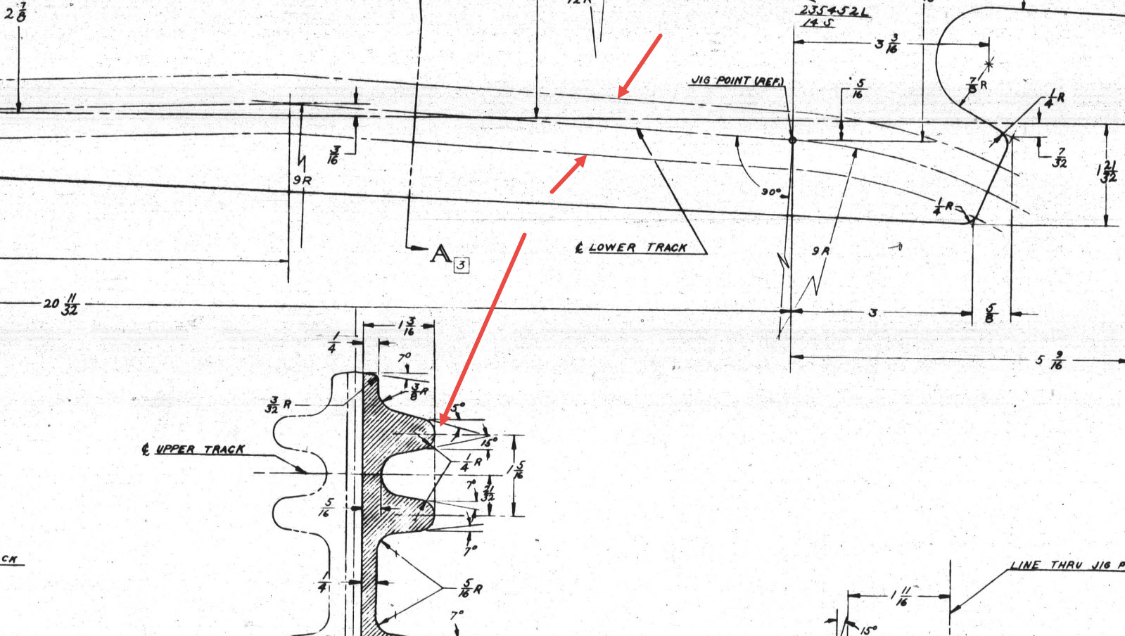
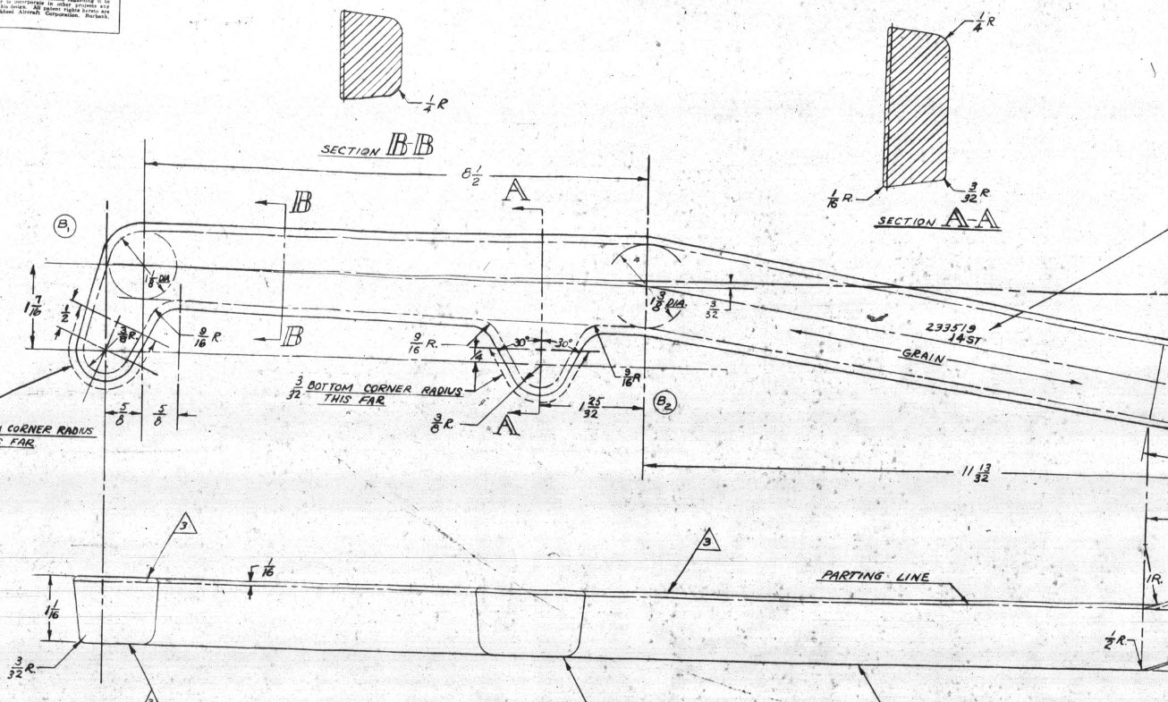
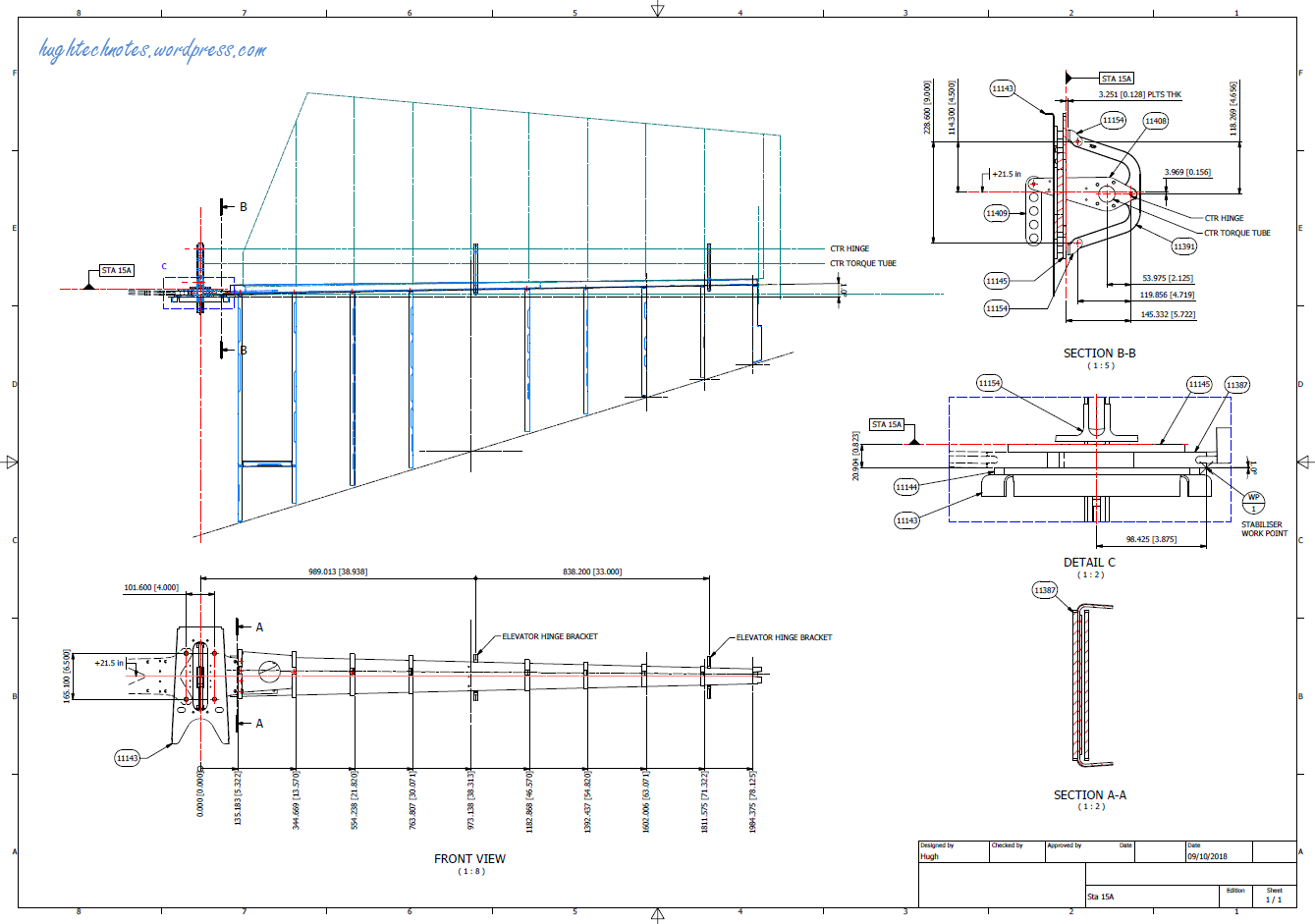
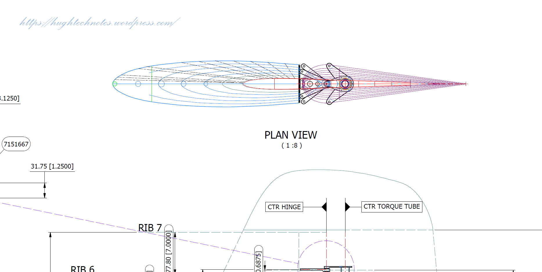
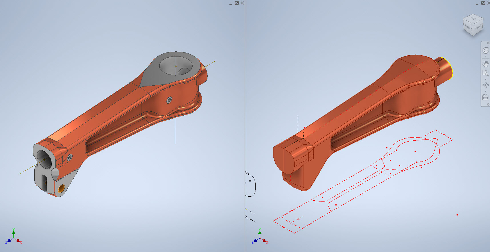
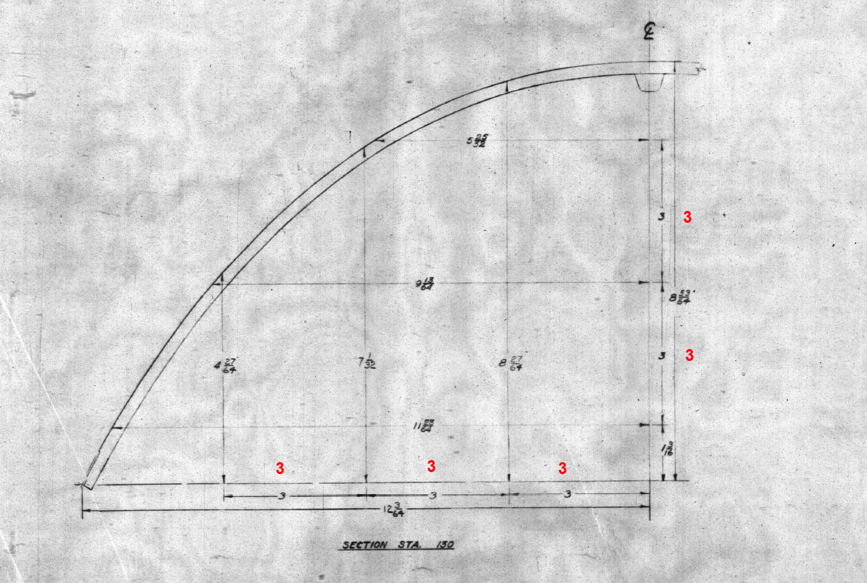
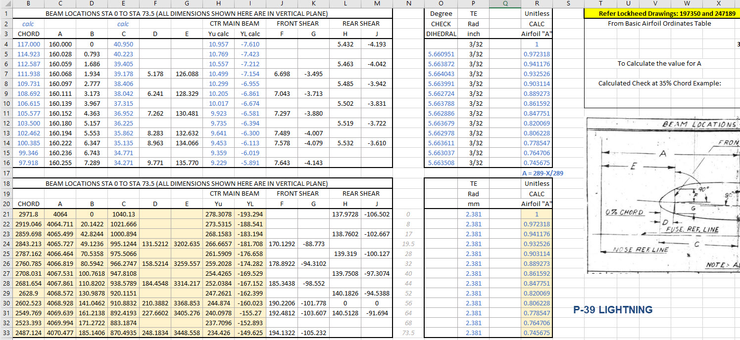
Some of the complexity comes from how the drawings themselves depict the dimensions of the profiled sections. In the first image above we have the criteria shown as the center line of the section’s curved profile. The second image shows a different part however this time the dimensions are to the projected edge intersection of the curved profile. The third image is also similar where the dimensions shown are to the projected intersections. The final image is the Flap carriage arm with the dimensions shown to a dotted line which is not clearly defined on either the sections or the main views to determine what this actually is. After much deliberation, I deiced to interpolate this line as the projected intersection of the drafted sides with the top and bottom faces. I had initially suspected this was to the corner tangent but that would entail a very complex development process due to the varying corner radius.

As you look through the dozens of forged part drawing there are all sorts of variations on the theme with few consistencies. This is where you can spend a lot of time determining how these dimensions relate to the model and how best to incorporate this information in such a manner to keep the model as simple as possible. Consequently, it is not unusual to spend upwards of between 3 and 4 hours modeling the forged parts. I think for the most part where doubt exists to work to a projected intersection as the point of dimension…it will be a lot easier to model and saves a whole lot of frustration.

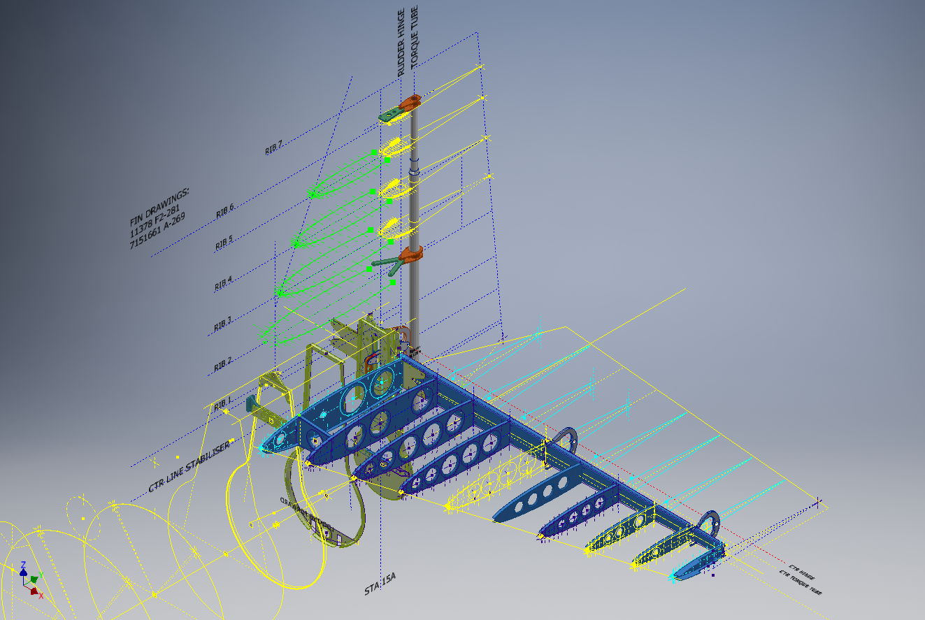
To give you some idea of progress on the Nose Landing Gear models:

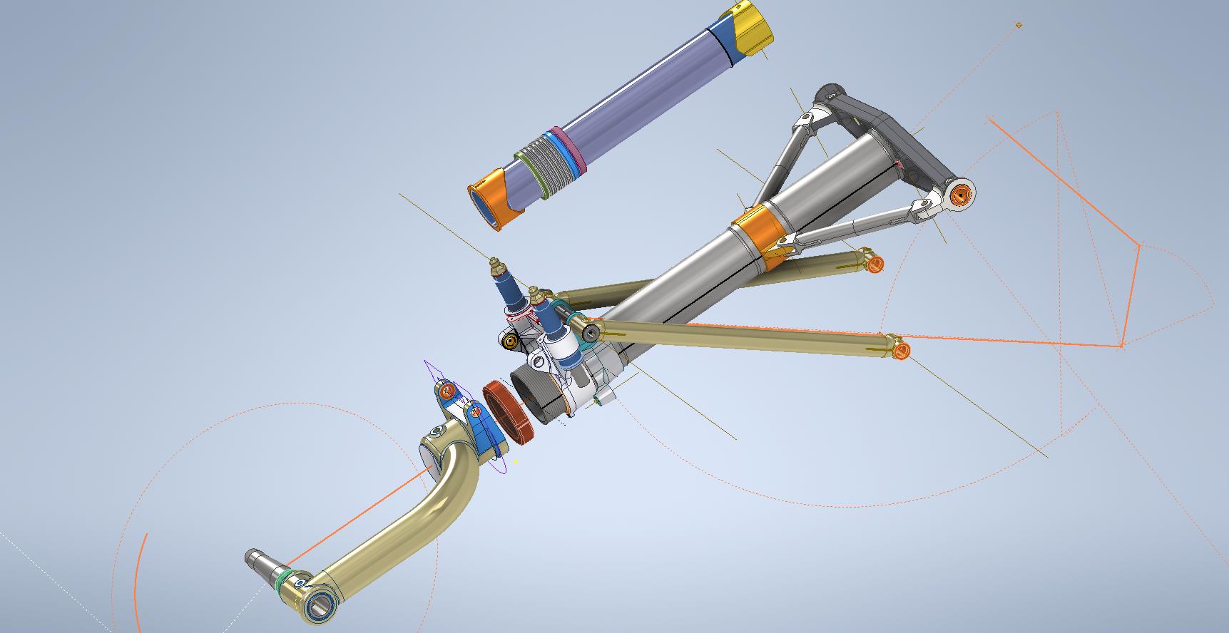
In the latter 2 images, you may notice small differences which relate to the various model variances. I am modeling the P-38H and the comparison photo is the P-38J.

TechTip: Variable Fillets:

When modeling these complex parts often applying fillets can yield unexpected and undesirable results.

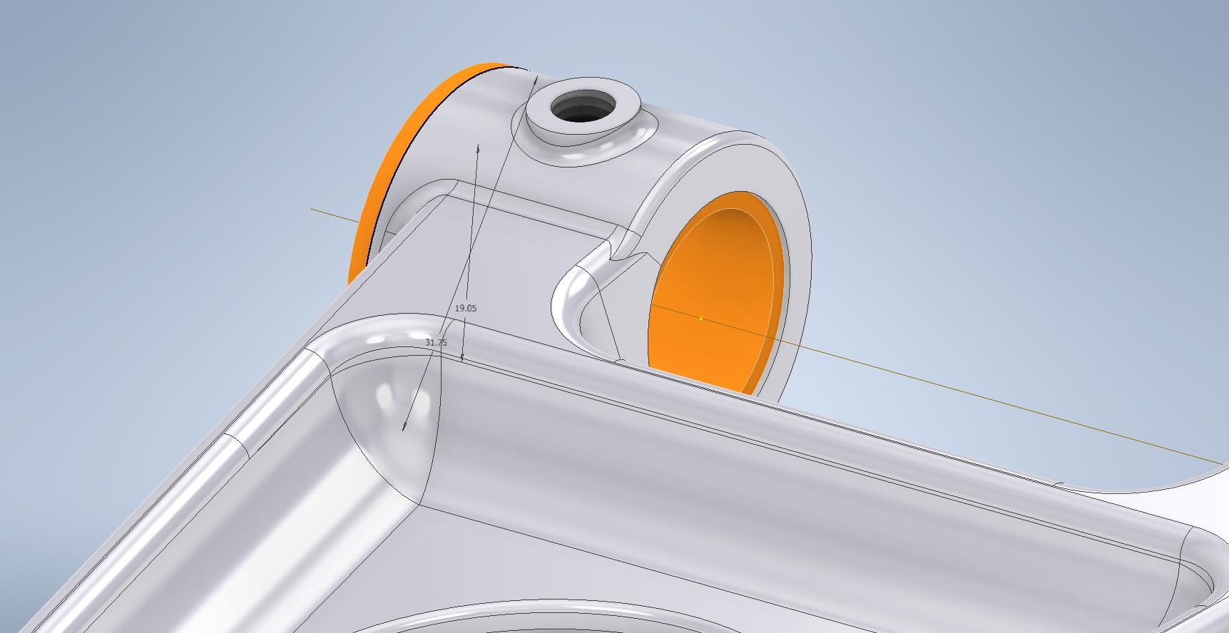
In the images above you can see how applying just standard fillets of different radii can result in quite an undesirable intersection between the flat plane and the circular node. What we need is continuity to achieve a smooth transition from one edge to the next as shown in the second image above. This can be achieved by using the Variable fillet feature.

Variable Fillets give us the option to vary the radius of the applied fillet. When you first apply the Variable Fillet you have a radius specified for the beginning and the end of the selection…you can apply additional points anywhere along the length of the selection to which we can adjust the radius at those points.

You can also add selection sets of edges to the original selection which have their own capacity for separate adjustment. To achieve our goal here for fillet continuity I have 4 selections: the top planar edge (1), the node circumference (2), the lower planar edge (4), and the remaining node circumference (3). It is important for each selection set fillet to have the same radius at each intersection to ensure continuity.

Each selection set is listed separately in the dialogue box and the way to adjust them is to simply select the edge selection as I have highlighted with the first one…this shows the applied points and values in the area below under the heading “Variable Fillet Behaviour”. I have added additional points to the planar fillets at 1 and 4 where the value is set to 2mm which then defines the radius between those 2 points. A small point worth noting is the diagonal draft parting line on the face of the round node that prevents selection continuity which is why we have 4 selections and not just one continuous.

It does not take long to do this and the end result is much more agreeable.

Technote: P-38 Lightning Dive Flaps

Technote: P-38 Lightning Dive Flaps

This is what I am working on now: the P-38 Lightning Dive Flaps. At the moment this is a multi-body part file which I will then extract as separate parts and then assemble. The plan is to also include all the mechanical components to analyze operational criteria.

I shall add to this post as this part of the project progresses and perhaps add some notes on Simulation within Inventor. I should note that the external panels are actually transparent to show the internal lightening holes depicted in these images.

Update Dec 7th 2022:

The mechanical components are now modeled and temporarily located in the Dive Flap assembly. It is actually quite a substantial mechanism that is currently missing the main hydraulic operating cylinder. That component is a contracted supply unit for which I do not have any details so the simulation will use a proxy component for purposes of evaluation.

Before I get around to doing that I must first locate it on the underside of the wing…that will need to be partially modeled with local ribs and struts in order to define the fixing bolt locations.

Update Dec 8th 2022:

Another day, another update. I now have the rib at Station 146 and 158 modeled primarily to assist with positioning. The Lockheed layout drawing for this assembly is not included in the archive so I had a lot of research to do to get this thing in the correct position. What I noticed is an access hatch on the underside of the wing which this assembly effectively replaces so that was useful in this task, though I had a lot of rivet holes to position to get it right!

You will notice that the assembly now has the operating cylinder…I was lucky to find a drawing for this that provides much-needed data for maximum and minimum travel. Actually, I call it an operating cylinder but technically it is a linear actuator gearbox.

When I inserted this item into the assembly it provided a positional check on the main assembly.. which incidentally was perfect.

A few bits to tidy up and then move on to a simulation…I shall upload a short video to Youtube when that is done.

Update 9th Dec 2022:

I have cobbled together a quick video showing the operational aspects of the P-38 Dive Flaps. I am working on a more detailed video which won’t be ready for a few days…so check out this short version for now and let me know what you think.

https://youtu.be/95d8tc3wd14

The technical bit: Each of the 3 flap panels comprises 3 layers of sheet metal with a total thickness of 0.18 inches or 4.572mm. The mechanical assembly is fitted between Ribs at Station 146 and Station 158 and driven by a Linear Actuator. The Dive Flaps were designed to be retrofitted to P-38 Lightning prior to P-38J which explains the location of the main support frame which aligns with the hole centers for a wing access panel and the forward panel fitted forward of the main beam. For reference, I have included a selection of design operational data and some close-ups of the mechanism. that you may find interesting below.

.

.

Technote: P-39 Airacobra Exhaust Stack

Technote: P-39 Airacobra Exhaust Stack:

This rather small unassuming item is at first glance a straightforward little model that actually turned out to be a huge headache. I spent several days working on this model which will all be explained in this article. Hopefully, the solutions I found can help you.

The first hurdle was the Bell Drawing 12-614-001… several key dimensions were illegible and a complete end section was non-existent. The first task was to develop what I do know to help determine what I needed to know…that in itself took an inordinate amount of time but eventually managed to get that sorted. In addition to the sections shown on the drawing I needed to include a control sketch to control the dimensions of the eventual loft activity…this was essentially an ellipse with fixed height and variable half-width.

The side/outside lines of the Exhaust Stack are fixed profiles so it will be the inner profile that will change to make sure that the intersections of the 2 pipe exhausts were correctly located in the centre of the element.

You will notice the side profile sketch is separate from the main model sketches, this just makes it easier to see what I am doing as for the most part, it was mainly for reference.

At this stage, everything is quite straightforward as all I had to was loft the 2 pipes by selecting each of the profiles as shown and then trim the surfaces to give me a base model. A small tip: for this to work correctly and ensure the alignment with the external lines and allow for expansion internally it was necessary to loft using the Centreline option…the centerline holds the loft shape between sections normal to the centerline.

This is where everything got crazy. The main body part of this stack has no joint seam and is quite bulbous…so what I had to do was adapt this base model to form the bulbous surface complete with an internal curve.

As you can see in the image on the right the real item shows the bulbous main body part and the generous inside curve. By the way, some may have observed the real item looks shorter than the model…this is a puzzle…some of these exhaust items are indeed short and this is further noted on the Bell drawing as a dotted line! I suspect this may be linked to the engine used but as yet I do not know for sure.

I initially created the short version thinking that this was normal until I found out that most are actually longer versions. That was the start of many frustrations to come as that first batch of models was quickly scrapped and started again. That bulbous bit though is the main problem.

In order to achieve this I had to derive a solution that filled the void between the 2 tube lofts and at the same time provide an internal curve consistent with the real product. What I opted to do was simply trim and then remove the inner surfaces and then blend the remaining void with a surface patch.

My initial effort was to remove the centre section according to the natural divisions along the centre of each tube and the sketch plane. I tried variation after variation on this, adjusting tangency strength and G2 for each side, I even adjusted the dimensions on the control systems to make minor corrections. I eventually ended up with something reasonable and we got it 3d printed. The second image above is the latest model incarnation which I will explain below.

Two immediate issues are quite visible on these printed models…the initial curve between the 2 tubes is far too tight and almost looks as though it has folded. The second is the surface continuity…okay admittedly I was unsure about the short and long versions of this stack so the end extensions were a separate model part…though I should note that the surface should have been tangential and it’s clearly not.

Coming back to the cad model above…the second image shows what needed to be done. In this one you can see the cutout in the main body is an ellipse which gave much better results and a larger smoother curve between the tubes.

What was happening with effort 1 was that choosing the centre of the tubes at 2 and 3 (which by way was a logical choice) was actually restricting the area in which the inner curve could form, resulting in small deviations in surface accounting for the folded look. Essentially by selecting the centre lines I was actually creating self-imposed restrictions. It took me a while to figure that one out and many hours of work.

Further the mere fact that this patch includes sharp angular corners also did not help as the patch stretches to accommodate those corners again leading to imperfections. Finally, I decided to forego that first attempt and ended up using an ellipse profile that extended beyond the centrelines of the tubes. As there were no sharp edges continuity of the surface patch outline was good and ended with a smoother patch surface that was G2 compliant. There is a small additional patch at the end of the stack…there was a natural seam there which I needed to get rid of.

The final model is shown above and is a very much improved surface with good continuity and a generous internal curvature between the tubes. One final point is the mounting plate… which is not dimensioned on this Bell drawings because it is a contractor-supplied item. I searched through many drawings and found something similar…so I cannibalised the dimensions from that drawing to create the mounting plate. It turns out that this was a good effort as it actually aligns with the engine block.

Surface modelling is rarely this complex but occasionally you will come across something equally challenging. If something is not turning out the way you had hoped or expected just check to see if your choices are imposing restrictions on how the surface is created. When you are trimming or splitting surfaces try to minimise sharp edges and instead opt for curved circular solutions.

Update: 7th October 2022:

Just received word that the newly revised Exhaust Stack model has now been 3d printed…just another 11 sets to go. Apparently, the time for printing and ultrasonic cleaning will be about 4.6 days. They look good…check out the awesome curvature on these prints.

Technote: Steel Coke Plant: Using Regression Analysis

Technote: Steel Coke Plant: Using Regression Analysis:

Slightly off-topic this may be of interest to those working in the Steel Industry, particularly Coke Oven Plant machinery. I worked in this industry for a few years before being made redundant when the company closed operations.

I briefly touched on the Application of surface modelling for tanks and hoppers to ensure volume and mass calculations are correctly interpreted in the CAD model. A link to that article is here. https://hughtechnotes.wordpress.com/2016/12/08/hoppers-surface-model-for-mass-containment/

This company for some reason were unaware of this technique which is one of the reasons why I wrote that blog article as others may also find it useful. An exert from the article:

“This type of hopper is fed from an overhead bunker and releases the fill material through an aperture in the base. The mass volume is modelled according to industry specifications that define the slope of the poured coal defined by the size of the top bunker opening.

The surface represents the containment boundary which has zero volume and zero mass therefore by definition will ensure that the only properties recorded for mass and volume in the 3d model relate only to the fill material.”

The type of machinery used to service Coke Ovens is extraordinarily large and heavy; that runs on rails not too dissimilar to trains. These images show examples of Transfer Cars that essentially transfer coal stored in overhead bunkers to the ovens below.

These machines work in a very corrosive environment and are often replaced with new vehicles after many years of service. A prerequisite to designing is to commission a fully detailed survey of the track rails and surrounding constructions, which provides the basic criteria and envelope parameters to define the design’s physical restrictions.

In this article what I am talking about is related to the rails on which these vehicles will run. As you can imagine after decades of use they tend to shift alignment and are never truly straight and in line. So it is important to have these correctly surveyed in order to determine the ideal location for the wheel centres on the bogeys. Before I started with this company the way this was done was simply to average out the survey information to achieve a suitable centre line on which to locate the wheels. I figured there may be a better way, so I introduced them to Linear Regression Analysis, which essentially does the same thing but more accurately.

Oddly enough the array of points shown in this Linear Regression Analysis is very similar to a survey plot of rails. It, therefore, was a logical progression to utilize this same technique to determine the Best Fit Centre Line for the Coke Oven machinery wheels.

I did this for a number of projects in each case establishing the linear regression for both tracks and in turn defining a line equation from which to extrapolate the ideal centre line. Because the 2 tracks were separate components the line equations would be slightly different with both rails not necessarily being parallel at any given point. So what happens next is to essentially repeat the process this time finding the ideal best fit line between the tracks and then checking in CAD to see how the vehicle would run.

I termed this process as Crabbing, essentially checking the determined centre of the vehicle and therefore the wheel centres along the length of the Liner regression track lines. There is obviously some adaptability built into the bogey designs to account for track variation and it is the purpose of this exercise to determine whether we could achieve movement of the vehicle within the requisite design parameters.

This is also a technique that can be used to optimise ordinate profiles where accuracy is critical. When you think about it most dimensional data points are specified to an accuracy of 1/32″ or 0.7mm which is normally within acceptable parameters however for greater accuracy why not try using linear regression analysis?

It was a useful technique and worked very well. So next time you need to determine the best fit line within a range of static survey points perhaps consider using Linear Regression to help achieve the desired results.

Technote: P-39 Airacobra Update Horiz Stab.

Technote: P-39 Airacobra Update Horiz Stab.

In a previous post, I covered the significant new model for P-39 Airacobra. This model is fully inclusive of all aspects of the aircraft. Within this post, I mentioned the extensive study involved in determining the layout for the Horizontal Stabiliser; the dimensions of which were unclear in the available blueprints

https://hughtechnotes.wordpress.com/2022/05/18/technote-bell-p-39-airacobra-updated-model/

I was particularly keen to establish verification for the leading edge angle and though I had written to a number of organisations that have the P-39; surprisingly none of them took the time to either acknowledge or indeed reply…which of course was disappointing. From my experience, the industry is normally very supportive with regard to technical inquiries.

I revisited the documentation I do have and established that relevant information was included in the NACA Wartime Report L-602 which gives the chord length at Sta 49.25. It turns out; from my initial assessment; that the dimension at “2” was barely 2mm out and the Leading Edge angle is now 16.7796 degrees.

I mentioned in my last post that this latest study is available now which also includes the original model; which was more of a 3D modelling exercise than a dimensional study.

The P-39 Airacobra new CAD/Ordinate study is an impressive project.

All inquiries as usual to; hughtechnotes@gmail.com

Technote: P-38 Lightning Cockpit Canopy

Technote: P-38 Lightning Cockpit Canopy

These are the basic profiles for the P-38 Cockpit Canopy glass panels derived from the XP-38 drawings. Knowing that there were differences between the prototype XP-38 and the production models I was initially reluctant to accept the XP-38 dimensions for developing the cockpit canopy. The production drawings do not contain any useful information to develop these profiles nor indeed was there any drawing stating the inclination angle of the windshield. There was also not enough information from the Lockheed ordinate drawings for the fuselage frames which left me with the only option to use the XP-38 information.

It transpires the dimensions on the XP-38 drawings are indeed pertinent to the production models. There are exceptions which relate to the side windows.

The drawing on the left is the P-38H side glass frame and you can see this is dimensioned as a radius value which differs from the XP-38, which is defined by ordinate dimensions. There is also a slight variation in the overall length, so I naturally presumed that there may be other variables that conflicted with the prototype model. The only way to know for sure was to build the model based on the XP-38 and cross-check against known information with the production models.

So after 3 days of frustrating intensive work, I now have the base model for the XP-38 glass profiles and I have concluded that the profiles for the front, top and rear panels dimensionally are compatible with production variants. The only area that has marginally changed is the side panels, although changing from ordinate to radial dimensions still retains alignment with the known fuselage frames.

Also worth noting is that Lockheed uses a 3-inch grid system for aligning all the fuselage components which are useful when you are trying to locate these panels where no location is noted…you just have to align the 3-inch offsets to the grid. Each of the 3-inch offsets on this drawing section for example can be matched with the full-size grid to locate the correct elevation for the top glass panel and so on.

It is actually a really clever idea and helps obviate any doubt about where an item should be located.

One further tip when working with these Lockheed drawings is that for plan views and elevation views there may not be enough dimensions to fully locate a 3d point for determining a complex curved line.

For the windshield, there was sufficient information in the vertical plane and the horizontal plane but as they were not related I could not derive specific 3d points from this data alone.

So I resolved to replicate this on 2 sketches and extrude a surface profile for each sketch. The intersection of the surfaces gave me the requisite 3d glass mold line.

The final check; that ensures this is correct; is to view the final glass panel along its axis to check that the curvature matches exactly with the top of the ordinate fuselage profile at STA 126…which it does.

For some reason, the ordinate dimensions are on STA 123 instead of STA 126 which means the end result will need to be projected to get the full glass panel model…I haven’t done that here. These are primarily dimensional studies and I tend to only include 3d models where this benefits the purpose of confirming data integrity. Oh by the way the inclination angle for the windshield is 27 degrees…don’t be sidetracked by the frame connectors that show 26.5 degrees…the reason for the 0.5-degree variance relates to the interface with the rubber sealing. Hopefully, you will find this useful.

Technote: Understanding Ordinate Datasets

Technote: Understanding Ordinate Datasets

I wrote an article on using the Ordinate datasets many moons ago, which is now rather dated so I figured it was time to write an update with a better explanation.

First of all the reason why? It’s like every other construction project where you first start with a skeletal framework and then develop the project’s envelope. Whether it be a building with a steel frame, a boat, even the human body relies on having in place the skeleton on which to build the construction elements.

Aircraft projects are no different and to this end, many manufacturers provide this information in the form of ordinate dimensions. This information occasionally is listed in tables or included on the individual part blueprint drawings. I firmly believe that once you have the basic framework dimensionally accurate then everything else falls into place…so it is incredibly important.

Basic Ordinate Overview:

Let’s take an example from the Bell P-39 Airacobra.

For this aircraft, the ordinate dimensions are noted on the actual part blueprints so I have developed a series of tables listing this information in excel spreadsheets as shown. They list the Station Location from the aircraft Zero plane (this is usually identified by the manufacturer). The Station number is actually the station dimensions from this plane which defines the Z component. The next column on the table is the Vertical Y-component or the dimension to the Waterline and finally, we have the Horizontal X-Dim which lists either the Buttock Line position or Half Breadth dimension.

Commonly the Horizontal axis on the aircraft is known as the Fuselage Reference Line (FRL) or occasionally the Thrust Line. The Vertical Line is simply known as the Centre of the Ship to the Aircraft.

Waterline (WL): Horizontal Axis, Buttock Line (BL): Vertical Axis. An example of this is where we commonly have a designation like WL4…which means the Waterline at 4″ above or below the Centre of the Fuselage. So when it is not specifically dimensioned you would know from the designation where it is located.

Once I have the tables of known dimensions I would occasionally extrapolate this data to list the actual X,Y,Z dimensions in separate tables to make it easier to copy and paste into any CAD system.

As you can see from the above image, the dimensions are initially listed in 3 columns, X,Y,Z and next to that is the same data listed with comma delimiters. The reason for this is because Mechanical design packages like Inventor and Solidworks will recognise separate columns of data in the requisite order as stated whereas Autocad will require combined data for Mulitple Point input as comma-delimited.

The way I do this is to have a separate excel spreadsheet which I keep on my desktop which I call Scrap.xlsx. The format is common as shown in the image on the left though I should note the top 2 rows are optional. If there are no units specified it will default to the CAD template units. I usually don’t bother with the top 2 lines. Once the points are imported into CAD I tend to delete the values in the spreadsheet Scrap.Xlsx and start again.

The comma-delimited column data in the above image can also be copied onto a Notepad Text file and used in Autocad. Worth noting is that if you try to import X, Y, Z coordinates onto a 2D sketch it will only import the first 2 lines and ignore the third…so make sure the columns are in X, Y, and Z-order.

An important consideration is that not everyone uses Inventor or Solidworks or even Autocad which is why the spreadsheets are critical because then everyone can use the data to build their own models.

Actually building the model can be done in several ways. You can build a part file with multiple workplanes on which to sketch the profiles from the input ordinate data or individually in separate part files. You can model the parts in context, i.e. taking into consideration the Station (Z-axis) dimensions so when input into the assembly they locate correctly in 3d space. Or just the X, Y, ordinates in the part file and locate to the Z-axis offset in the assembly.

Dealing with problem data:

This is perhaps one of the main driving initiatives behind the development of Ordinate datasets with regards to the legibility of the original manufacturer’s blueprints.

This example is actually quite reasonable whilst others are quite illegible. As most of these datasets are listed in Inches; which are normally factions; it is easy to confuse whether a fraction is 3/16, 5/16 or 9/16 when all you have is a blob of dark matter.

What I tend to do in these circumstances is develop what I do know and develop the profile using splines to connect the points and then apply the curvature to help determine the missing point location or check that a point is correct.

Occasionally points you need to complete a profile just don’t exist on the blueprints or are completely illegible which will then require more extensive research. Sometimes this information is included in the maintenance or Repair manuals or in the case of the P-51 Mustang a missing point was actually found in correspondence. Either way compiling this data and building the profiles is very time-consuming.

Another fairly common problem is wrong dimensions. Every aircraft project I have worked on from this era has this problem, not because they are bad draughtsman (very much to the contrary) it is because many of the drawings are only records of the Template Lofts and occasionally the dimension is recorded incorrectly. The skill is identifying that the dimension is wrong; it is unwise to assume that because something does not look quite right that it is actually a mistake. So you have to check with associated parts and layouts to be sure.

The image above is the Horizontal Stabiliser leading edge. The rib in blue (1) was obviously wrong because of a distinct kink in the curved edge, which when corrected aligns well with its neighbours. The one in red (2) also appears to be wrong even though the curvature looks fine the forward edge does not match with the projected alignment (I tend to use an Axis feature to check this). Before I apply any corrections I will check the part drawing and then the assemblies to determine if there is an error or if it is actually a design feature.

Locating Sketch Datum Points:

Creating workplanes for sketches as offsets from the primary X, Y or Z planes tends to copy the originating plane datum point which is not always where we need it to be when importing a series of points. The best option is to use the Parallel To Plane Through Point when creating a workplane as this allows you to select the point which will be the datum point on that sketch plane for locating the point data.

I previously wrote an article on this here: https://hughtechnotes.wordpress.com/2017/07/27/technote-inventor-sketch-datum/

Some of the datasets are setout specifically to make it easier to input the data from the spreadsheet. For example, the extrapolated X, Y, and Z, coordinates for the P-51 Mustang wing have been compiled and calculated so they will input at the location of the 25% wing chord. This is assumed to be the logical setout point from the CAD World Coordinate system which saves you a lot of hassle.

If however, you have to create a workplane on an incline this option may not be available in which case you need to adapt the local sketch coordinate system to suit the required datum point.

In Inventor, you would right-click the Sketch in the model browser and select the Edit Coordinate System option which initiates an adjustable Coordinate icon on the sketch.

Suffice to say this icon can be manipulated, moved and rotated to any point on the sketch to suit your requirements. I will do a more comprehensive article on this shortly.

Other Excel Ordinate Examples:

The actual layout of the Ordinate spreadsheets depends entirely on the form from which the data is developed. Where the original blueprint data are listed in tables I will generate the excel spreadsheet in exactly the same format…which helps when checking the data input. If there are no tables but data from the part drawings then I will generate tables according to how the dimensions are noted.

All the dimensions are listed in Inches and Millimetres. I normally extrapolate the X, Y, and Z coordinates to millimetres as this is easier for me to work with…but it is easy to change that to inches if required. All the spreadsheets are fully editable and not restricted in any way.

Finally a quick Excel tip:

If you work with percentages a lot you will find this useful. When entering the value in the cell just add the % sign after the numbers and Excel will automatically format the cell as a percentage value.

Ordinate Data set Availability.

The NAA P-51 Mustang (probably the most comprehensive study) is available as a separate package from the Blueprints archive. The B-25 Mitchell is also a separate package and the Grumman Goose. The F6F and F4F are currently included in the Blueprint archive as they are not so well organised (work in progress) for now.

The Bell P-39 Airacobra is currently included with the blueprints but as I am now working on a new update this will shortly only be available as a separate package.

The P-38 Lightning is brand new and will not be available until June.

Final Note: All the Ordinate packages include the 3D cad model as developed in Inventor. This should not be an obstacle to anyone wanting to interrogate the model as a 30-day evaluation of the Autodesk Inventor is readily available for download. You can even extract sketches from the model as DWG files if required.

Many of the Ordinate packages include fully dimensioned Autocad 2D drawings and PDFs. These are mainly layout drawings and critical location information where it is essential to better understand relationships between wings, fuselage and empennage. Again all these are fully editable.

For all inquiries and feedback please get in touch: hughtechnotes@gmail.com

Technote: Autodesk Inventor 2022 Part Model States

Technote: Autodesk Inventor 2022 Part Model States

In a previous Technote I briefly introduced the work method for Derived parts that provide the capability of managing model states i.e. from Forged part to machining; as separate part files. This was included in a discussion on the P-51 Mustang Tail Wheel down position modeling.

Inventor 2022; just released; now has a feature called Part Model states which will enable you to manage manufacturing operations, dimensional variations and simplified representations all on one part file.

Check out the introductory video on The Autodesk website for more details on this feature as well as more information on the latest release of Autodesk® Inventor®. This is packed with user-requested updates and enhancements to help manage your design process, speed up your connected engineering workflows and reduce repetitive tasks.

Whilst Autodesk Inventor is not normally associated with the Aviation industry it has a very advanced 3D toolset that adapts well to this industry as I have demonstrated in the many Technotes throughout this blog. So do checkout my previous articles on using Inventor in this environment and drop me a line or comment below. More information on Inventor 2022 and specific tutorials on utilizing the host of features within Inventor will follow.

P-51D Mustang – Instrumentation Panel

P-51D Mustang – Instrumentation Panel

I have recently been working on updates to the Ordinate and Cad package (as noted in the previous posting) and also developing the Instrumentation panel assemblies for the P-51D Mustang.

What started out as a mere curiosity is actually turning out to be a fairly intensive project requiring a lot of research.

For the P-51D there are at least 4 variations on the main instrumentation panel for the early and late models. The U-shaped Support frame has 4 variations and just as many for the lower instruments panel set at 20 degrees to the main panel. It is important to get the correct combination of components for the various model numbers which is where a lot of my time is spent on the research.

Part of that research is, of course, getting the label text just right which is where I encountered a lot of frustration. The generic text font used on the Mustang and many of the contemporary aircraft at that time was the MS-33558. There is a TTF font available online for download but the design is not very good with problems of self-intersecting edges and spacing definition.

Military-Standard-MS33558ASG
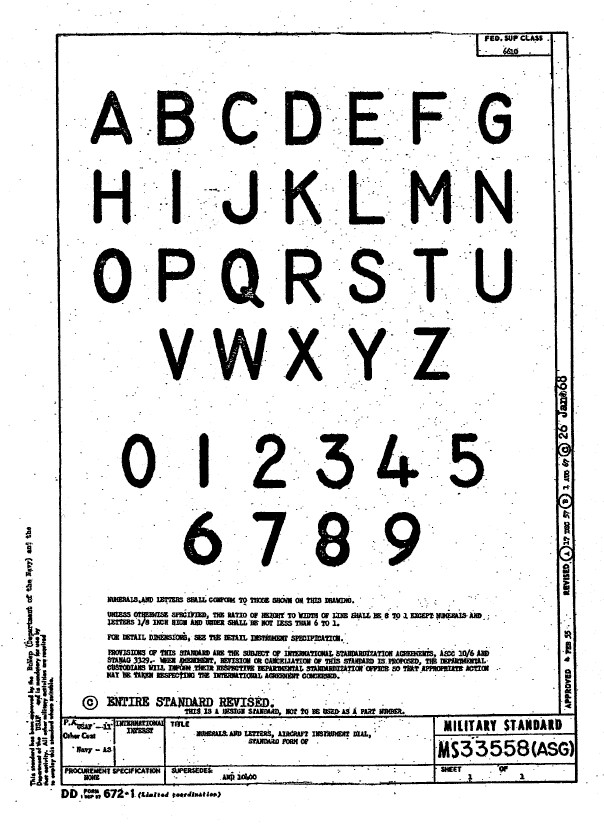
Using this font in CAD systems will result in problems with embossing or extruding.

Typically I had to find out why, so I downloaded a copy of Fontforge to analyze the characters and identify the problems. Most of the characters are fine but there are at least 7 that have intersecting line problems. However, due to the nature of the font construction process, it is very difficult to identify the problem areas and thereby to devise a solution.

I spent a few hours looking into this but font development is a relatively new procedure for me and I did not achieve any satisfactory results. This I think needs an expert touch. I appreciate the work that was done in developing this TTF but please whoever designed it just a bit more attention to detail would have saved me a lot of work.

In the interim, I decided to use the closest font I could find on my system which was a default SolidEdge font that is similar in style. I had SolidEdge as a trial program a while back and thankfully it left the fonts behind when I uninstalled it.

Another small point worth noting is the color of the label text. The images above show the early P-51D version arrangement and you will notice in the bottom left corner of the first image is a selection of text in red. It is “EMERGENCY” with an associated note. The drawing states that this is RED on a black background but many of the photos I have seen of this particular version show the text in white. So the question is did NAA change this at some stage or is it just down to restorers’ preference?

Grumman F4F Wildcat: Aileron:

Grumman F4F Wildcat: Aileron:

Having made good progress on the ordinate set for the Grumman F4F/FM2 I decided to put the spreadsheets to one side and do some modeling to verify the dataset. Normally this would not be required to such an extent but I needed to do this to check the relationship between the components and aircraft datums.

I was spoiled with the P-39 project where virtually every component has reference dimensions to the ship center line or thrust lines so positioning was a breeze. However, the F4F drawings sadly lack this reference information on many of the key drawings so developing the 3d cad model is the only sure way to ascertain this data.

F4F Aileron Render

The above model is the left-hand Aileron modeled in Inventor and rendered in Keyshot. Keyshot is a very good renderer, even for a novice like myself; in which you can generate acceptable renderings very quickly. The real-time rendering is very good and will continue without glitches even on a modestly specced system (unlike some of the alternative products). The user interface is logically set out with a good library of materials and textures. I would highly recommend this product.

Getting back on subject; the Aileron ordinates took a long time to complete for various reasons; requiring constant checking and verifying. Once this was done, the modeling was reasonably straightforward except for the small trimming tab. The drawing dimensions are slightly out, so I extracted the neighboring rib profiles to create the template for a finished model.

I also decided to create a few scrap drawing views as a matter of record that will be useful when I eventually move onto modeling the wings themselves.

F4F Aileron 4

For reference; the following image shows the Ailerons attached to the wing assembly. Hinge positions checked and verified with hinge brackets (orange) fitted achieving a planar variation of less than 0.04mm.

2018-10-07_22-29-40

There are still a few items required to complete this model but this is not a priority for me right now. My next objective is to develop the ordinates and perhaps some modeling for the vertical and horizontal stabilizers.

Horizontal Stabiliser & Elevator:

Grumman F4F-FM2 Horiz Stabiliser

F4F Stabiliser

f4f rear fuselage

Tail Fin & Rudder:

F4F FIN RUDDER

F4F FIN RUDDER 01

Fuselage Frame 3:

F4F Wildcat Frame 3a

If you are interested in obtaining my research data for this aircraft then please send me an email. At the moment this is an unfinished project but the available drawings (12) are fully dimensioned which will help you with establishing correct datums and station frame associations along with a few spreadsheets. HughTechnotes@gmail.com