HiRise data and WRL Conversion.

HiRise data and WRL Conversion:

It has been a while since I last posted an article due to being busy with other projects. During some research activites, I came across a number of subjects that may be of interest, two of which I would like to share.

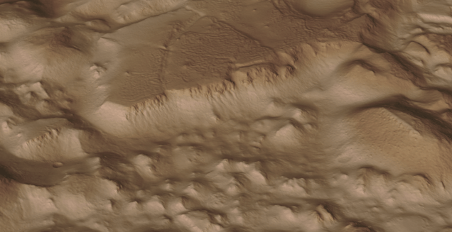
The first one is the HiRISE Digital Terrain data models on the University of Arizona website. The website contains datasets that are digital extractions of surface terrain scans of the planet Mars. The DTM datasets are publicly available for research and modeling of geological processes.

PSP_007100_1520

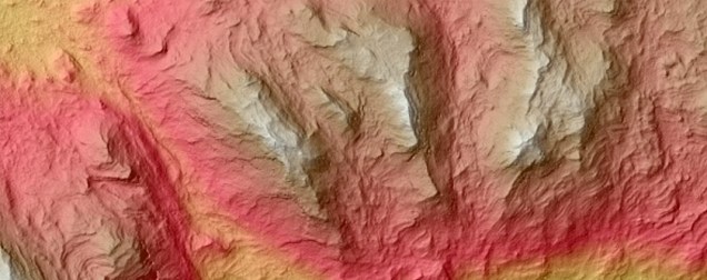
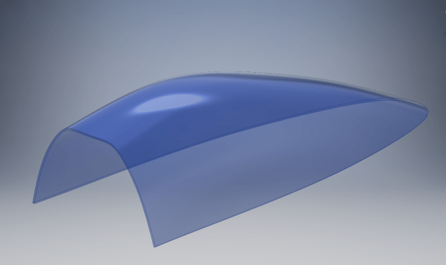
Naturally curious I decided to investigate the possibilities of modeling and rendering of these datasets from which I produced a few preliminary 3d terrain models using Blender and rendered in Keyshot…Gorgonum Chaos:

mars10The technique I used is described in this video on Youtube, clearly explaining the process. To me, this is incredible stuff and thanks to the University of Arizona for all their dedicated work in developing these datasets. So have a look and check it out for yourselves.

The next subject is WRL. WRL is a file extension for a Virtual Reality Modeling Language (VRML) file format often used by browser plug-ins to display virtual reality environments. VRML files are known as “worlds,” which is what WRL stands for.

One of my many interests is Tensegrity, a structural form of tension and compression members first developed by a chap called Kenneth Snelson. The internet is full of examples of this structure concept inspiring many variations from fairly simple to very complex designs. I have developed a few of my own.

delta

Many of the practitioners in this field make datasets available for personal use and one particular format they use is the VRML (WRL) so you can view the design in 3d.

For the simple structures similar to this image the design and construction are not that difficult, however when it comes to developing your own version of the more complex examples it can be a real headache. Although some datasets include actual point cloud data the process of matching pairs of points to reconstruct the design can be a nightmare.

The obvious solution would be to convert the WRL model into something usable that could be used as a guide for developing a 3d cad model. I tend to favor Meshlab for doing this as it is one of the few programs that will accurately convert the imported data.

meshlab

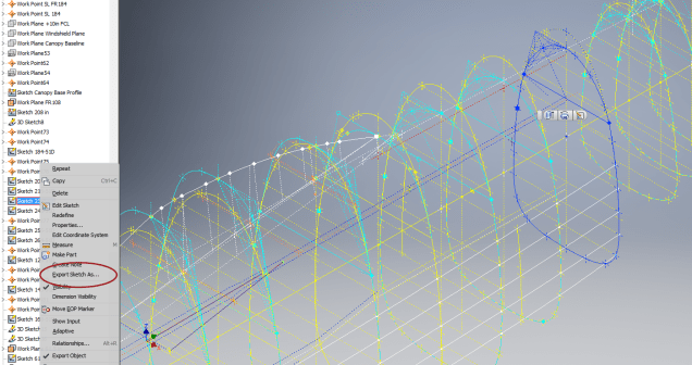
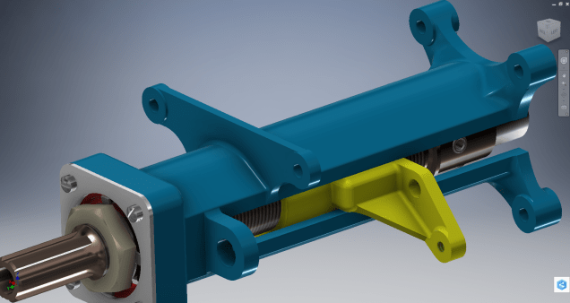
The WRL model is converted into a series of mesh objects that we can export as an OBJ or STL file and then import into Inventor.

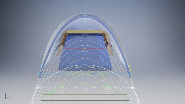
Once in Inventor, it is simply a case of selecting each of the compression struts and “Fit Mesh Face”. Select the “Auto Fit” option for each member and it will create a surface from each mesh representing the struts.

The tension wires are then created as a 3d sketch using the background mesh model as a guide. At this stage, the model is a workable composite but may require micro adjustment for the tension wires to ensure the finished item is properly constrained. I would reverse engineer this model and reconstruct as an assembly and apply the microdimensional adjustment to the groups of tension wires to ensure the absolute accuracy of the final design.

It is beyond the scope of this article to go into the detail of every step, but if you require information on any of the topics please feel free to drop me a line.

Tensegrity Conv

I hope you find this article interesting and have fun.

Technote: Inventor Export Sketches

Technote: Export Sketches

The Inventor product has an option to export part Sketches to either an Autocad DWG or DXF format directly from the model environment. This is very useful if you are needing to share development information with someone else who is working with a different CAD product.

It is simply a case of highlighting the sketch as shown in the example below and selecting the “Export Sketch as…” option.

Inventor export sketch

A dialogue box pops up asking for the file format DWG or DXF and location for saving. I would recommend the DWG for the format as this replicates the Splines more accurately.


In this example the left image is for the Mustang P-51 rear fuselage, showing the outer profile for the P-51 B/C and the inner profile is for the P-51D. The image on the right is the fuselage tail-end.

I plan on extracting all the fuselage curves that include P-51D data to DWG format as a reference until such time as I can add the point data to the already comprehensive set of ordinates available here.

Mustang P-51 B/C Ordinates


NAA P-51D: Canopy

NAA P-51D Mustang: Canopy

With the return to the P-51D project, I have been working on developing the fuselage and the canopy ordinates specific to the P-51D. Supporting information in this regard is hard to come by and we don’t have the luxury of tabulated ordinate values and fully detailed mold lines as we had with the P-51 B/C.

What we do have though is critical dimensions scattered amongst the 100s of drawings and documents that collectively help establish key datum points which in conjunction with conic geometric development appear to make this aspiration a feasible prospect. To give you some idea of progress this is a front view of the preliminary P-51D canopy model.

P-51D Canopy Front

I still have the windshield model to develop in order to finalise the canopy design but I am pleased with achieving this amount of progress derived from many hours of research and some straightforward geometric developments. Notice in particular the accurate tangency alignment with the known frame mold lines, it is perfectly aligned. I appreciate that there are a few variations on the profile of the canopies that were made for the P-51; some more bulbous than others, but we first need to establish a baseline which is what we will have.

As a consequence of this activity, I have also managed to develop the rear fuselage profile ordinates for the P-51D. I am rather excited by this new development in conjunction with the completed wing ordinates and the more recent vertical stabiliser it may actually be possible to have a full ordinate set uniquely for the P-51D.

Update: Below is the finished baseline canopy model profile.

2017-06-08_13-55-28

…and this is what it looks like to develop the canopy and windshield with limited known data…

P-51d Canopy Dev01

Update: August 2018 “P-51D Bubble Canopy”

The real thing…this is a model derived from a ridiculously accurate laser scan point cloud of a P-51D Bubble Canopy.

Hoppers: Surface Model for Mass Containment

Hoppers: Surface Modelling for Mass Containment:

Although not directly associated with aircraft design there are inherent modelling techniques equally applicable to many aspects of aviation. The techniques relate to surface modelling for the containment of a known mass or volume. In each case, the criterion is the specified volume or mass that ultimately defines the size and shape of the container.

hopper-1

This particular hopper is for a Transfer car used to feed Steel Plant Coke Ovens with coal. The development of this hopper combines surface and solid objects in a single multi-part model that is configurable via a dialogue populated wth the key parameters. Surface modelling can be used for various purposes; some of which I have covered in previous articles for the creation of sheet metal flanges, trimming solids and providing a boundary for extrusion or as a containment for a solid component; as I have used here.

hopper-master-01

This type of hopper is fed from an overhead bunker and releases the fill material through an aperture in the base. The mass volume is modelled according to industry specifications that define the slope of the poured coal defined by the size of the top bunker opening.

The surface represents the containment boundary which has zero volume and zero mass therefore by definition will ensure that the only properties recorded for mass and volume in the 3d model relate only to the fill material. The image above shows some of the key parameters used to model this hopper as a part file with an ilogic form to make it easier to adjust the parameters to suit the project design.

2013-09-17_121727

The gray values for the Coal Volume and the Centre of Gravity are the results calculated from the physical dimensions of the coal mass and the containing surface model. Once the correct dimensional and mass properties are determined the surface objects are extrapolated using the “Make Component” command in Inventor which creates a separate derived part file and also (optional) includes the part file in an assembly placed at the original coordinates. In the surface part file we simply thicken the surface to generate the solid plate material that will form the structural body of the finished hopper.

hopmaster01assemblya

This is a very basic introduction to using surfaces where the mass or volume of a fill material is the critical component. On some forums, similar questions have been asked for complete hoppers where programmed solutions are offered to subtract all the structural objects to derive the fill mass and volume. By using surfaces with zero mass and volume to contain the fill there is no need for any programming solutions. There are a few ilogic basic routines included in this example for formula calculations and shifting the location of the bunker output. Another example just for reference is the casing for a screwfeeder:

400 - Streams 1 & 3.png

Surfaces are extraordinarily versatile with many applications, only some of which have been mentioned in this blog. For this example, we could extend the technique to modelling fuel tanks, hydraulics and oil tanks where the volume and mass are critical.

Bell P-39 Airacobra: New Project

Bell P-39 Airacobra: New Project

Bell_P-39Q

I recently received a set of the P-39 scanned blueprints for the Bell P-39 Airacobra. An underrated aircraft not popular with the Americans or Brits but was very successful with the Russian air force on the Eastern Front, particularly the 9 GIAP, known as the ‘Regiment of Aces’. There are plenty online resources documenting the amazing history of this aircraft, suffice that I would find it difficult to add anything significantly new here.

The set of drawings; approx 11,000; are actually very good quality scans of which I have spent some time looking through and randomly modeled a few items…like this part for the Landing gear nose wheel travel indicator.

p-39 airacobra

Most aspects of the main structure are also well covered with the ordinates included on the detail drawings and not as a separate sheet. This could be an interesting project and although not entirely a rare aircraft; as we still have a few flying examples and static displays; I do think it will be a worthwhile aircraft to develop. Most of the examples unfortunately are based in the US but there is one on display in Finland, for which a visit is on my to-do-list later this year.

I’ve played about with modelling some bits and reviewed the drawing organisation. I now need to get down to some serious work starting with reverse engineering the ordinate data on the drawings to establish an ordinate record and create the mold lines.

Sample: Ordinate data copied from manufacturer drawings maintaining original format.

P-39 Ordinates

2016-07-17_04-10-39

This Dataset is then restructured in a separate worksheet to derive the X,Y,Z coordinates for input into CAD.

The ordinates are important for modelling so we can loft the surfaces to check the angle of the frame flanges for correct alignment and also enables us to model parts in the 3d space sufficient that their location in the final assembly is already determined.

2016-08-17_04-39-38

This is definitely a long-term project for which I will post updates on progress, though not quite as regular as I have done in the past for previous projects.

Other project Ordinates:

P-51 Mustang available here: Mustang P-51 B/C Ordinates

Ta-152 available here: FW 190 & Ta152: Ordinates

2D Draughting to 3D Models

2D Draughting to 3D Conversion

2d to 3dTechnical drawings, detailing the specifics of your design can be critical for the communication both internally and externally. We can transform your 2D CAD or fully dimensioned legacy paper drawings to 3D Models using our experienced engineers to ensure drawings are 100% accurate and adhere to the most relevant standards and protocols.

3D Cad models will be fully inclusive of manufacturing tolerances as specified. New 2D drawings will be derived from the 3D model, dimensioned and denoted as original.

Attributes and BIM IFC data can be incorporated according to your engineering and company standards for Structural, Mechanical, Building Services and Equipment projects.

We normally use the Autodesk Inventor but are equally capable with all the Autocad based products from which we can provide native format model files or various other formats to suit your requirements, including DWG, IFC, STEP and STL.

We can provide CAD modelling services for your restoration project, adhering to all appropriate standards and design specifications.exit

Project Cad Technote: Sheet Metal Bending in CAD

Project Cad Technote: Sheet Metal Bending in CAD.

Sheet Metal Work is an interesting subject to which I could no doubt devote an entire blog to. Fortunately for us we don’t have to as this topic is covered in detail by the many professionals working in this industry.

However understanding some of the key principles is imperative to ensure that our CAD models created from the aviation manufacturers drawings are correct as the dimensions given do not always suit the CAD development process.

One particular aspect relates to something the Sheet Metal guys refer to as the Outside Setback. The Outside Setback is the distance from the apex of the outside mold lines to the tangent point of the outside radius. When the sheet metal is bent the inside radius pulls the edge of the material away from the apex of the bend.

2015-08-30_12-39-11Typically on many occasions we will have a developed profile for the part which is to be bent to the required profile with only a few dimensions noted to achieve this including a bend coincidence point and angle.

2015-08-30_12-13-10The image on the left is indicative of many situations that arise when working with the manufacturers drawings. It is not unusual for a dimension to be given to the projected point at “A” which understandably is important to ensure the part mates properly with another.

However in Inventor; for example; we only have selections at 1,2 & 3 for “folding” a part from a development sketch and no option to define the stated “Dim” to the point of coincidence; which therefore may not provide the desired result. We may of course have the angle, material thickness and usually the inside radius.

2015-08-30_12-19-11Its not practical to select points 1 & 2 but it may be possible to use point 3 if we know the OSSB dimension.

In Inventor this is the middle option from the sheet metal fold dialogue. In this case we have specified the complimentary angle (97 degrees).

In order for this to work we need to calculate the dimension OSSB. The smart guys in the sheet metal industry have this stuff all worked out and have an easy equation that we can use to ensure consistent accurate results.

2015-08-30_12-20-05

B> denotes the complimentary angle which must be less than 170 degrees.

IR is the Inside radius and MT is the material thickness. (the dot in the middle by the way is multiplication).

2015-08-30_12-25-18From this equation we derive the value for OSSB which we will deduct from the Dim value provided on the drawings, thus giving us the correct location of the fold line at point 3 above.

In this example the dimension from the manufacturers drawing is stated from the hole center, which has been adjusted to locate point 3 by deducting the value OSSB.

It works perfectly and we now have a folded bracket from a development plan that complies with the stated drawing dimensions.

I should note that some CAD products take this into account and provide the necessary options for developing this folded model but where we have limitations a touch of maths goes a long way to achieving the desired result.

In this example the hole is very close to the bend causing a slight deformation. This could initially be drilled to a smaller diameter and reamed after bending or we could simply use a smaller bend radius; if permissible!

NAA P-51D Mustang: Project Cad Technote; iParts

NAA P-51D Mustang: Project Cad Technote; iParts

When it comes to organising standard parts using a Cad system like Inventor there are various ways to achieve this. Initially I considered a custom content library or even an iLogic expression linked to a parameter spreadsheet but I settled on using iParts.

The main reason for this is due to the fact that I already have a plethora of data contained in many spreadsheets for everything from ordinates to document registers and at any one time one or more of these spreadsheets is usually open for reference. Therefore the iparts seemed to be the ideal choice by maintaining all the relevant data in a single Cad part file.

2015-07-15_22-54-16

A simple example of this would be for the AN960 standard washers. I could have done something really clever here as the actual part number contains references to the physical sizes and properties of the washers and I had thought it would be great to link the naming convention to the parameters.

However there is no real benefit to be gained from this and would have added a level of complexity that’s quite frankly unnecessary for this type of component.

We have 3 dimensions that define the washer; the Outside Diameter (OD), Inside Diameter (ID) and the Thickness (Thk). We also have a material type but the Cad library will need to be updated to include the specifics of the materials for a P-51 mustang, which is another custom job; so I have ignored it for now!

The above sketch shows the expressions of the parameters defining the relationship of the values as declared in the parameters dialogue; this is where it gets interesting.

2015-07-15_22-55-47I should note that the template and default units for this model is millimeters. The standard units for the washers is inches.

This image on the left is the parameters dialogue box to which I first added some user parameters (1) set to “inch” units. I then created the cad model dimensional parameters (2) and linked those to the user parameters (1) with the units set to “mm” (3). The wonderful thing about this is that Inventor will adjust the values based on the unit type automatically; so just by changing the unit type the value will change accordingly, which is verified in the nominal value column (4)…great stuff!
2015-07-15_23-05-30
This is the iPart creation dialogue, showing the table of values, input from the standard catalogs in “inches”.

Its very important that the original values are retained as “inch” units so that it is easier to check and verify the correctness of the information and traceability.

Tip: If I already had these values set-out in exactly the same format in excel I could just copy and paste the spreadsheet directly into the iPart table.

At some stage I will add the material values to the end of this table for each of the components listed. Some examples of iparts include the Locking Stud and Clevis Fork; colour coded to differentiate size..

Locking Stud Clevis Fork

The notion of working with different units is made so much easier by the capabilities of these cad systems. Essentially when inputting the dimensions in a model sketch the value of the dimensions will change if you select either inches or millimeters according to the default template units setup for the cad model; it will even work with fractions.

For example if you type in “3/4 in” for a dimension in a sketch based on the “mm” unit template then the actual value for the dimension will be “19.05 mm”.

Another example; 12 23/64″; for this you type in 12 leave a space then 23/64 followed by “in”…”12 23/64 in” gives us “313.928 mm”.

NAA P-51D Mustang: Project Cad Technote Multi Body Parts

NAA P-51D Mustang: Project Cad Technote Multi Body Parts

The process of developing these drawings into accurate 3d models relies on maintaining the hierarchy according to the original NAA drawings, even if sometimes it gets a tad confusing when dealing with what constitutes a “sub-assembly” as I mentioned before.

The sub-assemblies I described as “Part Assemblies” as the assembly unusually comprises a fully detailed part inclusive of additional items like bearing, spacers etc.

I have reviewed my approach to how I deal with this and thought it may be prudent to write a quick note on this technique.

I am utilising the multi-part feature within Inventor for this, which allows you to model separate solid parts within a single part file and then create an assembly that comprises some or all of these solids.

2015-07-07_12-57-05

This is a scrap view from the NAA drawing showing an assembly that has 2 configurations based on varying paired angles with spacers and rivets as shown.

Each of these items has a suffix added to the part number i.e -1, -2, -3 etc.

These images give you some idea of how I have modeled this, with the first image showing the configuration of items 2 & 3 and the second showing the configuration of item 2 & 4; all in one cad part file.

2015-07-07_12-41-28 2015-07-07_12-41-49

The beauty of working with multi body parts is that you only need one set of sketches that can be shared between all 3 parts.

2015-07-07_12-42-16

The sketches are dimensioned exactly as the original drawing…I mention this because I would not normally dimension from the edge of an angle section (cut edge); its not really good practice!

The image on the left shows the feature tree within Inventor; listing the 3 solids with appropriate suffixes.

The part file name (at the top) comprises the NAA drawing number with a suffix noting the archive reference.

All I have to do now is create an assembly for each of the configurations and add the relevant spacers and rivets. This is done very quickly using the “Create component” feature. The assembly number will comprise the NAA drawing number suffixed with either a -1 or a -5 respectively.

2015-07-07_13-50-22Only assemblies created from a multi-body part will be suffixed with a numerical character, otherwise they will simply be suffixed with SA.

Using this technique we maintain the integrity of the NAA numbering system with an hierarchy that suits the CAD strategy.

In a previous post I discussed “as-fitted” parts; like bushes; that might be press fitted and and reamed thus dimensionally different from the manufactured part, so these will still be modelled within the part file to “as-fitted” state and not brought in as a component of the sub assembly.

NAA P-51D Mustang: Tail Wheel Project Update

NAA P-51D Mustang: Tail Wheel Project Update

This project is growing arms and legs; every time I check back to the NAA documentation I find yet another part associated with the assembly in this area.

I am beginning to appreciate just how complex the interaction is with all the parts that share this very small space and wonder sometimes if I will ever complete this task!.

For this period of build I have had to revert to an earlier version of Inventor; which unfortunately means many of the parts already modeled cannot be included in the assembly build at this time as the version variants from a later release will not be compatible with this one. Also the material finishes are not as good as the Inventor 2016 as you can see below.

So I am focusing my attention on building the supporting elements for the Tail Wheel mechanics; including the fuselage frames local to this area.

P-51D Mustang: Rear Fuselage

The fuselage frames are surprisingly complicated to build, partly due to the limitations of the software but also due to the flanges having to align with the surface form of the main fuselage as shown. I mainly used the sculpting technique but found that it is not possible to apply a fillet to the edge of a sculpted solid that is derived from a spline curve, so these had to be added when creating the lofting sketches.

I have added a few parts (where I can) for the tail Wheel assembly; these parts in blue; and also an additional component in yellow which is a Support Assy – Rudder & steerable tail wheel control bell crank. This part by the way was a nightmare to build trying to get all the edges to align correctly with the sloping webs.

I have mentioned before the importance of having quality copies of the original materials to work with and this particular archive (from FlugArchiv) was done to a very high standard.

2015-07-07_02-06-47
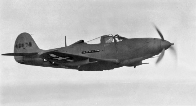
Occasionally though you do get the odd drawing that is almost impossible to use but having gained some experience in developing these aircraft structures it was not too difficult to determine the missing information.

This is the one I have for the lower section of one fuselage frame.