For the last 3 weeks I have been working on an update to the Bell P-39 Airacobra Ordinate and CAD dataset. The original P-39 was intended to be a personal study of the construction and structure and therefore never actually finished. However following a request from a good friend who asked if I could do some work on the Vertical and Horizontal Stabilisers I decided to have a look and see what I could do.
This model is brand new, effectively replacing the old model with a new direction in how these models are presented. The majority of the CAD/Ordinate datasets comprise extensive spreadsheets of dimensional data, drawings and a 3d cad model of the profiles. The idea is that all this data will provide the end-user with a number of options for their own projects. To develop their own models, from either the 3D cad model provided, the 2d drawings or using the spreadsheet data. Fundamental to all this is getting the core dimensions correct which was my primary goal.
I have extended that concept further by applying a base material thickness to the frames and ribs using the Sheet Metal function. For reasons of clarity it is just the basic web profile but what it does is provide the end-user with an actual solid 3d model; dimensionally correct. This can be further utilised for production or used for RC models with the basic frames in place.
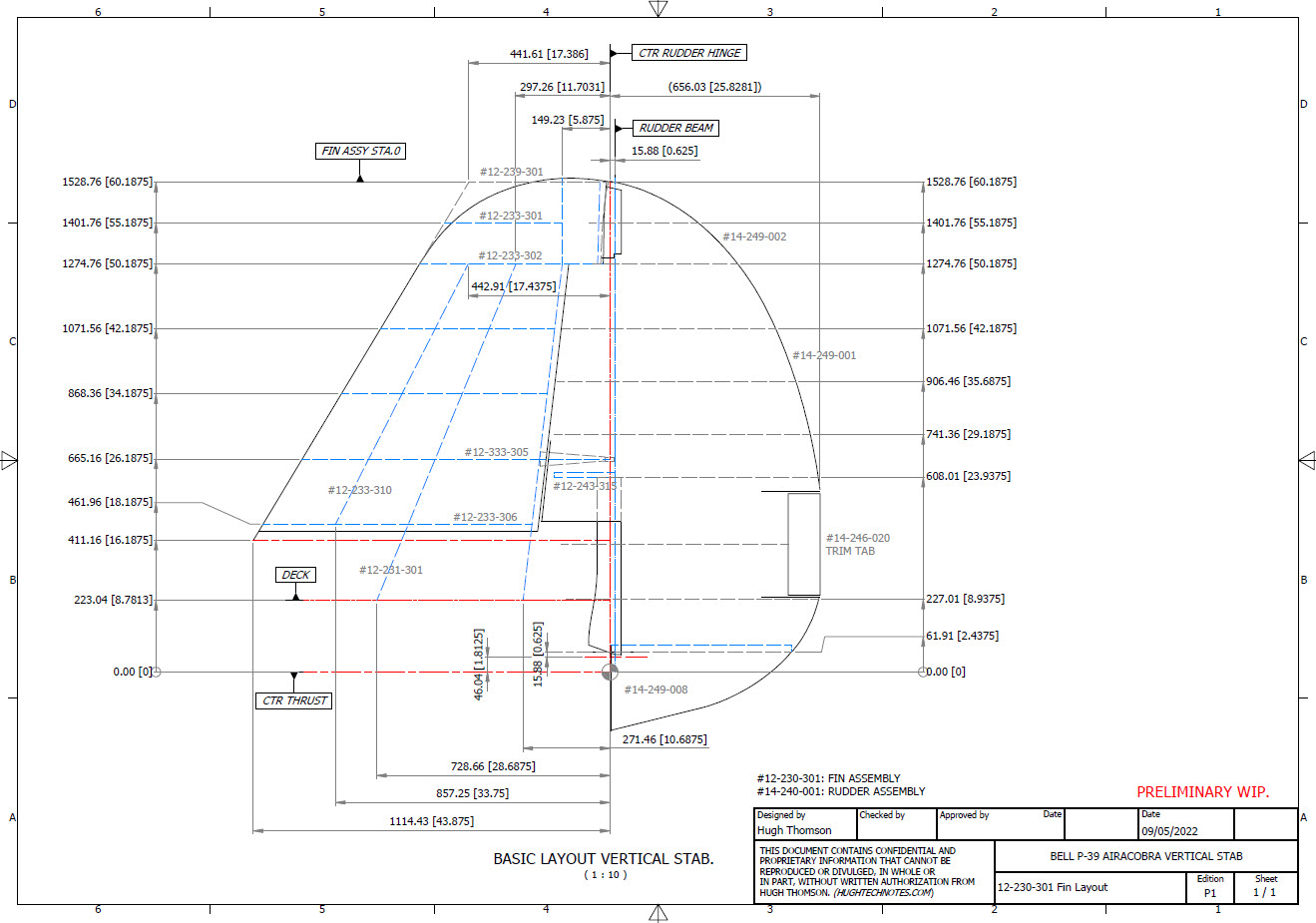
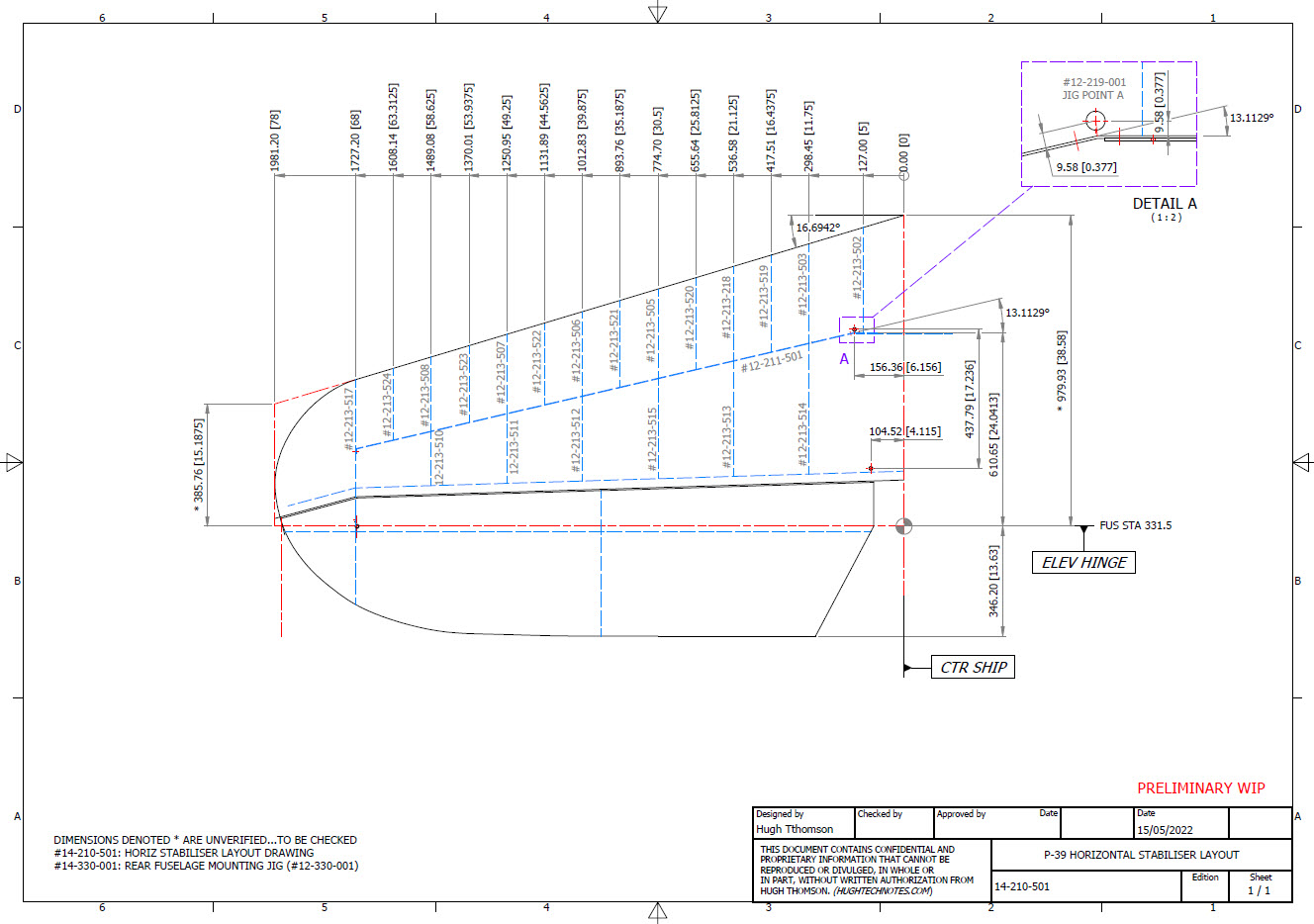
This development came about as a consequence of building the Horizontal Stabiliser. This was hampered due to a number of significant Bell drawings that don’t seem to exist as well as a few-dimensional error in the drawings I do have.
Developing this model required a lot of research to achieve the most accurate model possible for the P-39 Stabiliser. For example, the angle noted at “3” is defined on the Bell drawings as 13 degrees but when you check the layout against the Jig mounting points on the fuselage the angle is actually 13.1127 degrees. The material thickness of the ribs was an important factor when calculating this angle.
The dimension at “1” is not on the drawings but I did eventually find this quoted on a NACA Wartime report which aligns perfectly with expectations. The Leading Edge sweep angle is derived after I developed the LE ribs and aligned with known information. This is close and guaranteed to be within plus or minus 0.2 degrees. I have also written to a few companies that have P-39s to see if they are able to verify this angle. Update: Note the leading edge angle has been verified with a new value; see later post on this blog dated 12 July 2022.
The new P-39 Airacobra model and Excel spreadsheets are now online. Dimensionally it covers all aspects, wings, fuselage and empennage. There is also a copy of the old model which is still relevant.
Old Model (more 3d cad bits):
The plan is eventually to revisit the previous CAD Models for the other aircraft projects and add the web material thickness as I have done with the new study. This adds value to the potential use of these models far beyond what I initially intended.
As usual for more information drop me a line at hughtechnotes@gmail.com
I wrote an article on using the Ordinate datasets many moons ago, which is now rather dated so I figured it was time to write an update with a better explanation.
First of all the reason why? It’s like every other construction project where you first start with a skeletal framework and then develop the project’s envelope. Whether it be a building with a steel frame, a boat, even the human body relies on having in place the skeleton on which to build the construction elements.
Aircraft projects are no different and to this end, many manufacturers provide this information in the form of ordinate dimensions. This information occasionally is listed in tables or included on the individual part blueprint drawings. I firmly believe that once you have the basic framework dimensionally accurate then everything else falls into place…so it is incredibly important.
Basic Ordinate Overview:
Let’s take an example from the Bell P-39 Airacobra.
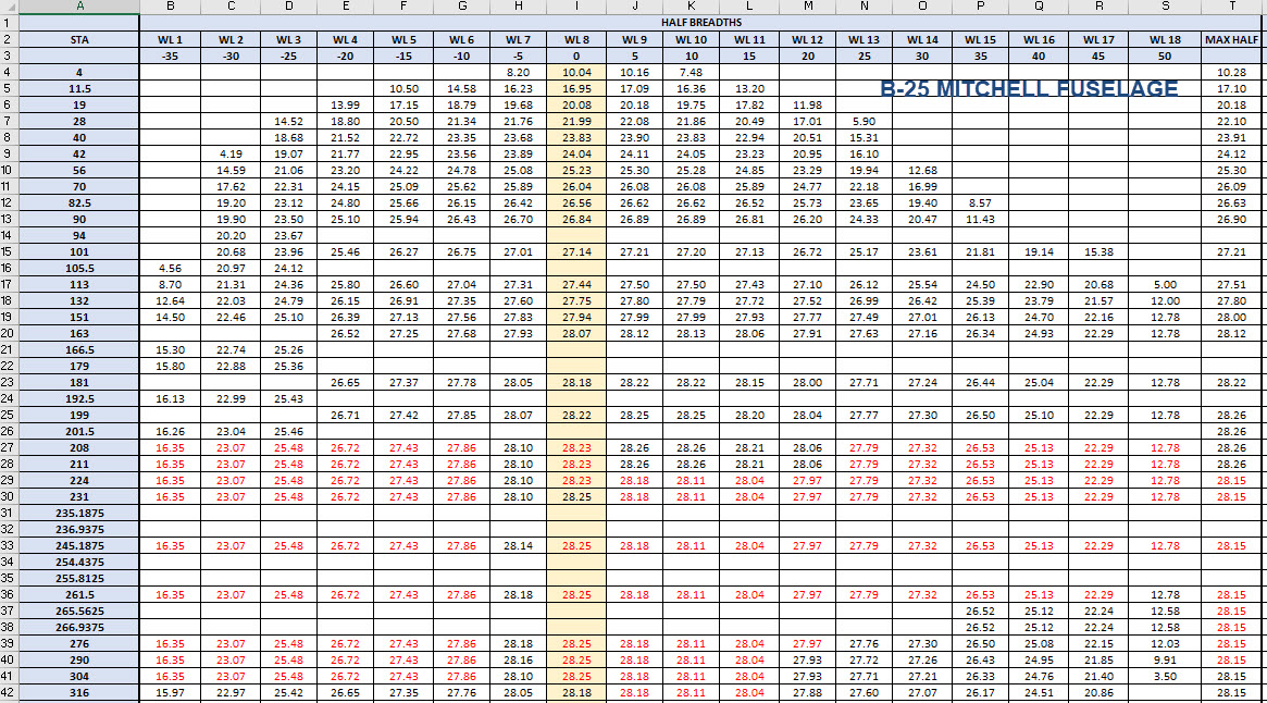
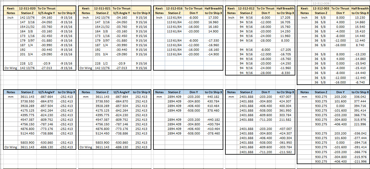
For this aircraft, the ordinate dimensions are noted on the actual part blueprints so I have developed a series of tables listing this information in excel spreadsheets as shown. They list the Station Location from the aircraft Zero plane (this is usually identified by the manufacturer). The Station number is actually the station dimensions from this plane which defines the Z component. The next column on the table is the Vertical Y-component or the dimension to the Waterline and finally, we have the Horizontal X-Dim which lists either the Buttock Line position or Half Breadth dimension.
Commonly the Horizontal axis on the aircraft is known as the Fuselage Reference Line (FRL) or occasionally the Thrust Line. The Vertical Line is simply known as the Centre of the Ship to the Aircraft.
Waterline (WL): Horizontal Axis, Buttock Line (BL): Vertical Axis. An example of this is where we commonly have a designation like WL4…which means the Waterline at 4″ above or below the Centre of the Fuselage. So when it is not specifically dimensioned you would know from the designation where it is located.
Once I have the tables of known dimensions I would occasionally extrapolate this data to list the actual X,Y,Z dimensions in separate tables to make it easier to copy and paste into any CAD system.
As you can see from the above image, the dimensions are initially listed in 3 columns, X,Y,Z and next to that is the same data listed with comma delimiters. The reason for this is because Mechanical design packages like Inventor and Solidworks will recognise separate columns of data in the requisite order as stated whereas Autocad will require combined data for Mulitple Point input as comma-delimited.
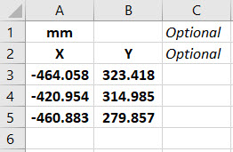
The way I do this is to have a separate excel spreadsheet which I keep on my desktop which I call Scrap.xlsx. The format is common as shown in the image on the left though I should note the top 2 rows are optional. If there are no units specified it will default to the CAD template units. I usually don’t bother with the top 2 lines. Once the points are imported into CAD I tend to delete the values in the spreadsheet Scrap.Xlsx and start again.
The comma-delimited column data in the above image can also be copied onto a Notepad Text file and used in Autocad. Worth noting is that if you try to import X, Y, Z coordinates onto a 2D sketch it will only import the first 2 lines and ignore the third…so make sure the columns are in X, Y, and Z-order.
An important consideration is that not everyone uses Inventor or Solidworks or even Autocad which is why the spreadsheets are critical because then everyone can use the data to build their own models.
Actually building the model can be done in several ways. You can build a part file with multiple workplanes on which to sketch the profiles from the input ordinate data or individually in separate part files. You can model the parts in context, i.e. taking into consideration the Station (Z-axis) dimensions so when input into the assembly they locate correctly in 3d space. Or just the X, Y, ordinates in the part file and locate to the Z-axis offset in the assembly.
Dealing with problem data:
This is perhaps one of the main driving initiatives behind the development of Ordinate datasets with regards to the legibility of the original manufacturer’s blueprints.
This example is actually quite reasonable whilst others are quite illegible. As most of these datasets are listed in Inches; which are normally factions; it is easy to confuse whether a fraction is 3/16, 5/16 or 9/16 when all you have is a blob of dark matter.
What I tend to do in these circumstances is develop what I do know and develop the profile using splines to connect the points and then apply the curvature to help determine the missing point location or check that a point is correct.
Occasionally points you need to complete a profile just don’t exist on the blueprints or are completely illegible which will then require more extensive research. Sometimes this information is included in the maintenance or Repair manuals or in the case of the P-51 Mustang a missing point was actually found in correspondence. Either way compiling this data and building the profiles is very time-consuming.
Another fairly common problem is wrong dimensions. Every aircraft project I have worked on from this era has this problem, not because they are bad draughtsman (very much to the contrary) it is because many of the drawings are only records of the Template Lofts and occasionally the dimension is recorded incorrectly. The skill is identifying that the dimension is wrong; it is unwise to assume that because something does not look quite right that it is actually a mistake. So you have to check with associated parts and layouts to be sure.
The image above is the Horizontal Stabiliser leading edge. The rib in blue (1) was obviously wrong because of a distinct kink in the curved edge, which when corrected aligns well with its neighbours. The one in red (2) also appears to be wrong even though the curvature looks fine the forward edge does not match with the projected alignment (I tend to use an Axis feature to check this). Before I apply any corrections I will check the part drawing and then the assemblies to determine if there is an error or if it is actually a design feature.
Locating Sketch Datum Points:
Creating workplanes for sketches as offsets from the primary X, Y or Z planes tends to copy the originating plane datum point which is not always where we need it to be when importing a series of points. The best option is to use the Parallel To Plane Through Point when creating a workplane as this allows you to select the point which will be the datum point on that sketch plane for locating the point data.
Some of the datasets are setout specifically to make it easier to input the data from the spreadsheet. For example, the extrapolated X, Y, and Z, coordinates for the P-51 Mustang wing have been compiled and calculated so they will input at the location of the 25% wing chord. This is assumed to be the logical setout point from the CAD World Coordinate system which saves you a lot of hassle.
If however, you have to create a workplane on an incline this option may not be available in which case you need to adapt the local sketch coordinate system to suit the required datum point.
In Inventor, you would right-click the Sketch in the model browser and select the Edit Coordinate System option which initiates an adjustable Coordinate icon on the sketch.
Suffice to say this icon can be manipulated, moved and rotated to any point on the sketch to suit your requirements. I will do a more comprehensive article on this shortly.
Other Excel Ordinate Examples:
The actual layout of the Ordinate spreadsheets depends entirely on the form from which the data is developed. Where the original blueprint data are listed in tables I will generate the excel spreadsheet in exactly the same format…which helps when checking the data input. If there are no tables but data from the part drawings then I will generate tables according to how the dimensions are noted.
All the dimensions are listed in Inches and Millimetres. I normally extrapolate the X, Y, and Z coordinates to millimetres as this is easier for me to work with…but it is easy to change that to inches if required. All the spreadsheets are fully editable and not restricted in any way.
Finally a quick Excel tip:
If you work with percentages a lot you will find this useful. When entering the value in the cell just add the % sign after the numbers and Excel will automatically format the cell as a percentage value.
Ordinate Data set Availability.
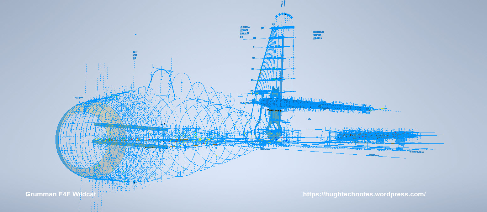
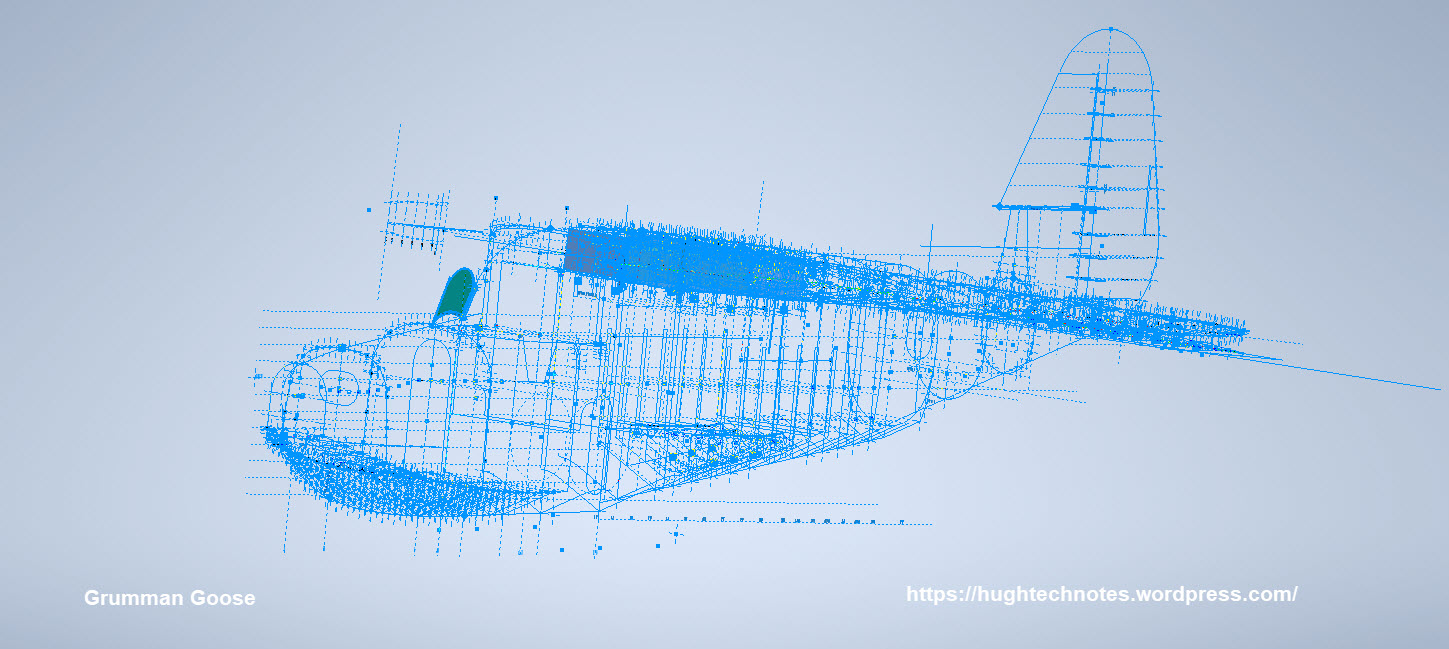
The NAA P-51 Mustang (probably the most comprehensive study) is available as a separate package from the Blueprints archive. The B-25 Mitchell is also a separate package and the Grumman Goose. The F6F and F4F are currently included in the Blueprint archive as they are not so well organised (work in progress) for now.
The Bell P-39 Airacobra is currently included with the blueprints but as I am now working on a new update this will shortly only be available as a separate package.
The P-38 Lightning is brand new and will not be available until June.
Final Note: All the Ordinate packages include the 3D cad model as developed in Inventor. This should not be an obstacle to anyone wanting to interrogate the model as a 30-day evaluation of the Autodesk Inventor is readily available for download. You can even extract sketches from the model as DWG files if required.
Many of the Ordinate packages include fully dimensioned Autocad 2D drawings and PDFs. These are mainly layout drawings and critical location information where it is essential to better understand relationships between wings, fuselage and empennage. Again all these are fully editable.
For all inquiries and feedback please get in touch: hughtechnotes@gmail.com
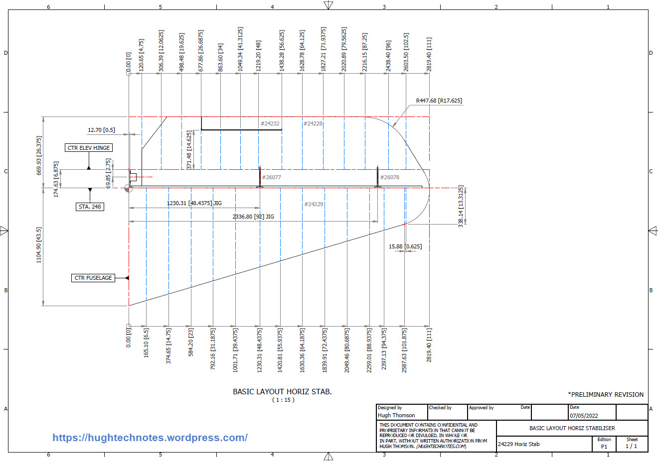
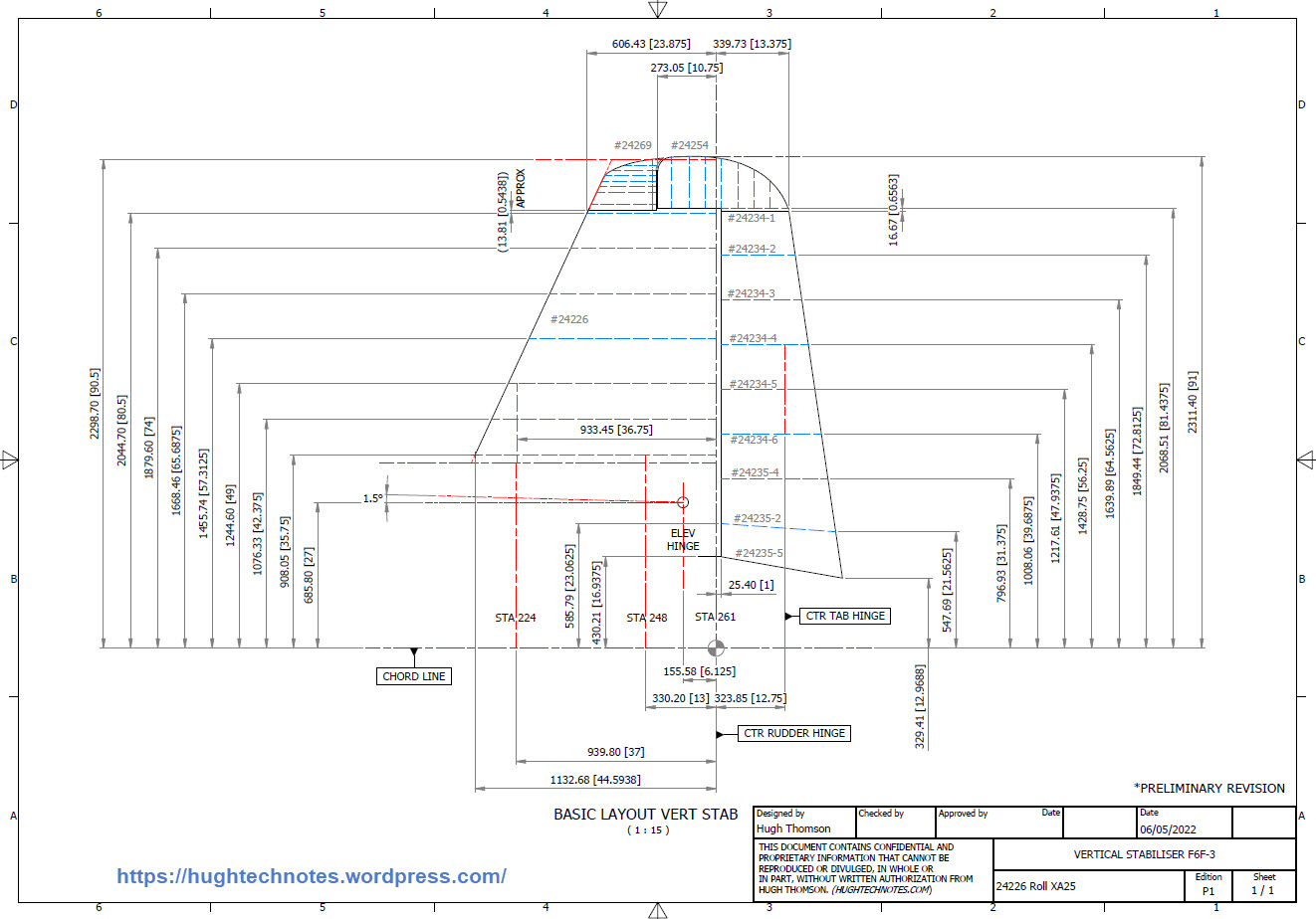
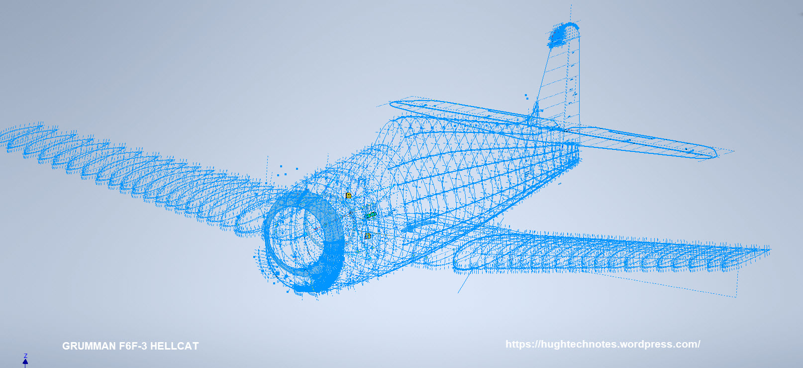
While I source new information for the P-38 Lightning I decided to revisit and update the Grumman F6F Hellcat and the Bell P-39 Airacobra Cad/Ordinate datasets. This work relates to the empennage for which I have decided to make the Autocad DWG and a PDF copy of these documents available for download.
These drawings are preliminary Basic Layouts for early release. The 3D CAD model updates will only be available to those that have previously purchased a copy from me directly. Though these won’t be finalised until nearer the end of May 2022. I shall contact the buyers directly in that respect.
I am also in the process of tidying up the Ordinate datasheets to make them easier to read. The datasheets list the ordinates for each frame/station profile in both Inches and Millimetres with a second sheet that extrapolates this data and compiles the data as X, Y, and Z coordinates for input into any CAD system. These X, Y and Z coordinates have initially 3 columns for each ordinate which is ideal for Mechanical systems like Autodesk Inventor plus an additional concatenate column which combines all coordinates comma-delimited for Multiple Point input into Autocad.
Other CAD/Ordinate Datasets:
These CAD/Ordinate packages are designed to help you kickstart your own projects. All the dimensional research has been done for you, which will save you weeks of work.
For more information drop me a line at: hughtechnotes@gmail.com
I can obtain a small number of key dimensions from the panel drawings which will not be enough to achieve an accurate full profile. I do hope someone has a copy.
I have tried all the usual sources for this information without success.
I can’t offer you much for the drawings but I am willing to share the comprehensive ordinate study and cad material when this project is complete.
Further Request: Photos of Wing Tip Required:
The wingtip trailing edge has a tab extension as a consequence of the connection of the top and lower panels. I am curious as to how this extension integrates at the extreme tip of the wing. If anyone has any close-up photos for the wing tip I sure would appreciate a copy.
Let me know if you can help. Email hughtechnotes@gmail.com
Update: 21st May 2022:
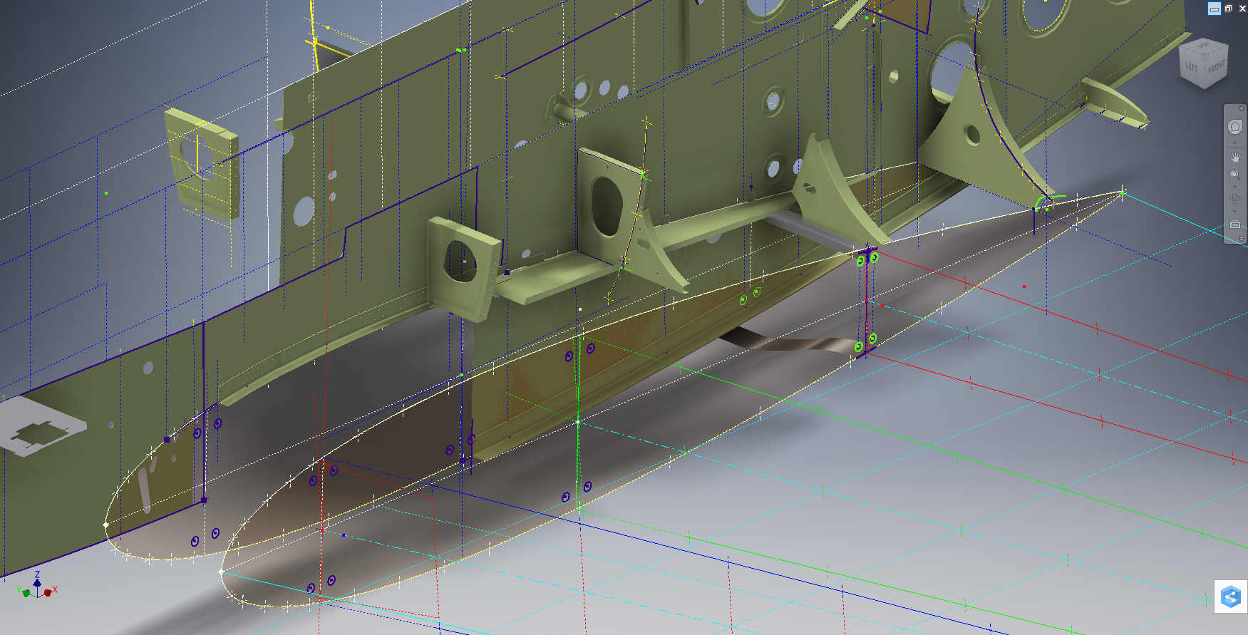
I have not had much luck with sourcing the above material. The Mold drawings would certainly have been enormously helpful in determining an accurate ordinate model. There is a Plan B, though it is going to be a fairly intensive search for every morsel of information that can be gleaned from the individual part drawings, manuals and reports that collectively will give me enough to achieve an accurate definition of the FWD Boom and Engine cowl surfaces.
An example would be the Scoop web plate profiles shown above to achieve some surface definition in those areas. I am currently working on the Landing Gear doors which will help define the lower surfaces. This is a lot of work which unfortunately means this will not be ready until much later in the year. I don’t do guesswork, if the ordinate point does not exist it is not on the model.
If anyone has any information that can assist me with these ordinate points, please, please do get in touch.
New Ordinate/CAD Project: The Lockheed P-38 Lightning is an American single-seated, twin piston-engined fighter aircraft that was used during World War II. Developed for the United States Army Air Corps by the Lockheed Corporation, the P-38 incorporated a distinctive twin-boom design with a central nacelle containing the cockpit and armament.
This project will dissect the complexity of the aircraft dimensions with fully developed spreadsheets, CAD models and drawings. I have drifted back and forth on this project over the last few months, studying the blueprints in detail to determine the best way of presenting the data in a usable format.
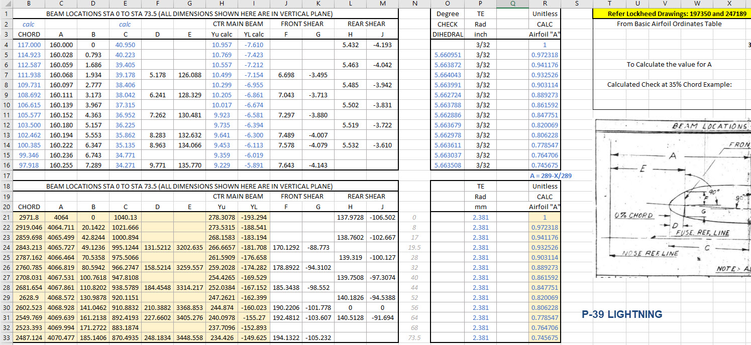
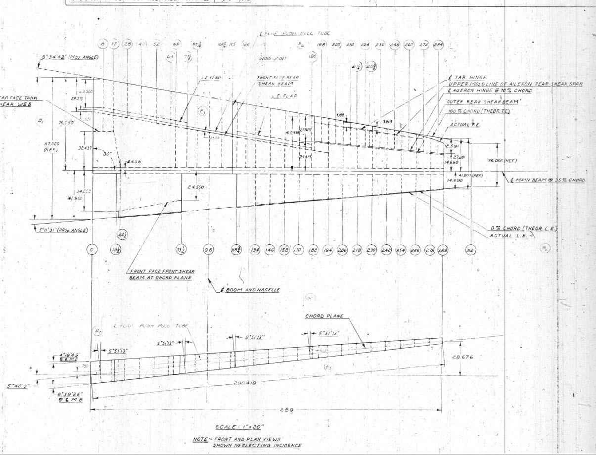
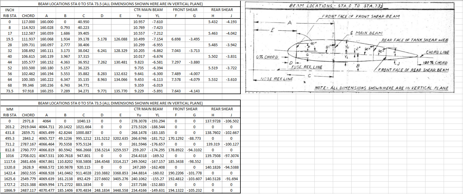
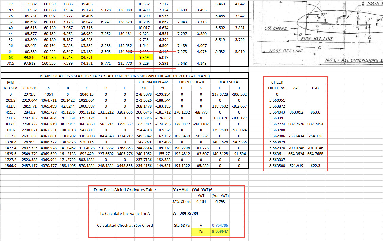
Surprisingly the wings are probably one the most complex parts of this study. The complexity comes about as a consequence of how the dimensional data has been recorded. For example, the wing chord is at a dihedral angle of over 5 degrees with the wing ribs actually perpendicular to the ground plane.
When we define the wing ribs we are actually working on a vertical plane angled to the wing chord line with the main beam and rear shear beams perpendicular to the chord on section. We also have the dimensions for the basic wing airfoil profile. Initially, I will record the rib dimensional information and generate the correct array of points at each Station. Then I shall calculate the airfoil profile at each station based on the given formulae Yu = YuT+(YuL-YuT)A. This should give us a means of verifying the tabulated data, for example; the table values for the Main Beam on 35% chord should match with the calculated airfoil values.
The plan is to record the dimensions as noted, vertical, horizontal and chord aligned in inches and millimetres exactly as defined on the original blueprints. Then I will extrapolate the X, Y, Z, coordinates for each point taking into account the chord angle of 2 degrees so that we can simply transpose these points directly into CAD at the correct positions relative to the origin point where the Nose Ref Line intersects with the Fuselage Ref Line.
The other caveat to all this is the 0% chord line is actually set back from the leading edge. There is yet another table of dimensions that relates the curvature of the leading edge to the 0% chord line. Ultimately to define the wing ordinates will involve a lot of work and then checking to ensure accuracy and correct alignment with the airfoil claculated profiles. At the end of the day, it is about making sense of all this fragmented information into a workable solution that makes it easier to interpret and use in any CAD system.
This is essentially how I work with all these Ordinate/CAD datasets. It is not just about recording information but also to check that the information works and that the end-user can transpose this into whatever system they are using. It is quite common for the information on the blueprints to be obscured, missing or simply illegible which usually requires a fair amount of time searching for answers. To complete this project I estimate something in the region of 300 manhours.
Update: 26th April 2022:
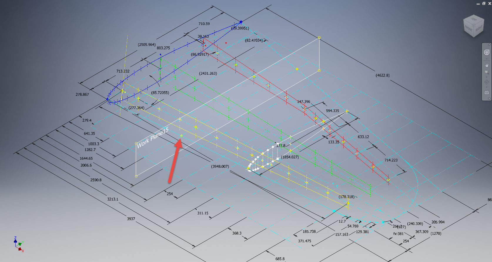
I have not yet decided on how best to present the Wing Ordinate dataset. I am looking at establishing check tables that will effectively compare the noted tabulated dimensions on the Blueprints with the calculated values. Also, we need to derive locational information directly from the wing plan CAD drawing for the Rear Shear beam and do a calculated check. Just to give you some idea of where I am going with this see screenshot below. As I mentioned above, the information on the drawings is fragmented so it is important that the excel spreadsheet data is presented in a clear and legible manner. Just now it is a bit of a muddle.
A quick update: Have rearranged the spreadsheet now with calculated values in lieu of listed values so the CAD model will be considerably more accurate. Calculated values are in blue text.
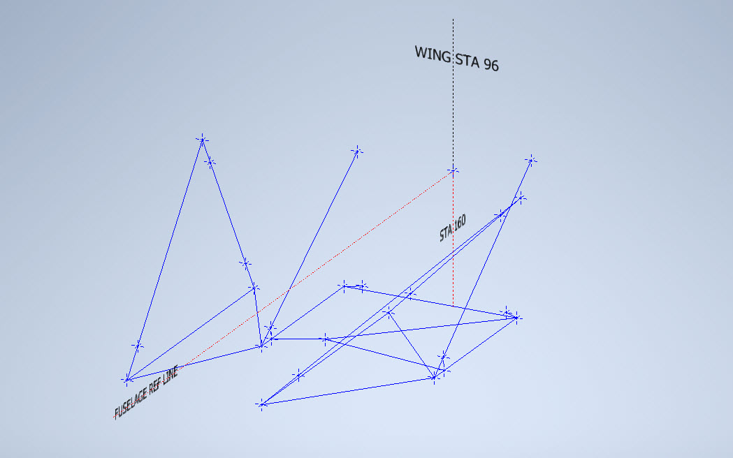
The rest of the Rib station tables will be added with similar calculated values and then I shall create a second worksheet with the airfoils for each corresponding station. The final sequence will be the extrapolation of 3D Ordinate points from a single datum so it will be possible to build an entire wing just from one collection of X, Y, and Z coordinates in one step. At least up to STA 254…still need to figure out the intricacies of the wingtip geometry.
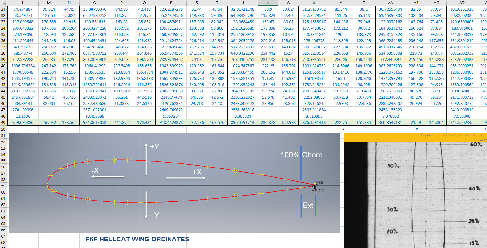
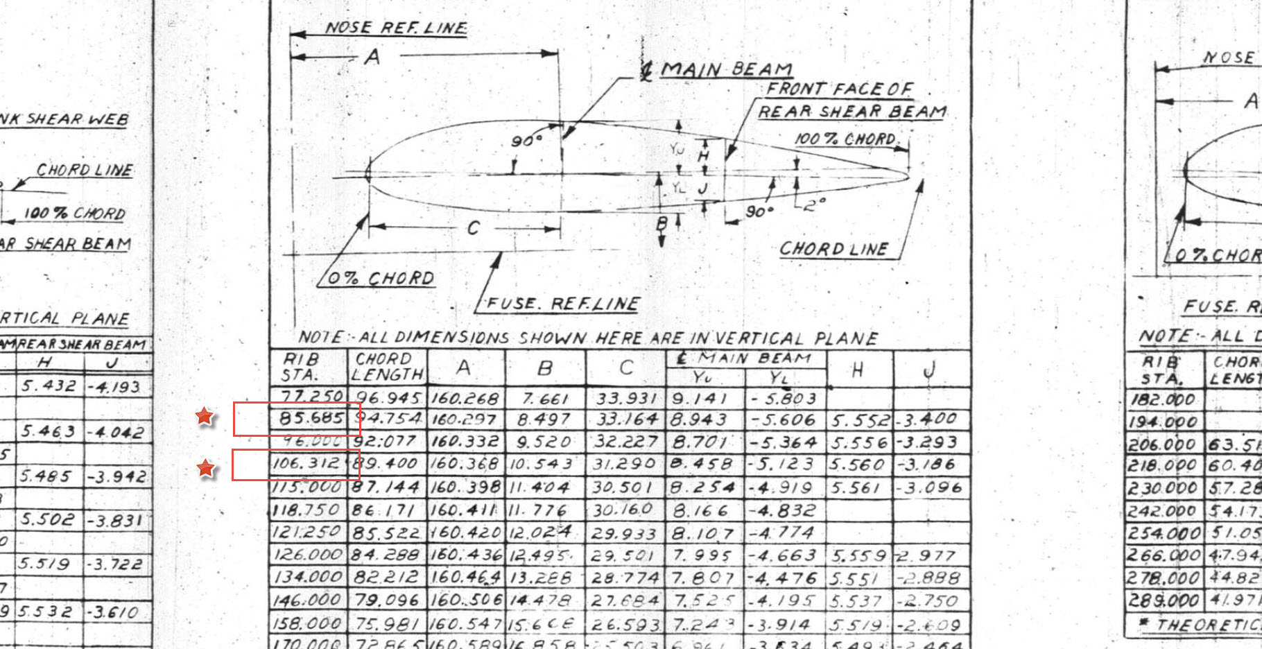
Ordinates for each wing STA profile are calculated and recorded as shown. The highlighted rows at the 35% chord, are checked with those corresponding values listed in the tables above from the Lockheed original drawings. By the way, the drawing on the right is the Basic Layout Engine Mounts…there are 2 variations on this; both of which will be developed.
In the above screenshot, I have highlighted 2 minor corrections to the wing rib locations. They should be the decimal value for 85 11/16″ and 106 5/16″.
Update 3rd May 2022:
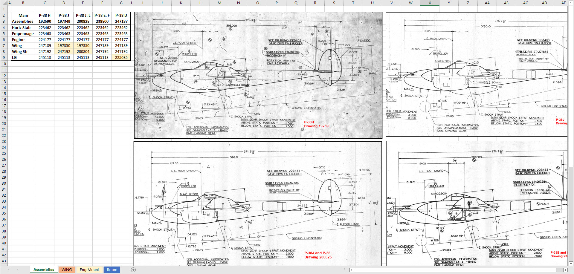
Have made good progress on the datasets for the Wing, Boom and Engine Mounts. Whilst working on this project I thought it may be prudent to compile an assembly list for each aircraft type for the basic dimension layouts as shown below. I plan to do a Technote shortly updating work methods using the ordinate dataset from Excel spreadsheets and include information on Sketch coordinate systems; manipulating the X, Y, Z-axis locally…so look out for that.
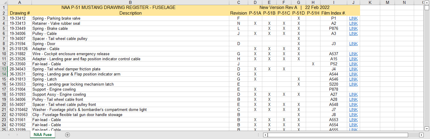
There seems to be a theme developing here…following on from my efforts to organise the chaos of large blueprint collections I endeavoured to continue my efforts with a long-overdue update to the P-51 Drawing register.
The P-39 Airacobra register was a breeze by comparison to this P-51. That was only a matter of 4-5 hours of work which was aided by the fact the drawing filenames were already fully described…all I had to do was add the Film Index numbers alongside the filenames. The P-51 on the other hand only had obscure filenames that were somewhat inconsistent…which meant this exercise ran into a few days. Occasionally my enthusiasm tends to thwart common sense!
Getting back to the P-51 Drawing register. The update is now inclusive of hyperlinks contained within the excel spreadsheets that will open the associated drawing. This is a huge step forward in managing and working with such a large archive and though it took ages it is a major improvement.
As you can see LINKS have been added to the right column (J) with hyperlinks recorded in column L. This column is hidden but can easily be viewed by using the option to UNHIDE. The Film Index reference is the actual microfilm reference hard coded onto the original film which differs from the actual filename that was generated when the film was scanned.
I should note at this stage that a number of folders in the archive will require renaming as Excel does not like #hashtags in naming conventions. The download section includes a word document describing the file-naming convention.
The hyperlinks are plain text entries originally copied from the development process that utilised the Vlookup function referencing a separate spreadsheet. I had considered including the separate spreadsheet in the download section but I think that just over-complicates things. About that development process!! It may be prudent to provide a quick overview of how things were developed.
The Development Process (briefly)
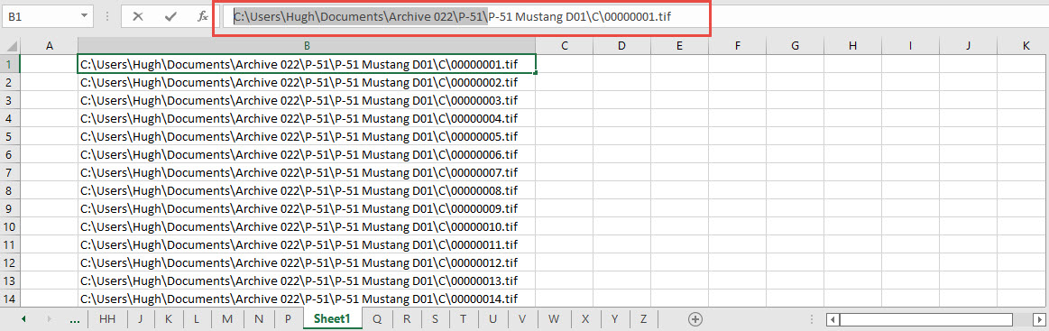
The initial process was to extract the filenames from Windows Explorer and deposit those records into a separate spreadsheet. The way to do this is to select all the files in the folder and click the Copy Path option in the windows explore toolbar.
Paste this into a spreadsheet and then remove the first part of the path (highlighted) so the location parameters now become a relative path to the root folder. This was done using the Replace (CTRL+H) function by copying the highlighted portion and applying a null space to all of the records.
This is now the actual hyperlink path which we need to associate with the actual Film Index. As mentioned above the Film Index is recorded on the scanned images and therefore a fair amount of manual intervention is required to record this value in column A. Using the Vlookup function necessitates that we use the column on the left for the value sought to return the value on the right. As you can see from the many tabs on this spreadsheet I filtered out all the filenames from every folder and then proceeded to populate the column in each case with the Film Index number…that drove me nuts!
There are several ways of accessing the values using Index and Match or even Indirect in conjunction with Vlookup…but we shall stick with the simple option of using Vlookup.
The Vlookup function asks for an initial lookup value; in this case “I10” then it asks for the corresponding Table Array; essentially the array of data from which to search. In this example, the array is defined as the values from the spreadsheet called “FILELIST” Tab “A” from cell A1 to B1043. The “2” refers to the column from which to extract the value you are seeking…which refers to the second column. “False” is for an exact match to the value in I10.
The Link is simply the =HYPERLINK function referencing the value in column K with a text value defining the label “LINK”.
You can combine the HYPERLINK function with the VLOOKUP in one formula like this…though it does take a fraction longer for the link to open.
That’s the basics of how this was done. using Indirect in conjunction with Vlookup enables you to search for the tab designation from a tab list that would look through the entire spreadsheet for the sought value. I didn’t think this was necessary for this exercise.
I mentioned the folder name changes that are required for this to work. The 3 main folders should now be changed to P-51 Mustang D01, D02 and D03.
The updated drawing registers will be available for download this evening so watch this space for an update.
As usual, the spreadsheets are fully editable so you can adapt the data to suit your own requirements. I would note that the Vlookup formulae are not embedded within these drawing registers as the hyperlinks are just copied text values and not live links. The recordset “FILELIST” is not available for download but if you would like a copy to play around with Vlookup or similar then please just drop me a line.
Update (earlier than expected)
The updated P-51 Mustang Drawing Registers are now online and available for download. Please let me know any comments or feedback.
This folder also includes the Aviation Manufacturers Standard Parts file which I am trying to consolidate as they tend to pertain to more than one aircraft.
Comments or feedback as usual to hughtechnotes@gmail.com
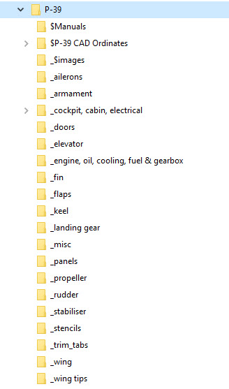
Another project that is long overdue is a drawing register for the P-39 Airacobra. This will be an Excel spreadsheet complete with drawing number, description and a link to the actual drawing file.
Assuming you have the P-39 folder arrangement as default the links will work fine.
The spreadsheet contains multiple worksheets each designated according to the folder name. The names are tabbed along the bottom to open each worksheet. The links will open the connected file in Adobe Acrobat so make sure you have the Acrobat Reader as a minimum.
The spreadsheet is still work in progress which hopefully will be available for free download this evening. The spreadsheet needs to be deposited in the root P-39 folder.
The spreadsheet is fully editable so you can adapt it for your own project. I should note that columns G and H are temporarily hidden columns that contain the hyperlink address…so don’t be alarmed when they suddenly pop up when you are developing your own adaptations.
To HIDE or UNHIDE a column, select the column header, right-click and select the option from the menu.
Every aircraft manufacturer has libraries of standard parts in addition to the MIL specs that are used for their various aircraft designs. These vary considerably covering a wide number of standard parts like bolts, nuts, washers, hinges, screws, grommets, extrusions etc, etc.
When I was working on the P-51 Mustang Tailwheel mechanism I was forever jumping back and forth looking for the various standard parts which was a nightmare due to the large number of files in the archive. This was further complicated as the file names were the scan numbers and not the drawing names. So I figured it was time to get this stuff organised.
I have worked through the archives for the Grumman F4F Wildcat and F6F Hellcat and extracted the Standard Part drawings and renamed them with the correct drawing designations. I have also done a similar exercise for the NAA P-51 Mustang.
The actual drawing filenames have been adjusted slightly to make sorting easier (by group) and make the names more legible. Where for example we have 1E48; this is denoted as 1E-48…the 1E is the alpha-numeric group designation with the numerical sequence suffix. This just makes it easier to read when you have hundreds of files in the same folder.
The excel spreadsheet is a register with the different manufacturers’ part drawings listed on separate sheets in one workbook. This is tabbed along the bottom of the spreadsheet. It is envisaged that each set of drawings as listed will include a download link to an online resource to access the files. This download link for the collection of standard part drawings is located on the top right of the spreadsheets.
The NAA Part Drawings also include the previous specification identifier as some of the earlier blueprints still refer to this number.
This is an evolving project and will be continually updated as more information becomes available with the inclusion of other manufacturers data. Currently, over 400 part drawings are registered. For further information please drop me a line at hughtechnotes@gmail.com.
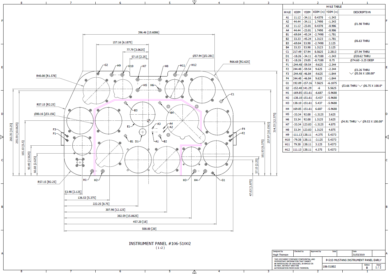
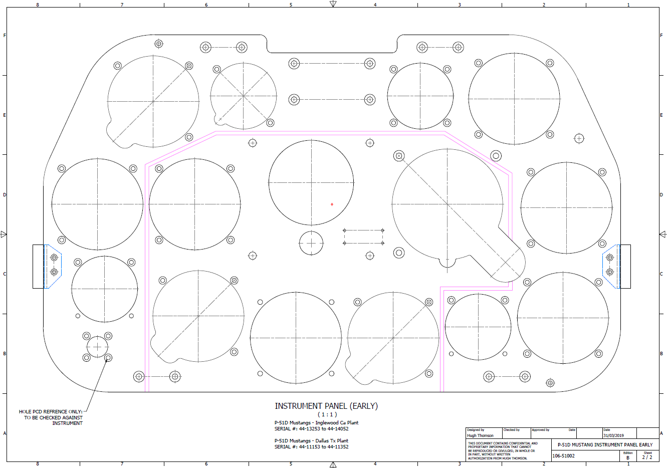
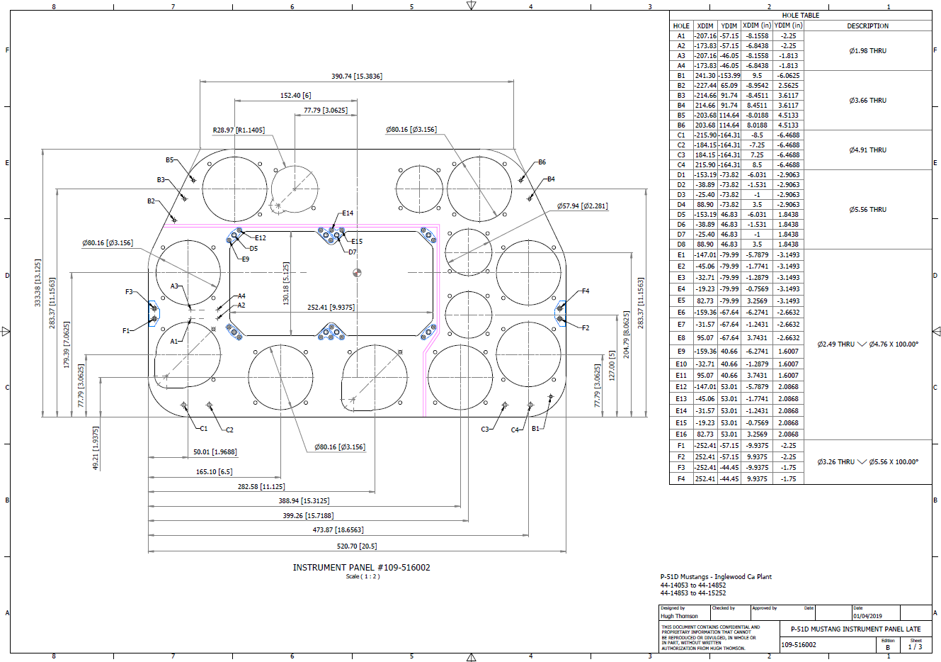
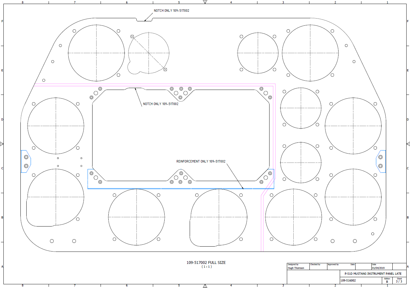
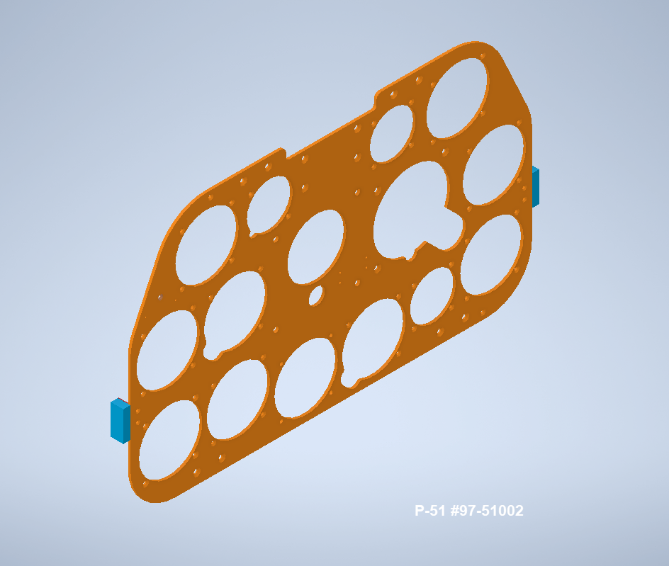
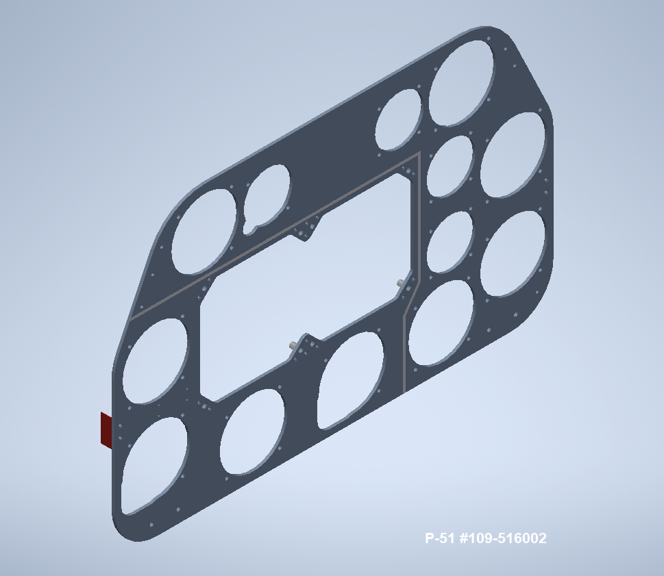
P-51D Mustang: 3D Instrument Panels: Updated 11 June 2022
P-51 B and D Instrumentation Panels are now available online as a separate package. This package includes all below noted Instrumentation Panels 3D CAD models in STP, STL and 3D DWG formats with associated dimensioned 2D drawings and PDFs. Note the hole positions are listed in a tabulated form on the drawings which can be extracted for CNC work.
Also included is a copy of the original NAA instrumentation drawings for reference.
Update 20th June 2022: All Instrument panels now also include the Parasolid X_T format. The complete package is available for download, get in touch at hughtechnotes@gmail.com.
Early Version P51D: 106-51002
Later Versions: 109-516002, 109-517002
Update 15th Feb 2022
For P-51B Mustang: 97-51002
3D Model Views:
For further information drop me a line at hughtechnotes@gmail.com.
Occasionally when trying to Emboss text in Inventor the command will fail. Most likely the problem will relate to intersecting lines for the font style..invariably it will tell you why it doesn’t work.
This can be very frustrating with few solutions other than reconstructing the font style would be apparent. However, there is a way to resolve this…well at least the particular font I am trying to use for the P-51 Mustang instrument panels. In a previous article, I had opted for an alternative to the MS33558 TTF as this font style is flawed.
I have now found something more compatible and it is called TGL0-17 ALT. This is actually very close to the MS font…however I have still encountered problems.
The solution is to first open the text editor in Inventor and select the font type, set the height, width and spacing. You may need to select Exact for the latter and type in a value to achieve the correct spacing instead of using the defaults. Once you are satisfied with the formatting close the text editor and try to emboss it. If the emboss fails move on to the next step.
Select and open the text editor again and this time highlight all the text, then copy and paste this into MS Word as Text Only. Refresh the font style by selecting an alternative and then select again the TGL0-17 ALT. Copy and paste back into the Inventor text editor, close it and voila now it will emboss.
Before you ask, I have absolutely no idea why this works only that it does in this case So next time you have a problem embossing text in Inventor try this workaround and see if that works for you.