In 2016 I submitted a white paper with supporting videos and images with a proposal to create a World Heritage Image Libray for an International competition sponsored by Virgin.
Around that time ISIS went on a rampage systematically destroying many historical buildings and monuments In Syria. It is unfortunate we are again witnessing similar atrocities in Ukraine with the terrible costs of human life and the destruction of so many Heritage buildings and monuments in this terrible war.
As an engineer, I often think about the infrastructure and buildings lost and ponder the issues of reconstruction. I have written to our leaders in the UK Government to be proactive in establishing funding and resources specifically to act quickly to help Ukraine rebuild. However, as usual, the cogs of government take a long time to turn and this does not seem to be a real priority for them.
Getting back on topic. The paper I submitted for the International competition outlined a method to address the issues of restoration and reconstruction where Architectural and Engineering documentation was limited or none existent… which typically would relate to historical buildings and monuments.
The idea was to develop an International Digital Image Library of photographs, film, paintings, sketches and illustrations which would be a single resource for reconstruction purposes and if in sufficient quantities could be used to create digital 3d models through a process known as Photogrammetry. Photogrammetry is the art and science of extracting 3D information from photographs. The process involves taking overlapping photographs of an object, structure or space and converting them into 2D or 3D digital models. The library should be an online portal for global submissions with an option to be able to send in the raw format whether that be film, paintings, sketches or illustrations for the purpose of scanning.
I would envisage a global appeal to photographers, artists, filmmakers and visitors (tourists) that would have taken photos or created works of art of global historical buildings and monuments that have been destroyed by war, natural destructive events or have simply been eroded over time. The idea of a global library would yield considerable quantities of images in various formats that would be invaluable to any rebuilding effort.
I recently wrote to the Ukraine Embassy proposing this same idea, though more specific to the Ukrainian situation. They are currently promoting the “Postcards from Ukraine” campaign which features before and after images of buildings affected by this conflict. I had hoped they would consider this suggestion as an addendum to their current campaign.
As I haven’t heard back from them I thought it may be worthwhile sharing this idea and see what you think. Ultimately a Heritage Image Bank needs to be a global initiative. In many ways, this would not be too dissimilar to the rationale that established the Svalbard Global Seed Vault.
I mention in my Bio that I used to indulge in Photography which I got into in the late 70s. In those days it was mainly portraits, fashion and hairstyles…I did okay and had many images published at that time. I ventured into many fields of photography throughout the years; including industrial; which of course was an advantage for me also working as an engineer…I had ready access to exciting material.
Photography though was always a part-time interest, something I was passionate about but not something I pursued commercially after my stint in the late 70 and early 80s (even then only part-time). Actually, when I got married and had kids the focus was entirely on them; which of course was amazing times. I photographed everything and everywhere we went as a family…great memories.
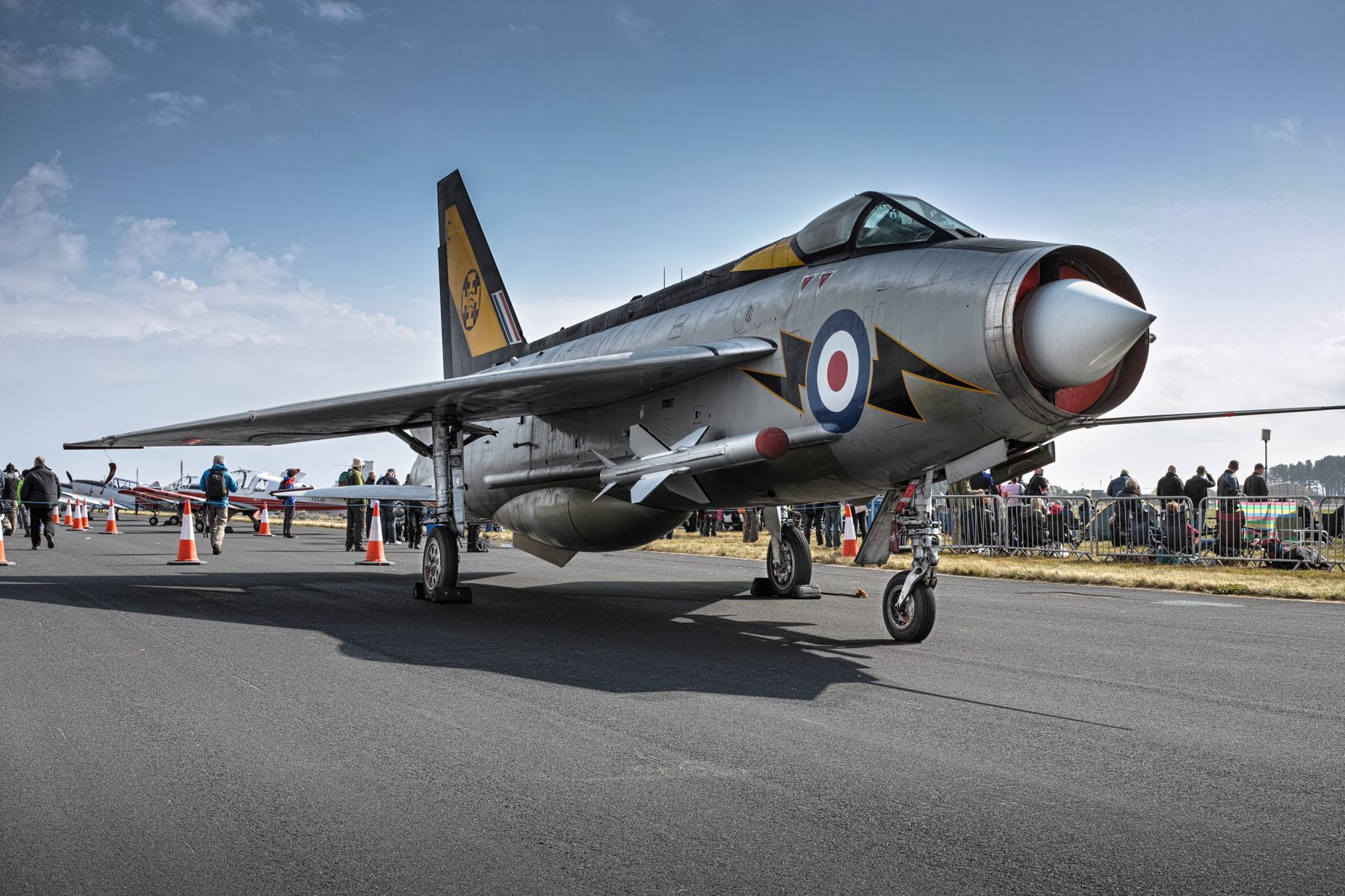
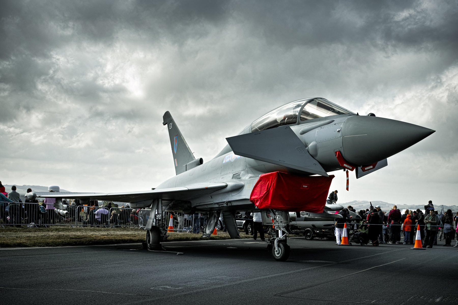
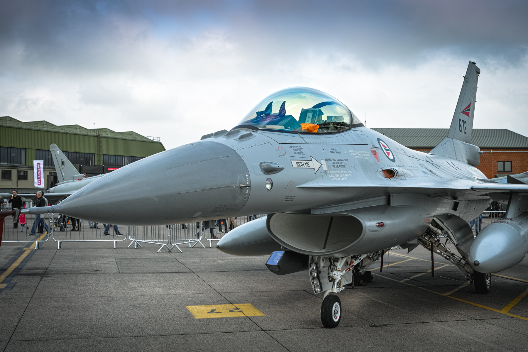
I also enjoy photographing aircraft. These were taken at RAF Leuchars in Fife, Scotland at the last ever International Air show before the base was transferred to the army in 2015. These were all taken with the Sigma DP2M camera…one of the Foveon sensor range of cameras. The Sigma camera was legendary for the incredible detail they could capture, though admittedly they were a real pig to use!
I will look through the archives and process some more and include them in future articles here. I have these online and are available for download here…full-size images (roughly 4704×3136) in Jpg format.
Technote: Steel Coke Plant: Using Regression Analysis:
Slightly off-topic this may be of interest to those working in the Steel Industry, particularly Coke Oven Plant machinery. I worked in this industry for a few years before being made redundant when the company closed operations.
This company for some reason were unaware of this technique which is one of the reasons why I wrote that blog article as others may also find it useful. An exert from the article:
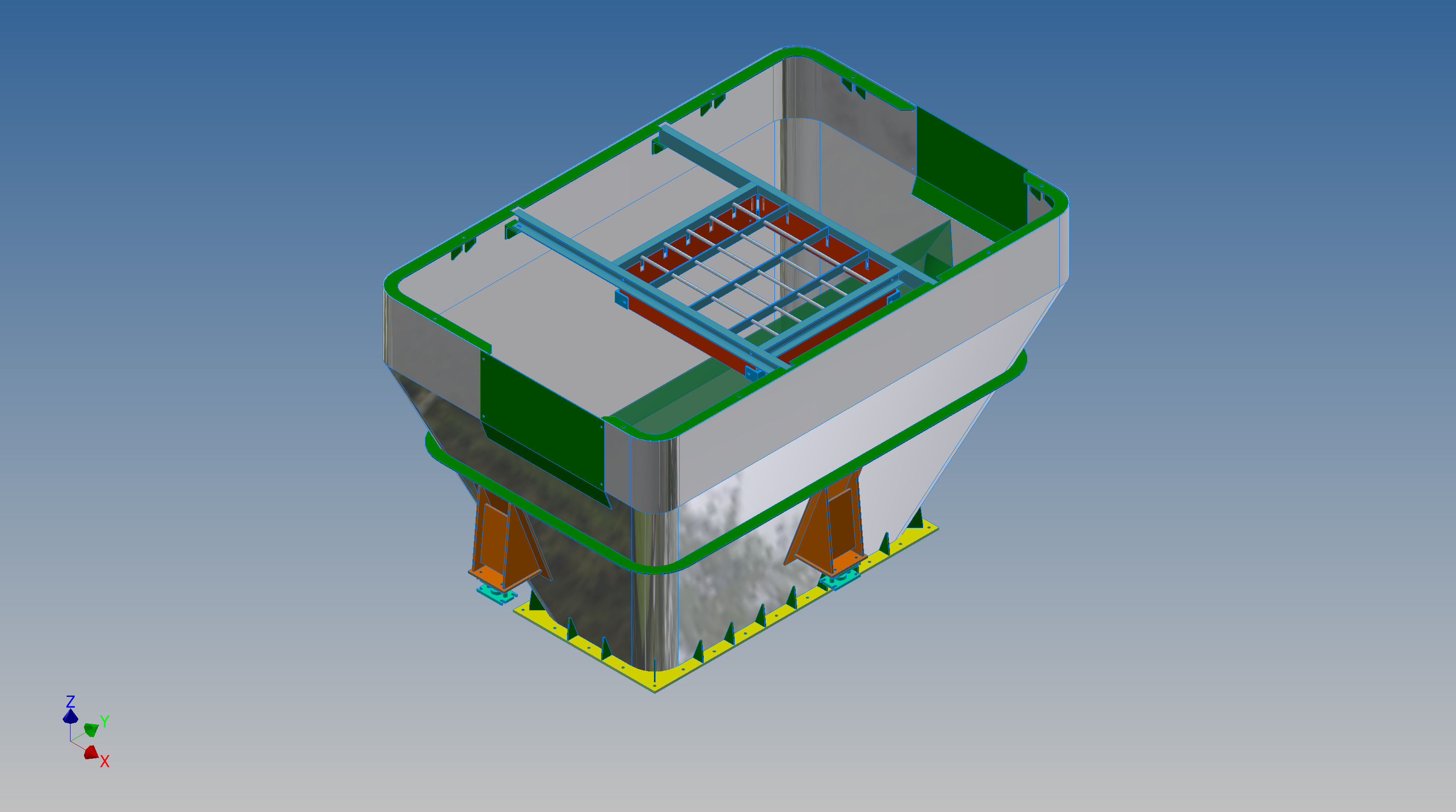
“This type of hopper is fed from an overhead bunker and releases the fill material through an aperture in the base. The mass volume is modelled according to industry specifications that define the slope of the poured coal defined by the size of the top bunker opening.
The surface represents the containment boundary which has zero volume and zero mass therefore by definition will ensure that the only properties recorded for mass and volume in the 3d model relate only to the fill material.”
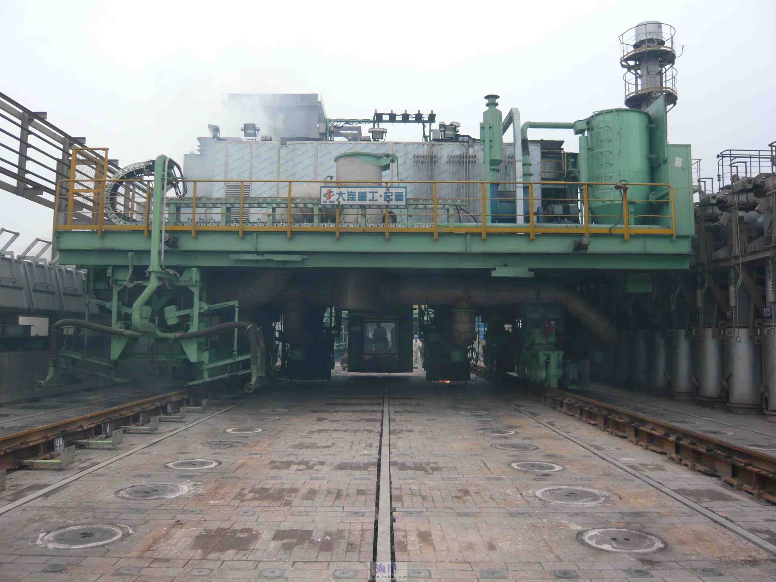
The type of machinery used to service Coke Ovens is extraordinarily large and heavy; that runs on rails not too dissimilar to trains. These images show examples of Transfer Cars that essentially transfer coal stored in overhead bunkers to the ovens below.
These machines work in a very corrosive environment and are often replaced with new vehicles after many years of service. A prerequisite to designing is to commission a fully detailed survey of the track rails and surrounding constructions, which provides the basic criteria and envelope parameters to define the design’s physical restrictions.
In this article what I am talking about is related to the rails on which these vehicles will run. As you can imagine after decades of use they tend to shift alignment and are never truly straight and in line. So it is important to have these correctly surveyed in order to determine the ideal location for the wheel centres on the bogeys. Before I started with this company the way this was done was simply to average out the survey information to achieve a suitable centre line on which to locate the wheels. I figured there may be a better way, so I introduced them to Linear Regression Analysis, which essentially does the same thing but more accurately.
Oddly enough the array of points shown in this Linear Regression Analysis is very similar to a survey plot of rails. It, therefore, was a logical progression to utilize this same technique to determine the Best Fit Centre Line for the Coke Oven machinery wheels.
I did this for a number of projects in each case establishing the linear regression for both tracks and in turn defining a line equation from which to extrapolate the ideal centre line. Because the 2 tracks were separate components the line equations would be slightly different with both rails not necessarily being parallel at any given point. So what happens next is to essentially repeat the process this time finding the ideal best fit line between the tracks and then checking in CAD to see how the vehicle would run.
I termed this process as Crabbing, essentially checking the determined centre of the vehicle and therefore the wheel centres along the length of the Liner regression track lines. There is obviously some adaptability built into the bogey designs to account for track variation and it is the purpose of this exercise to determine whether we could achieve movement of the vehicle within the requisite design parameters.
This is also a technique that can be used to optimise ordinate profiles where accuracy is critical. When you think about it most dimensional data points are specified to an accuracy of 1/32″ or 0.7mm which is normally within acceptable parameters however for greater accuracy why not try using linear regression analysis?
It was a useful technique and worked very well. So next time you need to determine the best fit line within a range of static survey points perhaps consider using Linear Regression to help achieve the desired results.
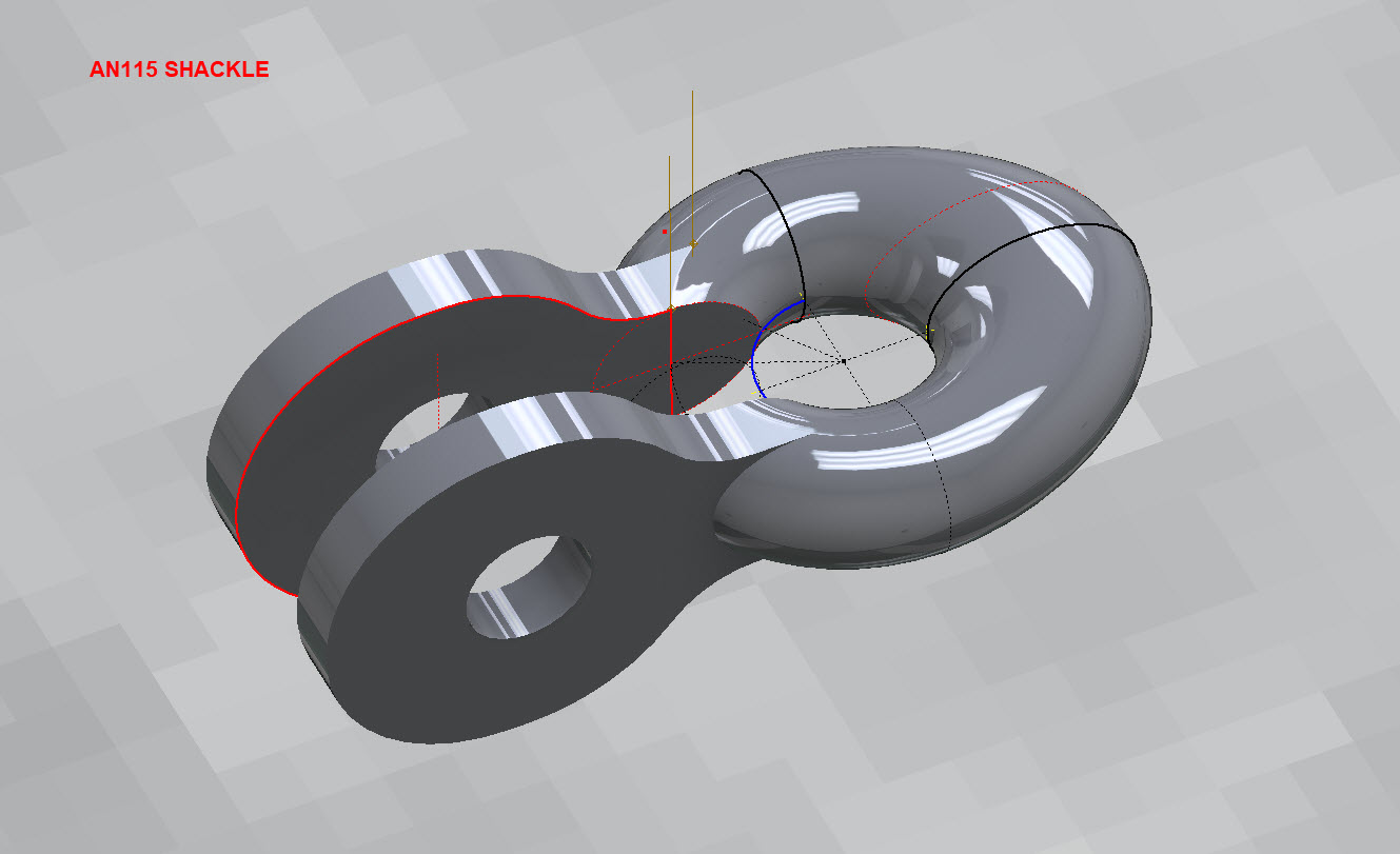
Working my way through the various AN Standard components I thought it may be prudent to write up a quick Technote on modelling the AN115 Shackle.
At first glance, this seems to be a fairly straightforward item to model, however, getting the transition from the flat section to the curved ring is rather tricky. When you view this item on Google and look through the various images of the finished product there are visibly small variations in how this has been interpreted. Needless to say that I have my own interpretation to achieve a smooth integration while ensuring the integrity of the finished model.
First of all, ignore the bulge on the right-hand side…for some part numbers this area is elliptical and not round…so for development reasons I have purposely exaggerated the profile to test the iPart creation.
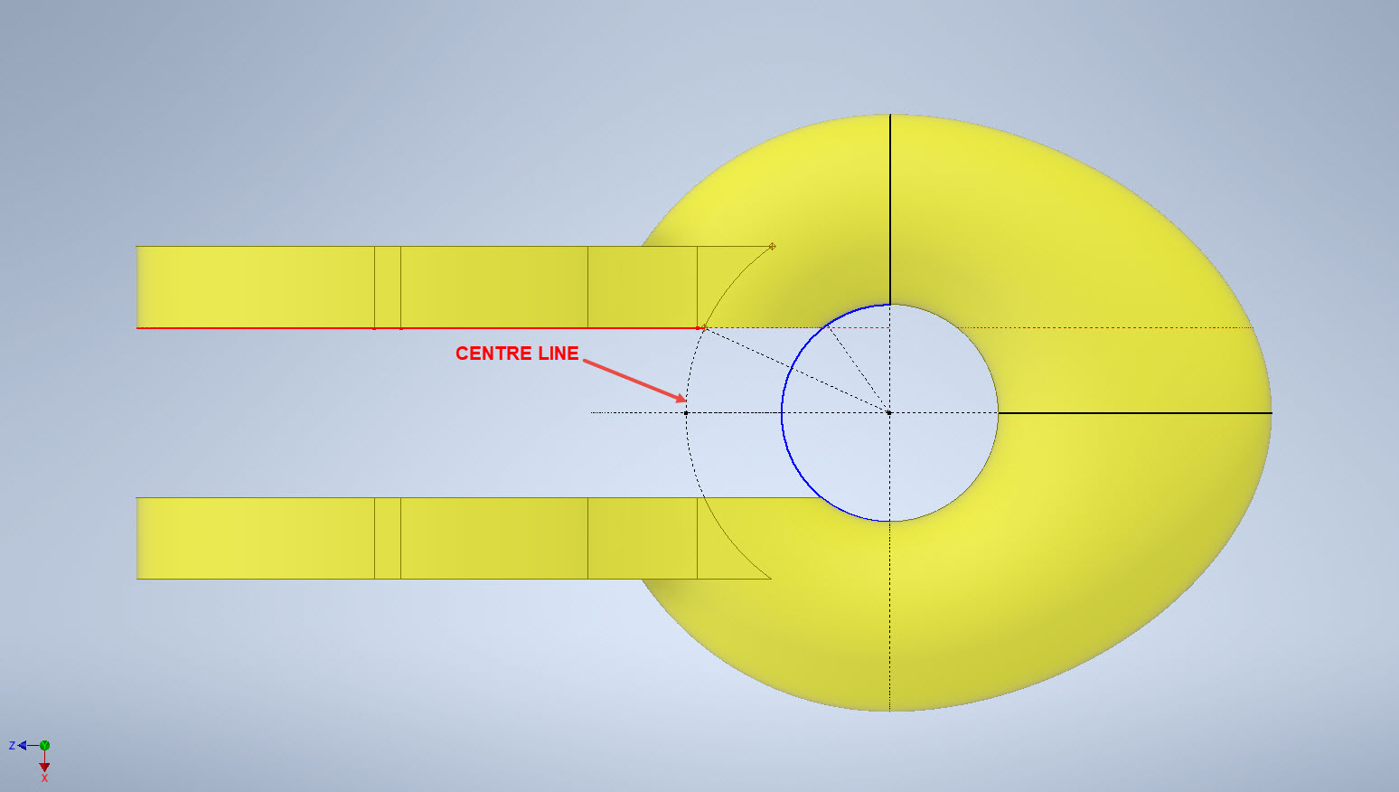
What I was looking for was to achieve a smooth transition along the edges of the flat portion to merge with the round profiles of the ring section. My first attempt was simply to have a curved edge at point “1” that was tangent to the ring and the edge of the flat section. However, that did not achieve a good result because the top and bottom surfaces of the flat section coincide with the ring at different points which created a small twist when lofting the sketch profiles.
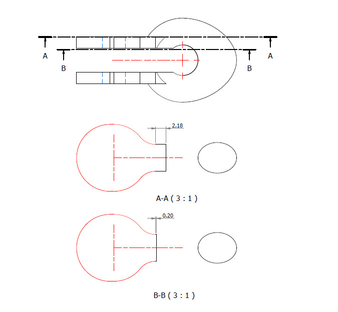
I found the best way of solving this was to introduce a small horizontal line tangent to the ring section profiles. For the inner sketch, this was only 0.2mm which translates to just over 2mm for the outer sketch. The points shown as “1” and “2” are the centre points projected from the ring centre line which is the start point for those sketched horizontal lines.
Now when we loft the 2 sketches we have a good square edge for the flat section…by the way, I should note that the flat section is initially lofted as a separate solid because we still have one step to do before we merge the solids into one. After lofting the flat sketches we still have to trim the resulting solid to follow the centre of the ring surface.
This is simply done by extruding a surface from the centre line of the ring as shown and then trim back the excess from the flat section model. Now we merge the 2 solids and we end up with a shackle that has a smooth transition from flat to ring without any twists or surface anomalies.
The bulge is still there on the final image…that will be gone once I finish filling out the table with the various part number dimensions.
So sometimes when you are modelling a complex item like this it often helps to introduce a minor feature (in this case a small 0.2mm line) to ensure that lofting and extrusion activities provide the desired end results.
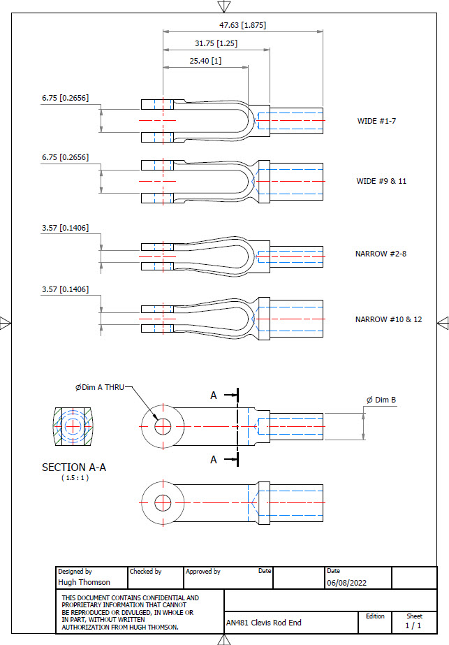
AN481 Clevis Rod End:
Another tricky item to model is the AN481 Clevis Rod End. There are 4 variations on the same model that comprise 2 sets each with a narrow gap and a wide gap. Technically it is possible to create all variations in one part file and use Suppress and Unsuppress options to exclude or include features…however, I decided not to do that because it can be a real pain adapting the model if the regeneration does not quite work the way one expects it to. The model is not that complicated so it was just as easy and to be honest much tidier to create separate part files for each variation.
As usual for further information please get in touch at Hughtechnotes@gmail.com
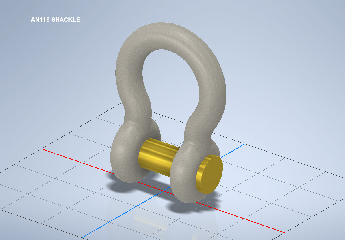
AN116 Shackle:
The AN116 Shackle PIn is shown with a rounded head which I decided not to model due to the lack of detailed information for this pin. I tend to shy away from modelling components where there are no specific dimensions. I am not sure this is critical except where accessibility for tightening the pin is a consideration.
The new Parts Library should be finished at the end of August…I will advise.
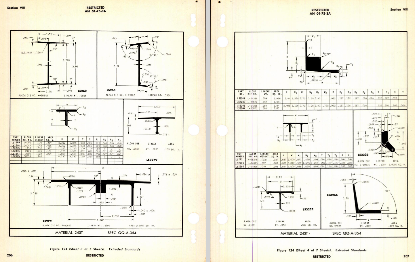
Many moons ago I started a project to develop libraries of Aeronautical standard parts according to the various National and International standards pertinent to aircraft design and maintenance noted in this article.
Using the original standards from the wartime era and the updated, often replacement standards, I figured it would be a good idea to develop this project further. I am aware that there are many different CAD systems so it would be folly to just develop this for just one product.
The above products are currently available in the Resources Tab of this blog and though included with the Mustang P-51 Ordinate/CAD dataset are standard for many aircraft of this era and accordingly are available separately. This existing collection is already very comprehensive with over 300 parts modelled and listed, though these are in line for an overhaul and update.
Moving forward with this project I will develop the configuration spreadsheets exactly as per the original specification tables set out plus any additional dimensional data that will be required for modelling. This will be accompanied by a DWG file as a template to use when developing your own equivalent of an iPart. Essentially putting together a dataset that anyone can use regardless of what CAD system they are using.
Additionally, standard metal work profiles will also be developed and produced in a similar manner.
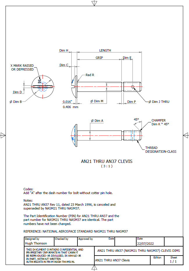
There is a catch: This will take a while to do and probably won’t be ready until October. Typically the study will comprise a basic dimensioned drawing exactly as per the reference Standard with accompanying spreadsheets. There will be separate spreadsheets for each part number in a collective Standard, though there may be only one drawing. For example AN21 THRU AN37.
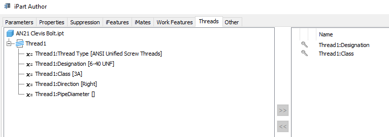
The way to use this dataset; regardless of the CAD system; is to first develop the part model naming the parameters as defined in the spec (you can use the DWG for your sketch template). In this example, the first 2 columns are generic to the specific CAD system with the first column being a unique value. From LENGTH to Dim P, in the table, these are the main geometry parameters. The Hole1 column has values “Suppress” or “Compute” which is an instruction to exclude or include the hole. The Thread parameters are defined as a Designation and Class which are standard integral parameters; those names may vary accordingly. Typically in Inventor, they can be found in the iParts Author as follows:
Once you have your Part modelled, open the iParts author and set up the first line of the table…you just need the first line at this stage Close the Author and open the table in Excel and copy the contents of the provided spreadsheet data tables above… ignore the header/titles. The iPart table will now be updated with all the above variations. It does not matter if your part template is Metric or Inches as the part dimensions are predefined as inches and will automatically recalculate depending on your template standards. You can of course already do this with the existing iParts but they are not inclusive of dimensioned drawings…so you have a bit more work to do referencing the actual standards for parameter names. That’s what this project work is designed to do…essentially finish with full documentation.
These spreadsheets and CAD profiles will enable anyone to very quickly develop a standard library in their own CAD system…an important resource and time-saving endeavour. I should note the actual AN and MS standards are available online for anyone that wants to access them. I have provided a link below to my previous article on this subject.
Blimey, this is quite an awesome task…I envy those that build the standard libraries in the many CAD systems that contain thousands of parts…this will definitely take a long time.
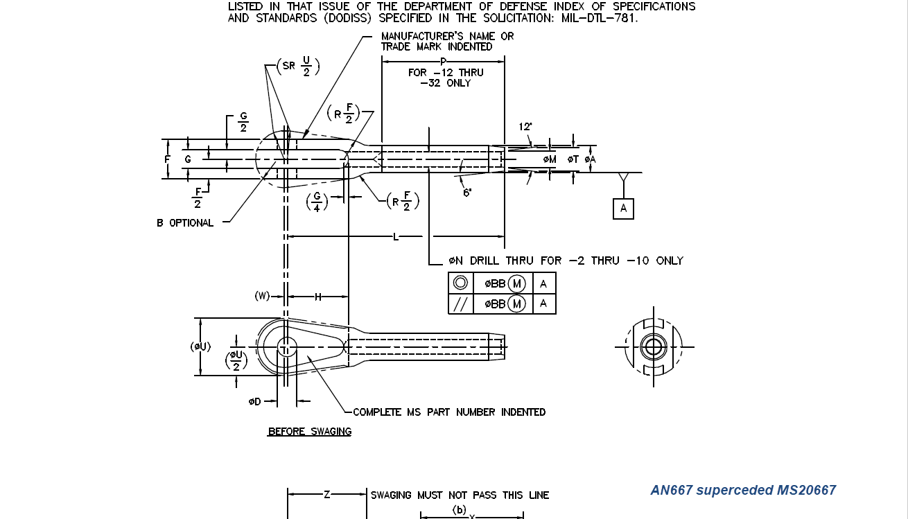
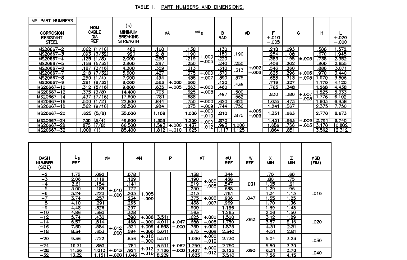
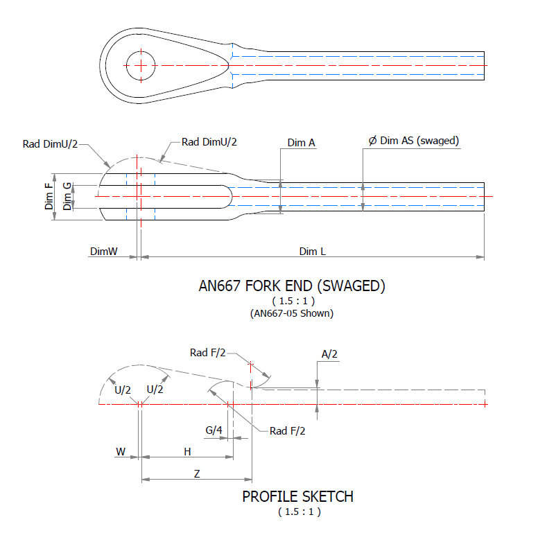
Many of the parts are relatively straightforward like Bolts, Castle Nuts, Clevis Pins etc that require nothing more than basic dimensioned drawings. Occasionally though many parts will require additional sketches to clarify the profiles, like this AN667 Terminal Fork End. Also in similar cases, the model will be dimensioned to As-Fitted/Swaged for use in assemblies. You can basically ignore the Scale as all the DWG versions of these drawings will be 1:1 according to the part number actually modelled.
This is a list of the Specifications I am currently working on. Many of these are updated versions of the existing standards available on the CAD Resources page. The updates include marginal improvements to the 3d models, additional data and verification of listed dimensions. The data sets also include dual part numbers where an item has been updated to a newer standard the new designation is noted alongside the old.
It is very important to get this stuff right, to ensure the part designations and representations are correctly defined in the assemblies. Have you ever tried to figure out assembly configurations from the NAA assembly drawings or picked your way through the Parts catalog just to identify a single connection for a clevis, nut and bolt, turnbuckle or whatever…it is time intensive. It was this desire to bring clarity to these assemblies that I created the P-51 Mustang cad models shown below, which incidentally was the catalyst that drove the development of these Part libraries.
Get in touch with any inquiries at the usual email. hughtechnotes@gmail.com
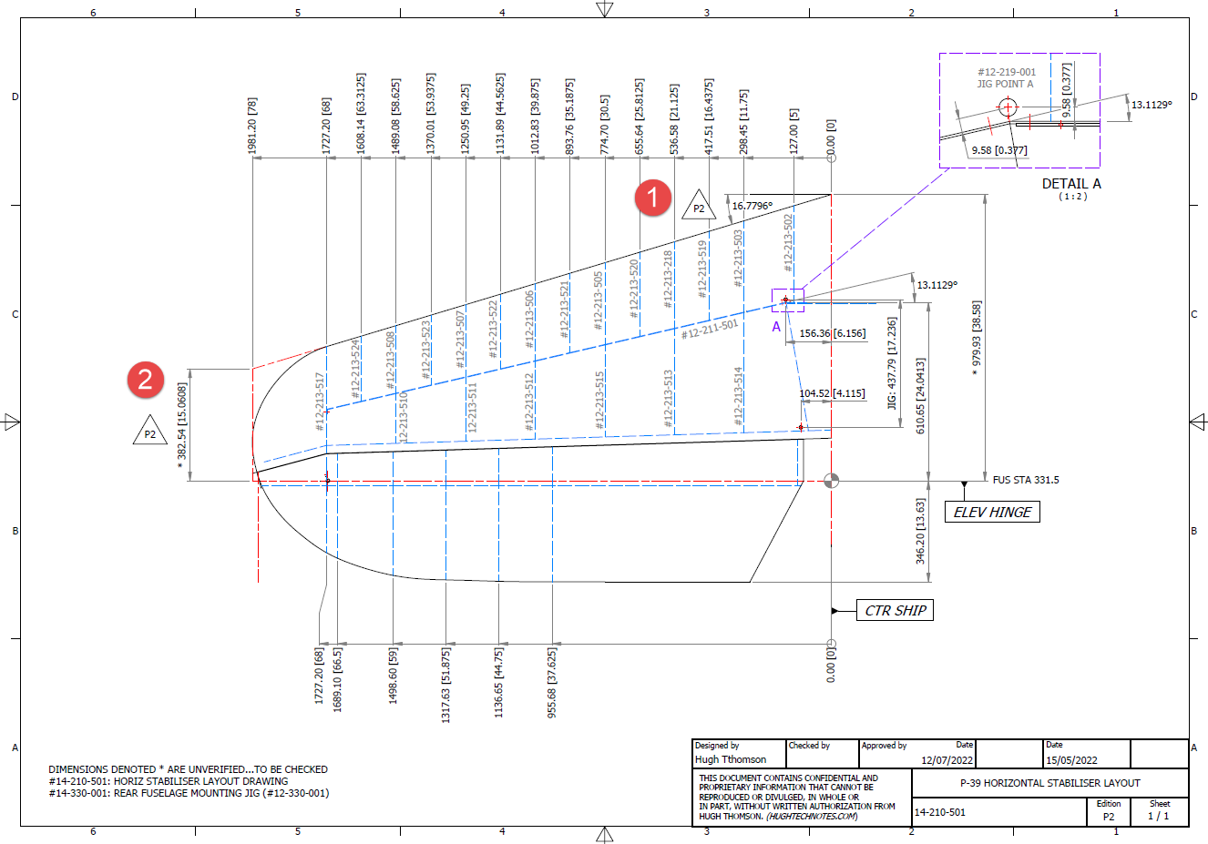
In a previous post, I covered the significant new model for P-39 Airacobra. This model is fully inclusive of all aspects of the aircraft. Within this post, I mentioned the extensive study involved in determining the layout for the Horizontal Stabiliser; the dimensions of which were unclear in the available blueprints
I was particularly keen to establish verification for the leading edge angle and though I had written to a number of organisations that have the P-39; surprisingly none of them took the time to either acknowledge or indeed reply…which of course was disappointing. From my experience, the industry is normally very supportive with regard to technical inquiries.
I revisited the documentation I do have and established that relevant information was included in the NACA Wartime Report L-602 which gives the chord length at Sta 49.25. It turns out; from my initial assessment; that the dimension at “2” was barely 2mm out and the Leading Edge angle is now 16.7796 degrees.
I mentioned in my last post that this latest study is available now which also includes the original model; which was more of a 3D modelling exercise than a dimensional study.
The P-39 Airacobra new CAD/Ordinate study is an impressive project.
All inquiries as usual to; hughtechnotes@gmail.com
Dividing a sketch line in Autocad is very straightforward and the question is often asked how this can be done in Inventor. There are a number of options to do this which I will explore and then I will discuss an application where the solution is not so obvious.
Where you have a known length and you wish to locate a point at 20% of the LENGTH it is simply a matter of applying the formula “LENGTH*0.2” for the dimension value. Another option is when you want to divide the line into 5 equal portions then you can use the RECTANGLE Pattern command. You first set the number of points, expand the dialogue and select FITTED; you will then need to select the line dimensions or measure as I have done here for the value.
Another way of doing this is to draw five line segments in succession and apply an equal constraint to each one. For the above; the length is a required parameter, so what do you do when you don’t actually know the length?
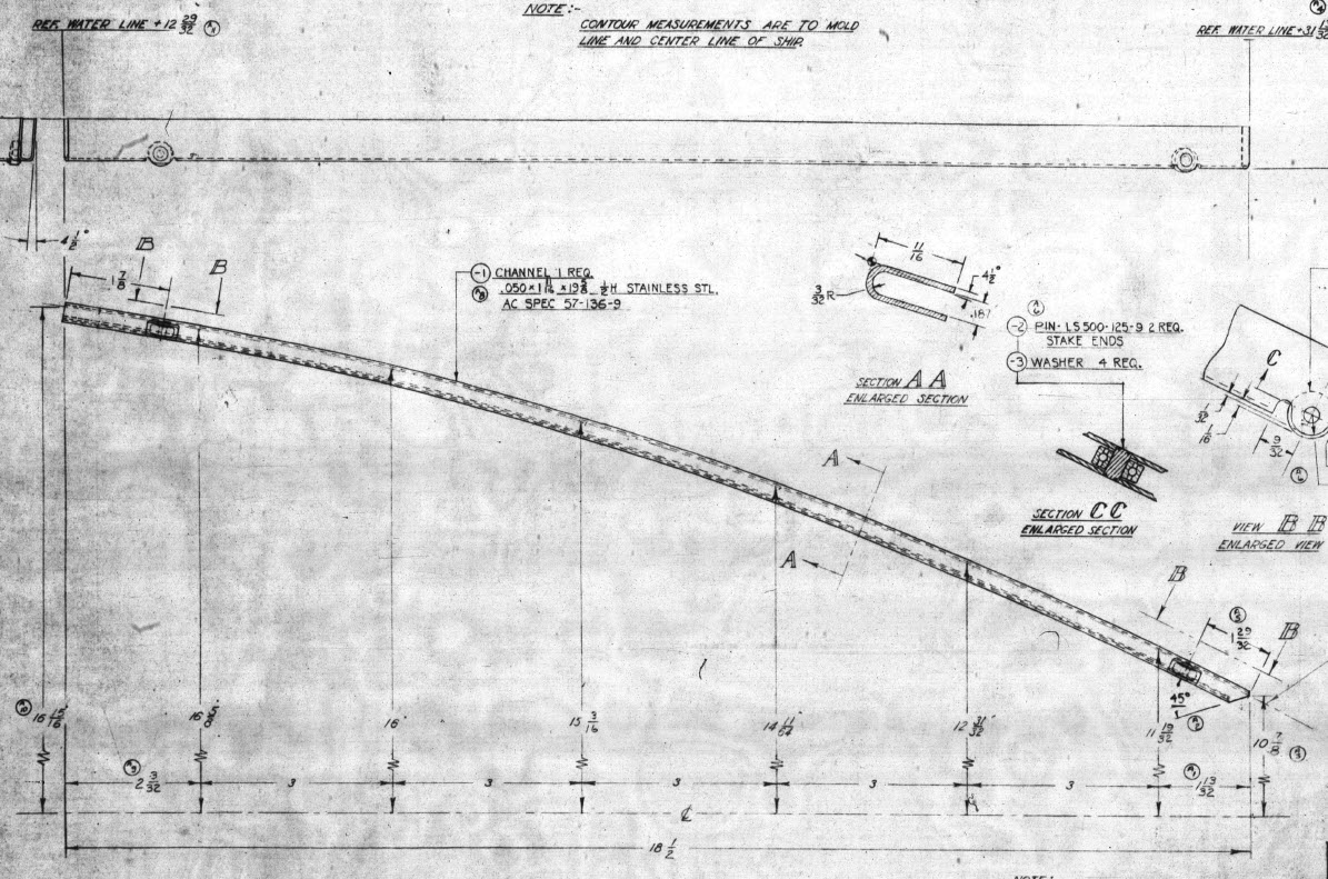
The following example is the P-38 Lightning Horizontal Stabiliser tip for which I wanted to document the ordinate points for the ribs. The ribs perpendicular to the stabiliser axis are known dimensions based on the standard profile however I also needed to record the profile dimensions of the ribs set at an angle to the main axis. Admittedly the Lockheed archive does contain a number of ordinate profiles for the canted ribs where unfortunately the majority of dimensions are illegible.
I like to record numbers so it should come as no surprise to those that visit this blog regularly that I was keen to tabulate the ordinate profiles for these canted ribs. The above image shows a number of magenta profiles which are the rib templates illustrating how the surface converges towards the tip extents. Incidentally, the diagonal lines on the main rib profile actually have a purpose…as you view the stab tip on the elevation you will notice that the ordinate points (projected) align with those diagonals.
Getting back to the main subject. The wing rib and horizontal stabiliser ribs follow industry-standard percentage increments for defining the ordinates as shown in the following image. Now we are getting to the main topic…where I wanted to transfer the ordinate locations for the perpendicular ribs to define the ordinate profiles for the canted ribs.
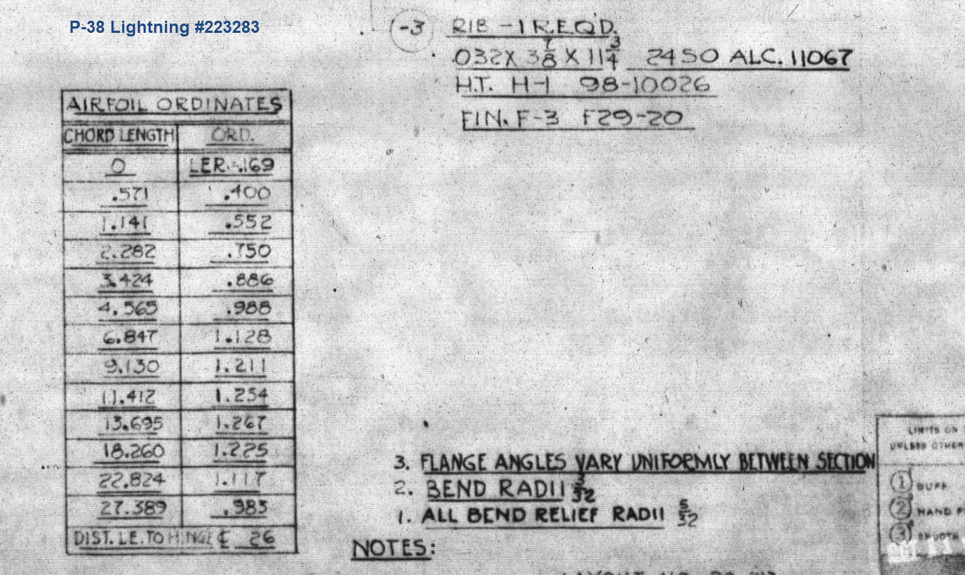
The Horizontal stabiliser ribs are based on the NACA 0010 airfoil profile which is listed as per the Lockheed drawings in the table on the left. The column on the immediate right is the calculated values to improve accuracy which also verifies the recorded data. The table on the right is the transposed calculated values for the main perpendicular Horizontal stabiliser rib with a chord length of 45″.
The above image is the plan view for the Stabiliser tip which shows the centres for the canted ribs and over to the right a number of red vertical dotted lines indicating the position of the reference perpendicular rib profiles. Between those ribs is a blue dotted line with a small circle indicator which is actually the main subject of this article.
The easiest way of defining the canted ribs is simply to loft the known perpendicular profiles and cut along the axis of the canted ribs…it definitely is the quickest way of doing this. However, that leaves a lot of miscellaneous activities in the cad model which just adds clutter.
Transposing the location of percentage increments from the rib table ordinate table to the canted ribs is done like this.
The perpendicular profile chord is the blue dotted line and the canted rib is the red centre line. The LENGTH is the chord length and the dimension A is the percentage increment on that line that we need to find the comparative intersection for on the cant rib. At this point, we do not know the LENGTH as this is dependent on the line position relative to the cant rib at whatever percentage increment we chose.
As mentioned at the start of this article for say a 20% chord dimension we could simply draw 5 lines in succession and apply an equal constraint and so on for the equal divisible portions…but that is not very practical.
So what we do is to locate the template rib line at any arbitrary point on the cant rib and then dimension the length…it does not matter at this stage what the dimension is. Now, this is the key thing we must do…select the LENGTH dimension and change it to a Driven Dimension. Now define the percentage increment (multiplied by Length) you wish to interrogate from the NACA table above and the template rib line will automatically relocate to a position where the Dim A is actually the percentage dimension you define of the total chord length. The software calculates the correct length according to the parameters specified.
An example would be where you specify 15%: you would write “0.15*D20” where D20 is the Driven Dimension.
I have included in the ordinate spreadsheets a table that will calculate the ordinate rib offsets depending on the chord length derived from the above exercise.
You then simply transfer those ordinate offsets to the intersection point of the cant rib. It really is quite clever when you think about it…you are asking the software to define the length of a line based on a percentage value relative to another canted line within boundaries specified by the arc.
Of course, I did not have to do this for all the cant rib offsets just the ones that were missing from the Lockheed drawings.
The P38 Lightning project is now finished. Only known dimensional data is included in this study. The engine Nacelle and Carb intake are omitted due to lack of dimensional information…however the creative among you will find it straightforward to interpolate fairly accurate profiles from the known information incorporated in this model and accompanying spreadsheet dataset.
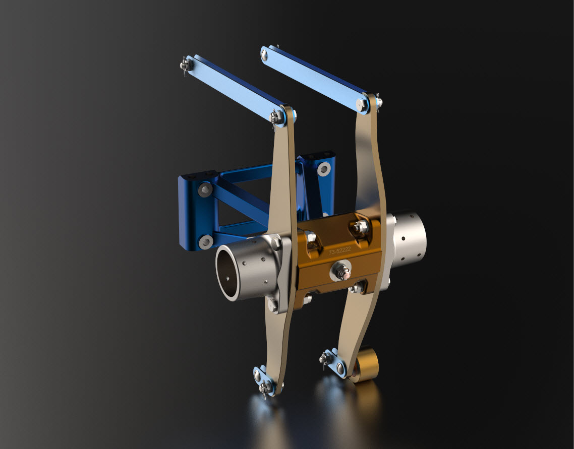
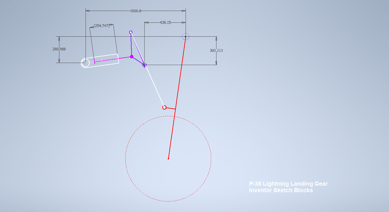
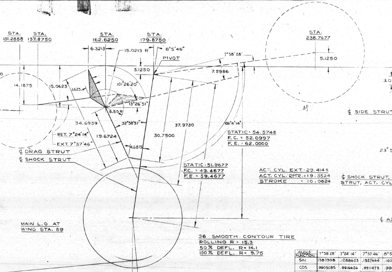
I have uploaded a video showing the mechanism for the Main Landing Gear for the Lockheed P-38 Lightning. This was created using the Inventor Sketch block feature which is a great tool to understand how these mechanisms work and provides an opportunity to examine the operational relationships.
Landing Gear mechanisms are quite complex and at first glance at the drawings, it can be difficult to fathom how they actually work. One way of visualising this mechanism and understanding the extent of the operation is to use Sketch Blocks.
The way this works is that you first build your sketch; minimise constraints, and select the elements that form each of the components; whether that be hydraulic cylinders, linkages, axles etc. Then you would constrain them according to how the mechanism should work…in this example, the cylinder actuator rod is constrained to align with the centre of the cylinder and virtually everything else is concentric constraints at each of the nodes. There are a number of good Youtube videos that show how this is done.
The dimension shown is a “driven” dimension which will change according to the location of the operation. You could of course have driven dimensions for the angles to check the max and minimum inclination. The quality of the video is not great but you get the idea.
For better precision, it is always best to use the Simulation environment with relative constraints applied accordingly to confirm operational parameters but for a quick check on movement, the Sketch Block feature is a good solution prior to committing to modelling.
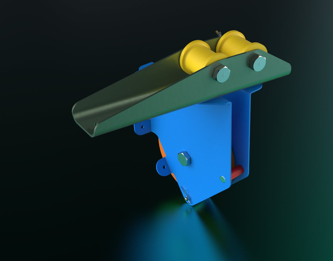
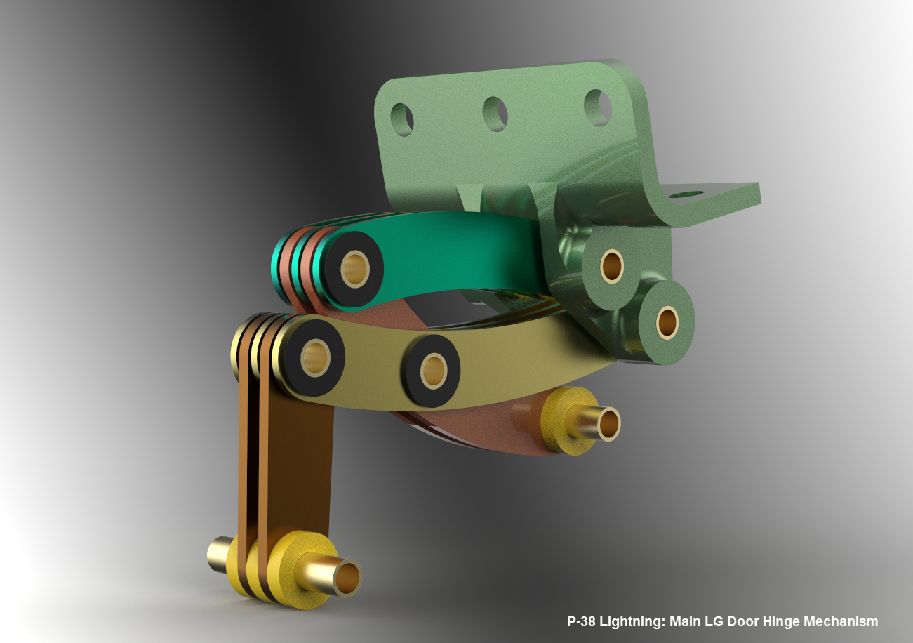
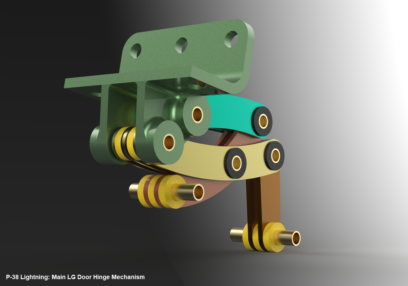
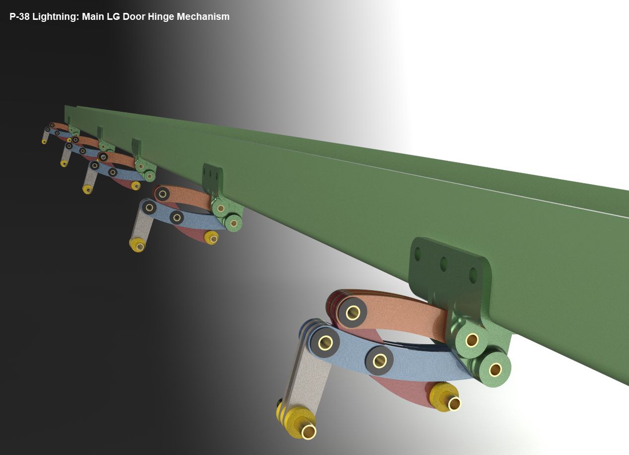
Update 16th June 2022 LG Hinges:
Have you ever wondered what the Main Landing Gear Door Hinges look like?…
These are the basic profiles for the P-38 Cockpit Canopy glass panels derived from the XP-38 drawings. Knowing that there were differences between the prototype XP-38 and the production models I was initially reluctant to accept the XP-38 dimensions for developing the cockpit canopy. The production drawings do not contain any useful information to develop these profiles nor indeed was there any drawing stating the inclination angle of the windshield. There was also not enough information from the Lockheed ordinate drawings for the fuselage frames which left me with the only option to use the XP-38 information.
It transpires the dimensions on the XP-38 drawings are indeed pertinent to the production models. There are exceptions which relate to the side windows.
The drawing on the left is the P-38H side glass frame and you can see this is dimensioned as a radius value which differs from the XP-38, which is defined by ordinate dimensions. There is also a slight variation in the overall length, so I naturally presumed that there may be other variables that conflicted with the prototype model. The only way to know for sure was to build the model based on the XP-38 and cross-check against known information with the production models.
So after 3 days of frustrating intensive work, I now have the base model for the XP-38 glass profiles and I have concluded that the profiles for the front, top and rear panels dimensionally are compatible with production variants. The only area that has marginally changed is the side panels, although changing from ordinate to radial dimensions still retains alignment with the known fuselage frames.
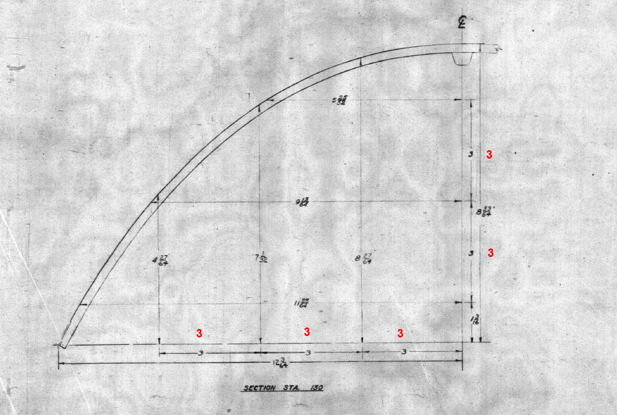
Also worth noting is that Lockheed uses a 3-inch grid system for aligning all the fuselage components which are useful when you are trying to locate these panels where no location is noted…you just have to align the 3-inch offsets to the grid. Each of the 3-inch offsets on this drawing section for example can be matched with the full-size grid to locate the correct elevation for the top glass panel and so on.
It is actually a really clever idea and helps obviate any doubt about where an item should be located.
One further tip when working with these Lockheed drawings is that for plan views and elevation views there may not be enough dimensions to fully locate a 3d point for determining a complex curved line.
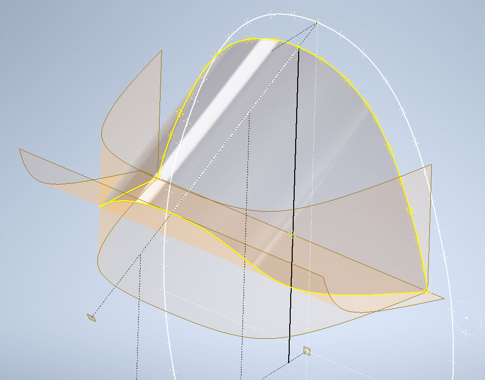
For the windshield, there was sufficient information in the vertical plane and the horizontal plane but as they were not related I could not derive specific 3d points from this data alone.
So I resolved to replicate this on 2 sketches and extrude a surface profile for each sketch. The intersection of the surfaces gave me the requisite 3d glass mold line.
The final check; that ensures this is correct; is to view the final glass panel along its axis to check that the curvature matches exactly with the top of the ordinate fuselage profile at STA 126…which it does.
For some reason, the ordinate dimensions are on STA 123 instead of STA 126 which means the end result will need to be projected to get the full glass panel model…I haven’t done that here. These are primarily dimensional studies and I tend to only include 3d models where this benefits the purpose of confirming data integrity. Oh by the way the inclination angle for the windshield is 27 degrees…don’t be sidetracked by the frame connectors that show 26.5 degrees…the reason for the 0.5-degree variance relates to the interface with the rubber sealing. Hopefully, you will find this useful.
When I started this project the Lockheed drawings seemed to be quite well organised with the provision of a number of what I thought were key ordinate drawings. These appeared to be full of tabulated dimensions and associated formulas. The wing layout and dimensional information were well documented so it was logical to assume this pattern would follow with the other drawings. Unfortunately, this was not to be the case with the Empennage drawings which required a lot more work thus this blog article.
Having worked my way through the vagaries of the wing design and the forward Boom section I then progressed to the Vertical Stabiliser Fin and Rudder drawings. The first drawing in the batch I looked at was an ordinate layout drawing which on closer inspection only provided the location of the spars and struts…there was no information on the Leading or Trailing edge curved profiles. So I ventured to look at Assembly drawing #223026 to see what information I could glean from that.
Again it was just the main component locations and little or no information on the curvature. However, there was the drawing for the Rudder Tab and yes indeed it did contain information on the curvature. At this point, I should note that the Lockheed drawings include some sketches which contain chord profile information for both the wings and empennage…unfortunately 80% of those are illegible.
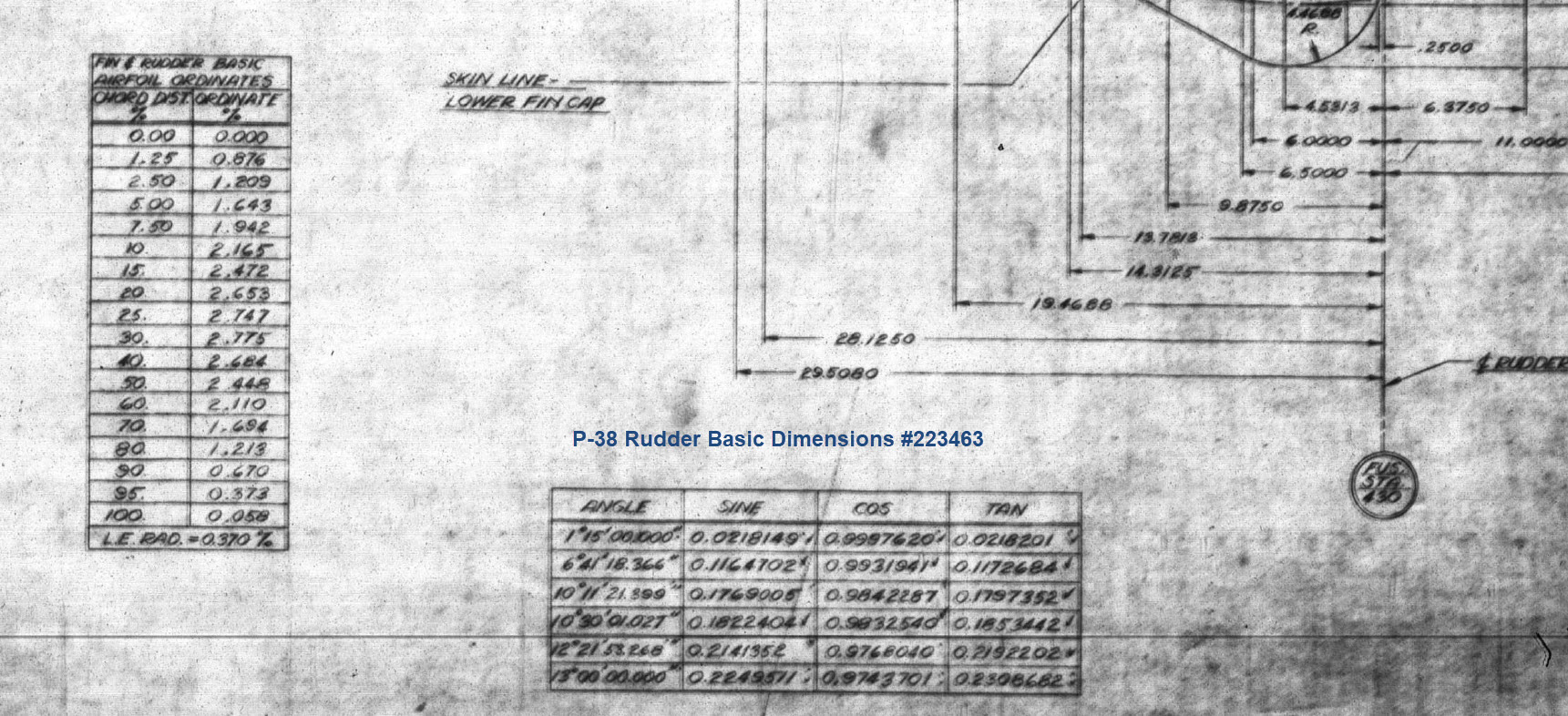
This sketch is the exception for the Fin/Rudder profiles at a specified WaterLine. This is where things got interesting because the chord dimension on this drawing did not match the dimension of the Rudder Tab at the same location after I had modelled it and furthermore did not match a comparative drawing in the Structural manual which also included dimensional information. It turns out that the Rudder and Tab Trailing edges are constructed in the same way as the main wing with an extended tab for jointing top and bottom sheet panels…which explains the dimensional variation.
The dimensions on the Basic layout sketch above and the corresponding information in the structural repair manual are actually relative to the rib chord and not to the finished edge.
As the above sketch was the only legible example of the requisite rib chord information I had to rethink my approach and reverse engineer the data on the Fin/Rudder’s ribs.
The Fin/Rudder rib drawings contain chord profiles for the ribs, though only partial I suspected that they may follow a standard format normally applied to rib airfoils i.e. percentage increments. It may seem an obvious comparison but in my experience, this is not always the case.
The drawing on the left is the partial profile information for the Fin/Rudder rib and the drawing on the right is the basic profile included on the Ordinate layout drawing I mentioned in the beginning. I surmised that if the Rib drawing follows the same convention as the Ordinate table with logical percentage increments it would be possible to determine the chord lengths of each rib.
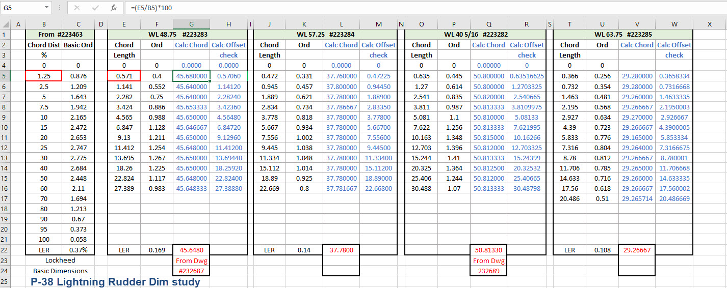
In excel I created this spreadsheet with the Ordinate Table on the left and subsequent tables containing information from the Fin/Rudder Rib drawings. The first 2 columns in each table are the values as noted on the drawings and then to check my theory that they followed a logical sequence I calculated the third column which indeed returned a close approximation of the actual chord length. The fourth column is the new offsets calculated from the derived chord length in each case.
Having established that the rib profile is as I expected it is now possible to create ordinate points to profile the Trailing Edge and define the contours for the Rudder’s ribs. Remember we also have a tab extension to which we have to add an additional fraction of an inch to get the final trimmed profile. As I am calculating and applying the new information to the CAD model sketches I maintain a 2d view to check the overall dimensions to see how they compare.
I am only halfway through the development of the Fin and Rudder layout as shown but will continue the same process to ascertain the remaining curve sections. At the end of the day and similarly the same with the wing the 2d drawing will display 2 lines profiling the Trailing Edge, one which will be the 100% chord ordinate and the other the extended tab. By the way please don’t use any of the dimensions noted on this drawing…it is a study with temporary dimensions!
A lot of work still to do on this which will have to be done for all the spars and ribs to ascertain the correct curvatures of the Trailing Edges. Where occasionally you need to derive specific information it is often beneficial to look at opportunities to interrogate what information you do have to determine the information you need.
Update 26th May 2022:
After extensive study and listing of ordinates in stacks of excel tables, I have managed to verify the Vertical Stabiliser dimensions. The Basic or True Rudder line noted on the sheet drawings is defined by the 100% chord dimension for the ribs…this is an important change to the wing trailing edge. Anyway as I need to take a break I thought it may be prudent to provide this update for your perusal. Still some work to do for the top and bottom profiles and of course a general tidy up would be in order…it is still a work in progress!
I could have just accepted the dimensions noted in the Structural repair manual as the end result would have been close. However, it is important where there are slight variations between the manual, the ordinate sketch and the part drawings that every effort is expended to understand the design intent and derive a correct solution.
One further point of interest: the profile for the Vertical Stabilizer is close to being symmetrical about the vertical centre of the full length of the rib chords. I marked out the centres of each rib profile and found only a 3.6mm difference for the top section, however, the variation in the lower section (below WL 21) is considerably more at 19mm… which is too much even accounting for the fractional accuracy from inch measurements.
Update 10th July 2022:
My study of the P-38 Lightning is now finished. I have documented all aspects of the aircraft and compiled an extensive record of dimensions in a comprehensive Excel spreadsheet. The 3d CAD model is supported with dimensioned 2d layout drawings with all models available in native IPT, IAM forms as well as Parasolid XT and 3d DWG.
For more information get in touch, as usual, contact me at hughtechnotes@gmail.com